Interim report released on 24th March 2017.
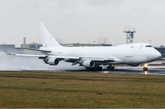
Photo TC-MCL, B747-412F, Manufactured on February 2003
INTERSTATE AVIATION COMMITTEE. AIR ACCIDENT INVESTIGATION COMMISSION
PRELIMINARY REPORT
Fatal accident
Boeing 747-412F, registration TC-MCL
Near Manas International Airport, Bishkek, Kyrgyz Republic
16.01.2017, 07:17 local time (01:17 UTC), nighttime
Factual Information
History of Flight
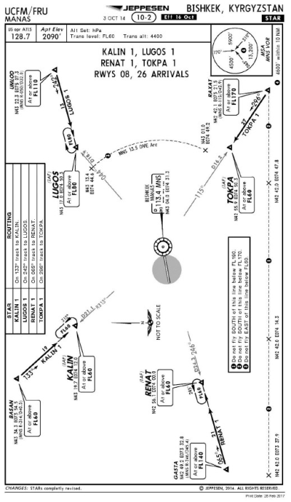
The intended flight route was from Chek Lap Kok Airport (VHHH, Hong Kong) via Manas International Airport (UCFM, Bishkek) to Ataturk Airport (LTBA, Istanbul)
The calculated aircraft Take Off Weight- TOW was about 342500 kg, with CG of 23% MAC. The a/c departed from Hong Kong at approximately 19:12 1 on 15.01.2017. At 19:37 the a/c reached FL 320. Further, starting at 20:43 FL 340 was maintained. The flight was conducted in autoflight mode.
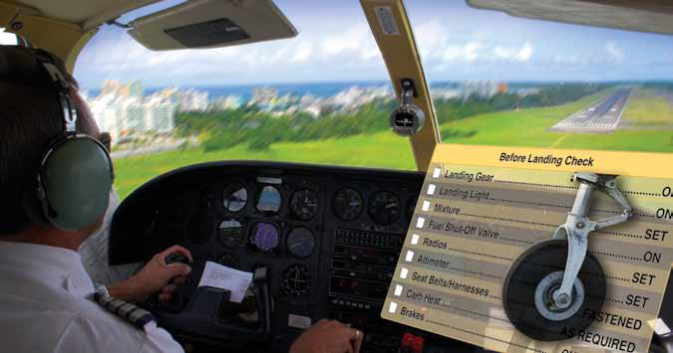
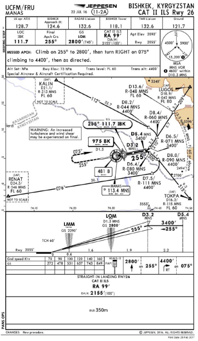
Before descending the crew conducted a low visibility approach and landing briefing. The ILS (111.7 MHz) and VOR/DME MNS (113.4 MHz) frequencies for RWY 26 approach were tuned.
At 00:41 on 16.01.2017 the aircraft – a/c entered Bishkek Area Control FIR. At 00:51 the crew reported they were ready for the descent. The controller cleared descent to FL 220. The descent from cruise flight level was initiated at approximately 00:52 at distance of 130 nm from VOR/DME MNS (Here in after unless otherwise stated reference is made to distances from VOR/DME MANAS that is installed 0.8 nm before RWY 26 end in direction open to landing course).
FL 220 was reached at approximately 00:59.
At 01:03:10 the crew requested further descent. The controller cleared descent to FL 180 to RAXAT reporting point.
At 01:05:55 the a/c reached FL 180. When overflying RAXAT the a/c was at that flight level.
At 01:06:02 the crew was handed over to Approach Control.
After the a/c overflew RAXAT the controller cleared further descent to FL 060 as per TOKPA 1 STAR.
Descent from FL 180 was initiated at 01:06:40 (a moment when the Auto Pilot – A/P FLIGHT LEVEL CHANGE mode was engaged). At its initial stage, the crew used FLIGHT LEVEL CHANGE A/P mode longitudinally, while laterally LATERAL NAVIGATION mode was used. During the descent, the crew also used V/S mode. Engines operational mode was close to flight idle. Within 01:09:18 to 01:14:32 (FL 123 to FL 044) the crew extended spoilers manually.
TOKPA reporting point over flight occurred at 01:11:18. The a/c was crossing FL 092 while in descent. According to the approach chart, FL 060 or above should be reached when overflying TOKPA.
At 01:11:55 the controller informed the crew on transition level (FL 060), QNH (1023 hPa) and cleared them for ILS approach to RWY 26.
At 01:12:00 the crew set QNH.
At 01:12:07 at a speed3 of 250 kt and distance of 12.5 nm the flap handle was set to 1º
At 01:12:42 the controller cleared the crew for the further descent to altitude 3400 ft. The a/c was meanwhile crossing FL 074 (Hereinafter unless otherwise stated QNH altitude is referred to)
The CVR record of cockpit communications shows that at that stage of flight the crew was monitoring the flight altitude and was aware they were higher than the STAR chart.
At 01:12:51 at a speed of 240 kt and distance of 9.8 nm the crew started extending flaps to 5º. A bit later the crew identified the ILS three-letter identifier (India Bravo Kilo) for RWY 26.
At 01:13:35 at a speed of 220 kt and distance of 7.2 nm the flap handle was set to 10º.
At 01:14:05 the Digital Flight Data Recorder – DFDR recorded LOC (Localizer) capture (Figure 1) and start of localizer establishing maneuver. At that time the a/c was at a distance of about 6 nm in descent at an altitude of 5655 ft (Height: 3600 ft)
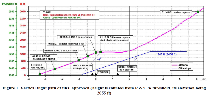 Figure from Interstate Aviation Committee Air Accident Investigation Commission Preliminary Report
Since 01:14:08 the three A/Ps were engaged. Autoflight was continued, LOC MODE engaged laterally and FLIGHT LEVEL CHANGE was active vertically. 3400 ft was selected as target altitude (glideslope capture altitude). As per the approach chart, this altitude shall be reached at a distance of 5.4 nm and maintained until 3.2 nm (glideslope capture).
At 01:14:26 at a speed of 190 kt and distance of 4.5 nm the flap handle was set to 20º.
A bit earlier, at 01:14:18 the crew initiated landing gear extension.
The final approach point for RWY 26 is at a distance of 3.2 nm. At this distance, the a/c was in descent, crossing 4000 ft.
At 01:15:03 at a speed of 190 kt and distance of 2.7 nm the flaps were set to 25º.
At 01:15:21 after the crew confirmed capturing the localizer, the a/c was handed over to Tower Control.
At 01:15:25 at a distance of 1.7 nm the a/c reached 3400 ft and ALT HOLD OPER A/P mode was engaged longitudinally.
Since that time the flight was performed at a constant altitude along the RWY 26 landing course. The a/c was significantly higher than the glideslope, the glideslope pointer was in full down position. The glideslope mode was armed (G/S MODE ARM), but the glideslope was not captured.
At 01:15:31 while the a/c was in level flight at 3400 ft LOM (Locator, Outer Marker) overflight was recorded (as per the approach chart LOM overflight altitude is 2800 ft). The CVR record contained no aural signal of LOM overflight. However, the LOM is indicated to both crew members on the PFD.
01:15:38 the controller informed the crew on the weather (wind calm, RVR: 400 m (threshold), 325 m (midpoint), 400 m (end), vertical visibility 160 ft) and cleared them for landing. RWY 26 is certified for ICAO CAT II operations.
At 01:15:50 at a speed of 175 kt and distance of 0.3 nm the flap handle was set to 30º.
A glideslope signal was captured at 01:15:52, at that time the a/c was almost over VOR/DME MANAS at a distance of approximately 1.1 nm from RWY 26 threshold, at an angle of approximately 9º (Figure 1). However, as per the approach chart, the rated glideslope angle is 3º (figure 4)
The a/c automatically initiated descent with a vertical speed of up to 1425 ft/min.
6 seconds after the glideslope capture LAND 3 autoland status annunciation was recorded. The crew called out the annunciation.
At 01:16:01 at 3300 ft LMM (Locator, Medium Marker)overflight was recorded (as per the approach chart LMM overflight altitude is 2290 ft). The CVR record contained no aural signal of LMM overflight. However, the LMM is indicated to both crew members on the PFD.
After the glideslope descent was initiated the glideslope pointer was fluctuating within – 4 to + 4 dots.
At 01:16:07, 15 seconds after the glideslope was captured, at 3150 ft AP CAUTION and FMA FAULT 2 events (See Section 1.18.1) were recorded. These events were continuously recorded almost until the end of the flight (until the FLARE A/P mode activation).
The descent was performed at approximately 160 kt CAS. The landing weight was about 274800 kg. MAP mode was selected on both pilots’ navigation displays with a scale range of 10 nm.
As the a/c was descending LAND 3 status degraded to LAND 2, which was confirmed by the crew callout.
Within 01:16:49 – 01:16:56 the EGPWS Mode 5 GLIDESLOPE alert was triggered 5 times (See Section 1.18.2). Further, the EGPWS system only provided information on reaching selected approach altitudes and minima.
At 01:17:04 the crew crossed RWY 26 departure end at a height of about 110 ft. At 01:17:05 EGPWS 100 ft radio altitude voice callout occurred while the decision height was 99 ft.
At 01:17:07 the FO called “Minimums”.
At 01:17:08 the PIC informed that there was no visual contact («NEGATIVE») and called to go-around.
At 01:17:09 A/P Flare mode was engaged and half a second later at 58 ft radar altitude TOGA switch was pushed as per the DFDR.
The Go-Around mode activation resulted in engine power increase, vertical acceleration of about 1.4 g and arresting descent. 3.5 seconds after the TOGA switch had been pushed the a/c hit slightly upsloping terrain and obstacles. The ground speed at the time of impact was 165 kt. The maximum recorded vertical acceleration was 6 g.
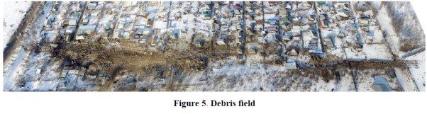
Initial impact occurred at a distance of approximately 930 m from RWY 26 departure end. The collision with terrain and obstacles resulted in hull loss, most of the a/c structure was consumed by the post-crash fire.
Injuries to Persons
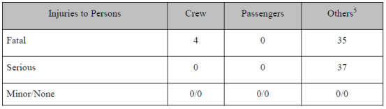
Others: Injured and killed persons on the ground. Table from Interstate Aviation Committee Air Accident Investigation Commission Preliminary Report
Damage to Aircraft
The a/c was totally destroyed and partly consumed by the post-impact fire.
Other Damage
According to the information provided by the Ministry of Internal Affairs of Kyrgyz Republic, 38 buildings in the settlement were broken, including 19 dwelling houses and 12 household outbuildings totally ruined and 7 dwelling houses partly broken.
Personnel Information
1. Flight Crew
Pilot-in-command
Date of birth: 10.11.1958
Total flight hours: 10808 h
Flight hours on B 747: 820 h
Flight hours on B 747 as PIC: 820 h
Flight hours over last month: 39 h 36 min
Flight hours over last 3 days: 06 h 04 min
Flight hours on accident day: 06 h 01 min
Total duty time on accident day: 09 h 10 min
First Officer
Date of birth: 01.01.1958
Total flight hours: 5894 h
Flight hours on B 747: 1758 h
Flight hours over last month: 32 h 33 min
Flight hours over last 3 days: 08 h 51 min
Flight hours on accident day: 06 h 01 min
Total duty time on accident day: 09 h 10 min
2. Air Traffic Control
Senior Controller (at Approach Control working station at the time of the accident)
Date of birth: 12.03.1980
Experience as air traffic controller: Since 2000
Authorizations: Ground Control, Tower Control, Approach Control, Upper Airspace Area Control
ATC Controller (at Tower Control working station at the time of the accident)
Date of birth: 06.07.1959
Experience as air traffic controller: Since Since 1992
Authorizations: Ground Control and Tower Control
Meteorological Information
At the time of the accident weather forecast for 00:00 on 16.01.2017 to 24:00 on 16.01.2017 was current for Manas Airport
TAF forecast for Manas Airport Issued on 15.01.2017, at 22:44, valid from 00:00 on 16.01.2017 to 24:00 on 16.01.2017:
Surface wind 240º – 4 mps, visibility 0200 freezing fog, vertical visibility 030 m, TEMPO from 00:00 on 16.01.2017 till 06:00 on 16.01.2017 wind 120 – 5 mps, visibility 0800 m, freezing fog smoke, vertical visibility 090 m, from 06:00 on 16.01.2017 surface wind 320 – 04 mps, visibility 1500 m, mist, clouds broken at 150 m, TEMPO from 06:00 on 16.01.2017 to 12:00 on 16.01.2017 visibility 0800 m, freezing fog, clouds few at 090 m.
Regular weather report for Manas Airport was broadcast via a VHF channel for 01:00 on 16.01.2017 in Russian and English:
Manas weather 01:00 surface wind calm, at 100 ft wind 110 degrees 01 mps, visibility 50 m RVR 300 m, freezing fog, vertical visibility 100 ft, temperature minus 09С, dewpoint minus 10ºС, QNH 1023 hPa, course 255, runway damp, braking action 0.6, NOSIG.
Actual weather at Manas Airport for runway course 255° at the time of the accident was as follows:
For 01:16: wind 60 degrees 01 mps, visibility: runway threshold 100/RVR 400 m, runway midpoint 100/RVR 350 m, runway end 100/RVR 400 m, vertical visibility 050 m, temperature minus 09°С, dewpoint minus 10°С, QNH 1023,9 hPa, RWY 26 damp, braking action 0.6, TREND NOSIG.
Aids to Navigation, Landing and ATC
Below is a list of ground navigation equipment supporting approach to landing for RWY 26:
– MSSR (Monopulse Secondary Surveillance Radar);
– ILS NM-7000 (111.7 MHz, IBK);
– VOR/DME (113.4 MHz, MNS);
– PAR-10C LMM (481 kHz);
– PAR-10C LOM (975 kHz).
The peculiarity of Manas International Airport is that ILS systems on both courses have the same frequency (111.7 MHz) while their letter identifiers are different. Based on the available information the system is configured in such a way that when the ILS for one course is engaged, the ILS for the other course is automatically disengaged.
Airdrome Information
Manas Airport is 23 km to the north of Bishkek. Manas Airdrome with RWY 08/26 equipped for precise ICAO CAT II approaches holds Certificate of Airdrome Conformity.
The airdrome has one runway, 4204 m long and 55 m wide. Airdrome designation – 4 E The runway has 4.5 m wide perimeter pavement along its entire length (concrete for 2.5 m, asphalt- concrete for 2 m) on each side of the runway.
Runway surface is 40 cm thick fibercrete.
Runway longitudinal slope is 0.0026 (0.26%). There are no longitudinal slope changes of more than 1.5%.
ARP elevation – 2080 ft (634 m). Threshold elevation: RWY 08 – 2090 ft (637 m); RWY 26 – 2055 ft (626 m).
The airstrip is 4324 m long and 300 m wide. The clearway measurements are as follows: RWY 08 – 400х300 m; RWY 26 – 250х300 m, surface type – ground.
There are ground runway end safety areas for RWYs 08/26 measured 240х110 m.
Manas Airdrome is limited by concrete and metal net fencing, along its entire perimeter.
Beyond the airdrome, at a distance of about 1000 m from the threshold of RWY 08 there are dwelling houses and outbuildings of Dacha-SU settlement, their height not exceeding the pertinent limitations.
Wreckage Information
The airframe was broken into multiple pieces, the largest of them being located within the last third of the wreckage path. The overview of the debris field is shown in
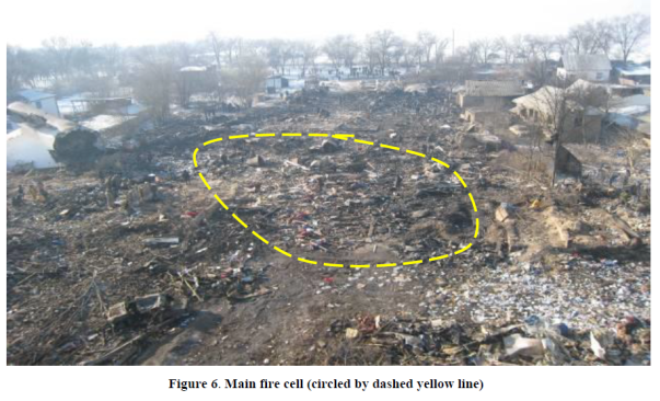
Photos from Interstate Aviation Committee Air Accident Investigation Commission Preliminary Report
There are no signs of fire or thermal impact on the pieces of fuselage, wing and engines located before the fire cell, either on the outside or on the inside. Beyond the debris field no airframe parts were found (fuselage, wing, empennage, etc.)
The vertical fin and horizontal stabilizers (Figure 7) remained attached to the tail part of the fuselage (pressure dome to the APU exhaust). Their final position was inverted. There were no signs of fire or soot on the fin.
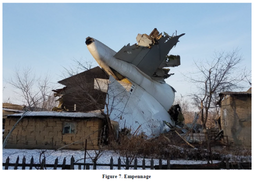
Photo from Interstate Aviation Committee Air Accident Investigation Commission Preliminary Report
The horizontal stabilizer’s center section, trim actuator and ball screw showed no external damage.
At the time of the accident, the wing flight control surfaces were consistent with the landing configuration. It was confirmed by the position of the leading and trailing edge flaps – all the way to the wing final stop.
Spoilers actuators with fragments of control surfaces were found, their position showing that at the time of the accident the spoilers were retracted (actuator drive cylinders pilled in).
The external examination of the cockpit revealed both pilots’ control columns bearing no external damage.
The elevators remained installed on the aircraft consistent with a pitch-up position. The mechanical coupling between the elevators and servo tabs was intact.
The Left-Hand aileron was torn. The Right-Hand aileron was broken into pieces. It was not possible to determine the aileron position at the time of the impact.
The pilots’ pedals had no external damage. The rudder consisting of two halves was not broken. It was not possible to determine the rudder position at the time of the impact.
There are no signs of liquid spillage or kinematics disconnect. The deformation and damage to the control cables, ducts and cords is consistent with the deformation and damage to the tail fuselage
Medical and Pathological Information
The investigation team is awaiting the results of the forensic examination of the persons killed in the accident.
Tests and Research
On 16.01.2017 the quality control laboratory of fuels and lubricants (Manas Airport) examined fuel samples drained from the LH wing (Sampling Act № 1-2 as of 16.01.2016). Based on its results it was concluded that the fuel met the pertinent specifications.
The Flight Control Computer recovered from the accident site has been sent to the NTSB in Washington DC, USA, for specific examinations.
An inspection flight of Manas ILS has been performed as per a specifically designed program coordinated with all participating States
Organizational and Management Information
Being analyzed.
Additional Information
1. FMA FAULT 2
As per the Boeing Company explanation, FMA FAULT 2 record means that the AFDS identified pitch mode failure that is the a/c could no longer be tracking the glideslope beam (see FCT 747 Pages 5.19 – 5.20).The mode failure results in the following:
– the pitch flight director bars are removed from the Primary Flight Displays –PFDs
– a yellow line is displayed through the G/S mode annunciation on the PFDs (FMA-Flight mode Annunciator);
– both MASTER CAUTION lights are illuminated;
– a MASTER CAUTION aural is activated;
– an amber AUTOPILOT caution message is annunciated on EICAS –Engine Indication and Cree Alerting System.
Meanwhile, the A/P will not disengage. In the pitch channel, the A/P will maintain an inertial path which tracks a 3º glideslope regardless of the actual glideslope angle at a certain airdrome. The path will be maintained until a valid glideslope signal is regained or until the crew intervenes by disengaging the A/P or initiating a go-around (TOGA switch pushed).Without crew intervention, the A/P will maintain the inertial path until the FLARE mode is engaged. The Autoland status LAND 3 (or LAND 2) will also continue being annunciated. According to the manufacturer’s information, the inertial path generation is a feature in Boeing airplane models 737, 747-400/-8, 757, 767, 777, 787 that allows the A/P to continue the approach for disruptions of either G/S or LOC ground station signals.
2. “GLIDESLOPE” alert (EGPWS Mode 5)
According to the EGPWS Manufacturer’s Pilot Guide, below 1000 ft radio altitude, a deviation of 1.3 dots below the glideslope will trigger a ‘soft’ alert with a caution light and an aural GLIDESLOPE alert at 20% of full volume. Once below 300 ft radio altitude, a deviation of 2.0 dots below the glideslope beam will trigger a ‘hard’ alert with the aural alert sounding repeatedly at full volume
Safety Recommendations
- It is recommended that the crews pay attention to following approach charts, monitoring distance and altitude during reference points (FAF, LOM, LMM) overflight when conducting ILS approaches, especially ICAO CAT II and CAT III approaches.
- . It is recommended that flight crews be informed that in case ground references are not visible, go-around shall be initiated not lower than the established decision height.
- . It is recommended that air traffic controllers, in case they have pertinent equipment available, inform flight crews on significant altitude deviations from that established by the approach charts, especially for ICAO CAT II and CAT III approaches and Low Visibility Procedures, therefore, introducing respective amendments to the procedures and job description of air traffic control personnel should be considered.
- It is recommended that top management of airlines operating Boeing aircraft (all models) arrange theoretical and practical (if needed) training to cover awareness, procedures and aspects of flight operations when A/P switches to inertial mode during glideslope descent. Consider the applicability of this recommendation to aircraft of other manufacturers.
- It is recommended that the FAA in cooperation with the Boeing Company consider the practicability of changing the A/P logic to prevent occurrences of following inertial glideslope descent (in LAND 3 or LAND 2 mode) in cases when approach path does not allow landing in the appropriate area on the runway. It is recommended that other certification authorities and aircraft manufacturers consider the applicability of this recommendation taking into account actual A/P algorithms
- It is recommended that airport administrations analyze the acceptability of constructions in the immediate vicinity of airdromes and, in case findings are raised, take appropriate decisions in cooperation with pertinent authorities.
Excerpted from Межгосударственный авиационный комитет (МАК) – Interstate Aviation Committee Air Accident Investigation Commission (IAC), Interim Report
**********************
 By Laura Victoria Duque Arrubla, a medical doctor with postgraduate studies in Aviation Medicine, Human Factors and Aviation Safety. In the aviation field since 1988, Human Factors instructor since 1994. Follow me on facebook Living Safely with Human Error and twitter@SafelyWith. Human Factors information almost every day
_______________________