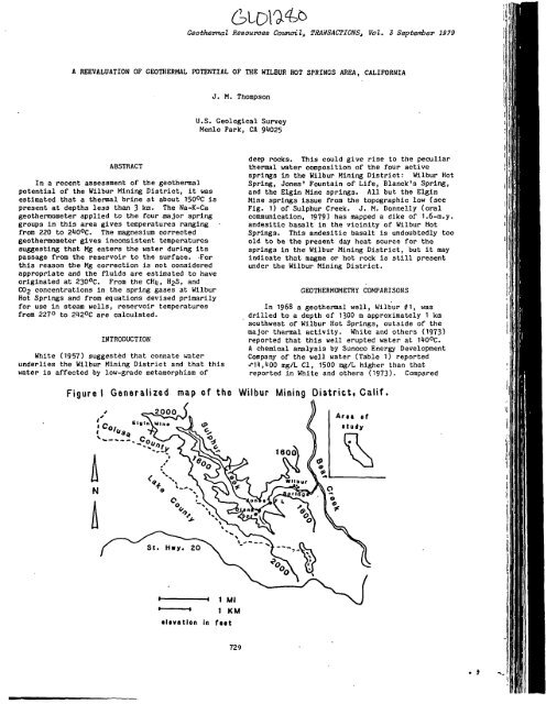
Figure I Generalized map of the Wilbur Mining ... - University of Utah
Figure I Generalized map of the Wilbur Mining ... - University of Utah
Figure I Generalized map of the Wilbur Mining ... - University of Utah

You also want an ePaper? Increase the reach of your titles
YUMPU automatically turns print PDFs into web optimized ePapers that Google loves.
Geol^ertnal Resources Council, TRANSACTIONS, Vol. 3 Septetrber 1979<br />
A REEVALUATION OF GEOTHERMAL POTENTIAL OF THE WILBUR HOT SPRINGS AREA, CALIFORNIA<br />
ABSTRACT<br />
In a recent assessment <strong>of</strong> <strong>the</strong> geo<strong>the</strong>rmal<br />
potential <strong>of</strong> <strong>the</strong> <strong>Wilbur</strong> <strong>Mining</strong> District, it was<br />
estimated that a <strong>the</strong>nnal brine at about 150°C is<br />
present at depths less than 3 km. The Na-fC-Ca<br />
geo<strong>the</strong>rmometer applied to <strong>the</strong> four major spring<br />
groups in this area gives temperatures ranging<br />
from 220 to 2lOOC. The magnesium corrected<br />
geo<strong>the</strong>rmometer gives inconsistent temperatures<br />
suggesting that Mg enters <strong>the</strong> water during its<br />
passage from <strong>the</strong> reservoir to <strong>the</strong> surface. 'For<br />
this reason <strong>the</strong> Mg correction is not considered<br />
appropriate and <strong>the</strong> fluids are estimated to have<br />
originated at 230°C. From <strong>the</strong> CHij, HjS, and<br />
CO2 concentrations in <strong>the</strong> spring gases at <strong>Wilbur</strong><br />
Hot Springs and from equations devised primarily<br />
for use in steam wells, reservoir temperatures<br />
from 227° to 242°C are calculated.<br />
INTRODUCTION<br />
White (1957) suggested that connate water<br />
underlies <strong>the</strong> <strong>Wilbur</strong> <strong>Mining</strong> District and that this<br />
water Is affected by low-grade metamorphism <strong>of</strong><br />
J. M. Thompson<br />
U.S. Geological Survey<br />
Menlo Park, CA 91025<br />
deep rocks. This could give rise to <strong>the</strong> peculiar<br />
<strong>the</strong>rmal water composition <strong>of</strong> <strong>the</strong> four active<br />
springs in <strong>the</strong> <strong>Wilbur</strong> <strong>Mining</strong> District: <strong>Wilbur</strong> Hot<br />
Spring, Jones' Fountain <strong>of</strong> Life, Blanck's Spring,<br />
and <strong>the</strong> Elgin Mine springs. All but <strong>the</strong> Elgin<br />
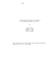
Mine springs issue from <strong>the</strong> topographic low (see<br />
Fig. 1) <strong>of</strong> Sulphur Creek. J. M. Donnelly (oral<br />
communication, 1979) has <strong>map</strong>ped a dike <strong>of</strong> 1.6-m.y.<br />
andesitic basalt in <strong>the</strong> vicinity <strong>of</strong> <strong>Wilbur</strong> Hot<br />
Springs. This andesitic basalt is undoubtedly too<br />
old to be <strong>the</strong> present day heat source for <strong>the</strong><br />
springs in <strong>the</strong> <strong>Wilbur</strong> <strong>Mining</strong> District, but it may<br />
indicate that magma or hot rock is still present<br />
under <strong>the</strong> <strong>Wilbur</strong> <strong>Mining</strong> District.<br />
GE0THERMC»1ETRY COMPARISONS<br />
In 1968 a geo<strong>the</strong>nnal well, <strong>Wilbur</strong> SI, was<br />
drilled to a depth <strong>of</strong> 1300 m approximately 1 km<br />
southwest <strong>of</strong> <strong>Wilbur</strong> Hot Springs, outside <strong>of</strong> <strong>the</strong><br />
major <strong>the</strong>rmal activity. White and o<strong>the</strong>rs (1973)<br />
reported that this well erupted water at IIOOC.<br />
A chemical analysis by Sunoco Energy Development<br />
Company <strong>of</strong> <strong>the</strong> well water (Table 1) reported<br />
^11,loo mg/L Cl, 1500 mg/L higher than that<br />
reported in White and o<strong>the</strong>rs (1973). Compared<br />
<strong>Figure</strong> I <strong>Generalized</strong> <strong>map</strong> <strong>of</strong> <strong>the</strong> <strong>Wilbur</strong> <strong>Mining</strong> District, Calif.<br />
• Iivatlon In fttt<br />
729<br />
ill
Thompson<br />
T OC<br />
pH<br />
SIO2<br />
Al<br />
Fe<br />
Mn<br />
Ca<br />
Mg<br />
Sr<br />
Ba<br />
Na<br />
K<br />
Ll<br />
NHi|<br />
HCO 3<br />
CO3<br />
so^<br />
Cl<br />
F<br />
Br<br />
I<br />
B<br />
H2S<br />
Na-K-•Ca<br />
Mg corr<br />
SIO2<br />
Na-K-Ca<br />
Adlabatic<br />
Conductive<br />
^Analyses,in mg/L<br />
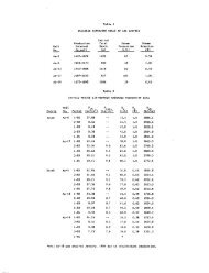
Table 1. Averaged concentrations for spring and well water<br />
in <strong>the</strong> <strong>Wilbur</strong> mining district'<br />
<strong>Wilbur</strong><br />
Hot Spring<br />
52<br />
7.5<br />
176<br />
1.8<br />
0.17<br />
O.Of<br />
2.5<br />
15<br />
3.6<br />
3.1<br />
8700<br />
^08<br />
11.6<br />
29'*<br />
6900<br />
—<br />
356(H)<br />
9980<br />
2.1<br />
19<br />
12<br />
233<br />
165<br />
236<br />
8it<br />
218<br />
_—_<br />
Jones'<br />
Fountain <strong>of</strong><br />
Life<br />
60<br />
7.7<br />
89<br />
0.35<br />
0.05<br />
2.6<br />
31<br />
1.6<br />
3.0<br />
9880<br />
it 32<br />
10.7<br />
120<br />
57IO<br />
—<br />
71<br />
11,700<br />
3.5<br />
31<br />
23<br />
2H0<br />
232<br />
118<br />
223<br />
to <strong>Wilbur</strong> Hot Springs (see Table 1) <strong>Wilbur</strong> ffl<br />
geo<strong>the</strong>nnal well contains (1) a higher chloride<br />
content (11,100 vs. 10,000 mg/L), (2) a lower<br />
sulfate content (260 vs. 36O mg/L) and (3) a much<br />
lower magnesium content (2 vs. 15 mg/L).<br />
The magnesium corrected Na-K-Ca geo<strong>the</strong>rmometer<br />
(Fournier and Potter, 1978) indicates temperatures<br />
ranging from 10 to 160°C. However, because <strong>the</strong><br />
country rock around <strong>Wilbur</strong> Hot Springs is<br />
principally serpentinite, <strong>the</strong> high magnesium in<br />
<strong>Wilbur</strong> Hot Spring is probably due to serpentine<br />
dissolution. The uncorrected Na-K-Ca (Fournier<br />
and Truesdell, 1973) temperatures, which range<br />
from 220 to 218°C, may be more reasonable.<br />
Water from <strong>Wilbur</strong> ff 1 geo<strong>the</strong>rmal well has a<br />
Na-K-Ca temperature <strong>of</strong> 2IIOC (Table 1) and very<br />
little magnesium; a correction <strong>of</strong> only 1°C is<br />
calculated.<br />
Due to possible silica addition from<br />
serpentine dissolution, severe difficulties are<br />
encountered when using dissolved silica<br />
Blanck's<br />
Spring<br />
12<br />
7.8<br />
121<br />
0.19<br />
0.05<br />
3.5<br />
69<br />
1.1<br />
1.5<br />
7220<br />
360<br />
6.9<br />
125<br />
6390<br />
—<br />
180<br />
8050<br />
2.3<br />
21<br />
18<br />
150<br />
730<br />
232<br />
16<br />
198<br />
——<br />
Elgin Mine<br />
Springs<br />
61<br />
198<br />
0.17<br />
1.0<br />
1.8<br />
28<br />
3.7<br />
9330<br />
510<br />
11<br />
213<br />
7270<br />
—<br />
86<br />
11,550<br />
3.2<br />
30<br />
25<br />
210<br />
170<br />
211<br />
118<br />
208<br />
— •'—<br />
<strong>Wilbur</strong> fi<br />
Geo<strong>the</strong>rmal<br />
well<br />
110<br />
8.8<br />
133<br />
— 1<br />
2<br />
10,000<br />
110<br />
—<br />
275<br />
5170<br />
1170<br />
263<br />
11,100<br />
16<br />
—<br />
• —<br />
118<br />
211<br />
213<br />
201<br />
Meteoric<br />
water<br />
19.5<br />
6.8<br />
21<br />
— 3.1<br />
182<br />
—<br />
—<br />
132<br />
1.1<br />
0.16<br />
—<br />
1020<br />
0<br />
185<br />
83<br />
.37<br />
—<br />
—<br />
conoencration in estimating <strong>the</strong>rmal reservoir<br />
temperatures. The difficulties include <strong>the</strong><br />
following: (1) <strong>the</strong> silica may have already<br />
polymerized or precipitated so that direct<br />
application <strong>of</strong> <strong>the</strong> silica geo<strong>the</strong>rmometer (Fournier<br />
and Rowe, 1966) will indicate a low reservoir<br />
temperature; (2) <strong>the</strong> <strong>the</strong>rmal water is probably<br />
mixed with dilute meteoric water giving rise to<br />
<strong>the</strong> observed spring water compositions and<br />
temperatures; and (3) <strong>the</strong>.diluting water or <strong>the</strong><br />
warm mixed water may contain some silica<br />
originating from low-temperature serpentine<br />
dissolution. For comparison, <strong>the</strong> conductive and<br />
adiabatic (with assumed subsurface steam loss at<br />
lOQOC) silica-mixing-model temperatures<br />
(Truesdell and Fournier, 1977) <strong>of</strong> <strong>the</strong> warm springs<br />
are shown in Table 1. Despite all <strong>of</strong> <strong>the</strong> possible<br />
problems using silica concentrations in springs<br />
from this area, <strong>the</strong> adiabatic mixed-water<br />
temperatures are in moderate to good agreement<br />
with <strong>the</strong> Na-K-Ca temperatures. Fournier (1979)'<br />
indicated that silica reequilibratlon is more<br />
likely to occur than Na-K-Ca reequilibratlon. The<br />
—
silica concentration in a water sample from <strong>Wilbur</strong><br />
ffl geo<strong>the</strong>rmal well is below that expected in a<br />
220° to 210OC water; however, It may be in<br />
approximate equilibrium with quartz at 150°C or<br />
chalcedony at 13OOC (Truesdell, 1976). The<br />
quartz equilibrium temperatures at 150OC and <strong>the</strong><br />
Na-K-Ca equilibrium temperatures at 230°C in<br />
<strong>Wilbur</strong> ffl are inferred to represent high initial<br />
water tanperature (230°C) and slow rate <strong>of</strong> water<br />
movement. Ultimately, little confidence can be<br />
placed in <strong>the</strong> temperatures estimated from <strong>the</strong><br />
dissolved silica concentrations <strong>of</strong> <strong>the</strong> springs<br />
because <strong>of</strong> <strong>the</strong> numerous possible complications.<br />
In an attempt to calculate a third independent<br />
reservoir temperature, gas samples were collected<br />
and analyzed. Franco D'Amore and A. H. Truesdell<br />
(written communication, 1979) have devised a<br />
system <strong>of</strong> equations for geo<strong>the</strong>rmal steam wells<br />
which quantitatively relate <strong>the</strong> concentrations <strong>of</strong><br />
CHi) and CO2 and <strong>of</strong> H2S and CO2 measured at<br />
<strong>the</strong> surface to <strong>the</strong> temperature in <strong>the</strong> producing<br />
zone. Using <strong>the</strong>ir equations <strong>the</strong> reservoir<br />
temperatures in Table 2 were calculated for <strong>Wilbur</strong><br />
Hot Springs. These temperatures are in excellent<br />
agreement with <strong>the</strong> uncorrected Na-K-Ca<br />
tanperatures from <strong>the</strong> spring waters.<br />
Table 2.—Gas Analyses <strong>of</strong> <strong>Wilbur</strong> Hot Springs ^<br />
Date 12-11- -77<br />
Collect or AHT<br />
CO2<br />
H2S<br />
NH3<br />
H2<br />
Ar<br />
02<br />
N2<br />
CHi)<br />
C2H6<br />
TOTAL<br />
T<br />
51.2<br />
2.66<br />
0.622<br />
9.36X<br />
0.319<br />
U.71<br />
29.0<br />
2.36<br />
0.00<br />
93.87<br />
2120C<br />
Wilb ur Hot Springs<br />
0-"<br />
12-11-77<br />
AHT<br />
69-3<br />
2.91<br />
0.00<br />
2.66x10"<br />
0.217<br />
1.26<br />
18.8<br />
3.33<br />
0.00<br />
95.85<br />
237°C<br />
8-15-78<br />
JMT<br />
76.7<br />
2.92<br />
, 0.0323<br />
•^ 1.08x10<br />
0.188<br />
0.635<br />
15.1<br />
3.28<br />
0.00<br />
98.22<br />
227 °c<br />
^Analyses in mole percent. Analyses by Nancy L.<br />
Nehring, U.S. Geological Survey.<br />
The <strong>Wilbur</strong> Hot Springs water composition may<br />
result if one part diluting water such as that in<br />
Table 1 mixes with two or three parts <strong>of</strong> <strong>the</strong>nnal<br />
water such as that from <strong>the</strong> <strong>Wilbur</strong> ffl geo<strong>the</strong>rmal<br />
well. This diluting water may be unusual because<br />
it contains a high magnesium content from<br />
dissolved serpentine. Alternatively, <strong>the</strong><br />
magnesium from serpentine dissolution may not<br />
enter <strong>the</strong> system until after mixing. Ano<strong>the</strong>r<br />
possible scheme is that 230°C water mixes with<br />
connate water similar to that described by White<br />
and o<strong>the</strong>rs (1973) to form <strong>the</strong> J'ISOOC water in<br />
731<br />
Thompson<br />
<strong>Wilbur</strong> ffl geo<strong>the</strong>rmal well. This water <strong>the</strong>n mixes<br />
with cold meteoric water in different proportions<br />
producing <strong>the</strong> various spring water compositions.<br />
This model Is not favored because it requires<br />
three different water types. Presently, <strong>the</strong> time<br />
at which <strong>the</strong> magnesium enters <strong>the</strong> system cannot be<br />
determined. The additional sulfate (115 mg/L)<br />
probably arises from oxidation <strong>of</strong> H2S in <strong>the</strong><br />
near surface region.<br />
CONCLUSIONS<br />
The brine in <strong>the</strong> <strong>Wilbur</strong> ffl geo<strong>the</strong>rmal well<br />
result from <strong>the</strong> mixing <strong>of</strong> deep <strong>the</strong>nnal water <strong>of</strong><br />
unknown composition at a temperature near 230^0<br />
and connate water such as that described by White<br />
and o<strong>the</strong>rs (1973). Alternatively, <strong>the</strong> connate<br />
water may have been heated to near 230°C and<br />
<strong>the</strong>n mixed with meteoric water in proportions <strong>of</strong><br />
2:1 or 3:1. This diluting meteoric water may<br />
contain as much as I80 mg/L Mg. This mixed v/ater<br />
may <strong>the</strong>n slowly rise to <strong>the</strong> surface without<br />
appreciable residence in a large reservoir where<br />
Na-K-Ca reequilibratlon could occur. The depth to<br />
<strong>the</strong> 230°C water is unknown.<br />
REFERENCES<br />
journier, R. 0., 1979, Geochemical and hydrologic<br />
considerations and <strong>the</strong> use <strong>of</strong><br />
enthalpy-chloride diagrams in <strong>the</strong> prediction<br />
<strong>of</strong> underground conditions in hot-spring<br />
systems: Journal <strong>of</strong> Volcanology and<br />
Geo<strong>the</strong>rmal Research, v. 5, - 1-I6.<br />
Fournier, R. 0., and Potter, R. W., II, 1978, A<br />
magnesium correction for <strong>the</strong> Na-K-Ca chemical<br />
geo<strong>the</strong>rmometer: U.S. Geological Survey<br />
Open-File Report 78-986, 2i| p.<br />
Fournier, R. 0., and Rowe, J. J., 1966,<br />
Estimation <strong>of</strong> underground temperatures from<br />
<strong>the</strong> silica content <strong>of</strong> water from hot springs<br />
and wet-steam wells: American Journal Science<br />
261,- p. 685-697. •<br />
Fournier, R. 0., and Truesdell, A. H., 1973, An<br />
empirical Na-K-Ca geo<strong>the</strong>rmometer for natural<br />
water: Geochlmica et Cosmochimica Acta, 37,<br />
p. 1255-1275.<br />
Truesdell, 1976, Summary <strong>of</strong> Section III<br />
Geochemical and Geophysical Techniques in<br />
Exploration: Proceedings 2nd U. N. Symposium<br />
on <strong>the</strong> Development and use <strong>of</strong> Geo<strong>the</strong>rmal<br />
Resources, San Francisco, 19875, v. 1 p<br />
Ixxiii.<br />
Truesdell, A. H., and Fournier, R. 0., 1977,<br />
Procedure for estimating <strong>the</strong> temperature <strong>of</strong><br />
hot-water component in a mexlco water by using<br />
a plot <strong>of</strong> dissolved silica versus enthalpy:<br />
Journal Reaearch U.S. Geological Survey, v. 5,<br />
p. 19-52.<br />
White, D. E., 1957, Magmatic, connate, and<br />
metamorphic waters: Geological Society <strong>of</strong><br />
America Bulletin, v. 68(12) pt. 1, p.<br />
1659-1682.<br />
White, D. E., Barnes, Ivan, and O'Neil, J. R.,<br />
1973, Thermal and mineral waters <strong>of</strong> nonmeteoric<br />
origin, California Coast Ranges:<br />
Geological Society <strong>of</strong> America Bulletin v. 81,<br />
p. 517-560.
Geo<strong>the</strong>rmal Resources Council, TRAHSACTIOUS, Vol. 3 Septetiiber 1979<br />
BOREHOLE TEMPERATURE STUDIES OF<br />
THE LAS ALTURAS GEOTHERMAL ANOMALY, NEW MEXICO<br />
Paul Morgan, Chandler A. Swanberg<br />
and Richard L. Lohse<br />
New Mexico State <strong>University</strong><br />
Box 3D, Las Cruces, NM 88003<br />
ABSTRACT INTRODUCTION<br />
Three phases <strong>of</strong> borehole temperature studies<br />
have been made relative to <strong>the</strong> Las Alturas geo<strong>the</strong>rmal<br />
anomaly in sou<strong>the</strong>rn New Mexico: i) logging<br />
<strong>of</strong> "free" holes; ii) shallow gradient study; and<br />
ill) analysis <strong>of</strong> data from two 300m tests. A maximum<br />
temperature <strong>of</strong> 62.5''C (145°F) has been measured<br />
at 300m in one <strong>of</strong> <strong>the</strong> tests, and <strong>the</strong> data<br />
indicate that <strong>the</strong> source <strong>of</strong> <strong>the</strong> anomaly Is a hydro<strong>the</strong>rmal<br />
circulation system. A simple analysis<br />
<strong>of</strong> <strong>the</strong> temperature data indicate vertical water<br />
flow rates <strong>of</strong> <strong>the</strong> order <strong>of</strong> 1x10"^ m/s ('»' 1 ft/yr).<br />
The borehole temperature data have provided valuable<br />
information for delineating, evaluating and<br />
characterizing <strong>the</strong> nature <strong>of</strong> <strong>the</strong> source <strong>of</strong> <strong>the</strong><br />
jnomaly.<br />
NMSU SUBSURFACE TEMPERATURE<br />
RESEARCH STUDY<br />
Geophysical, engineering and economic studies<br />
all indicate that <strong>the</strong> Las Alturas geo<strong>the</strong>rmal anomaly,<br />
located adjacent to <strong>the</strong> city <strong>of</strong> Las Cruces,<br />
New Mexico (<strong>Figure</strong> 1), is a potentially economic<br />
low temperature geo<strong>the</strong>rmai resource for direct<br />
heat applications at <strong>the</strong> New Mexico State <strong>University</strong><br />
campus (Gunaji et^ al.-, 1978; Dicey et al. ,<br />
this volume). Borehole temperature studies have<br />
been made in and around <strong>the</strong> Las Alturas anomaly in<br />
three phases: i) regional exploration comprising<br />
temperature measurements in "free" holes, 11) drilling<br />
and measurement <strong>of</strong> 30m temperature gradient<br />
» , .V I • -r--? ..'I-<br />
Flg. 1 Index <strong>map</strong> <strong>of</strong> that part <strong>of</strong> Las Cruces, New Mexico, which includes <strong>the</strong> New Mexico State <strong>University</strong><br />
campus (to <strong>the</strong> west) and <strong>the</strong> Las Alturas area (Wells, labeled 6-9). Also shown are <strong>the</strong> locations<br />
<strong>of</strong> <strong>the</strong> boreholes used for temperature studies.<br />
469
Morgan, et at.<br />
holes over <strong>the</strong> anomaly prior to <strong>the</strong> siting <strong>of</strong><br />
deeper test wells; and lii) drilling and measurement<br />
<strong>of</strong> two 300m test wells. This summary presents<br />
<strong>the</strong> results <strong>of</strong> <strong>the</strong> three phases <strong>of</strong> <strong>the</strong><br />
temperature study and <strong>the</strong> interpretation <strong>of</strong> <strong>the</strong><br />
subsurface temperature data<br />
REGIONAL BOREHOLE TEMPERATURE STUDIES<br />
There are numerous boreholes in <strong>the</strong> Las<br />
Cruces area, drilled primarily for domestic water<br />
supply to depths <strong>of</strong> a few hundred meters. Eight<br />
abandoned water wells were available for temperature<br />
measurements in <strong>the</strong> Immediate vicinity <strong>of</strong><br />
Las Alturas; <strong>the</strong> locations for six <strong>of</strong> <strong>the</strong>se<br />
(NMSU-1,-2,-3, LAOl, 02, 03) are shown on <strong>Figure</strong> 1.<br />
The remaining two wells in <strong>the</strong> area are located<br />
<strong>of</strong>f <strong>the</strong> <strong>map</strong>, <strong>the</strong> J. ABRAMS well being approximately<br />
two miles to <strong>the</strong> NNW, and DA-1 approximately<br />
six miles to <strong>the</strong> east. The temperature data<br />
from <strong>the</strong>se eight wells are shown tn <strong>Figure</strong> 2.<br />
1401- I<br />
I<br />
t<br />
LAS ALTU,=!AS AND<br />
SURROUNOING AREAS<br />
TEMPERATURE-DEPTH<br />
PLOTS<br />
::.TZ^ Tt5',.S t.'.'C<br />
iORI20KT,iL ~:-'it<br />
Fig. 2 Temperature data from "free" boreholes in<br />
<strong>the</strong> vicinity <strong>of</strong> Las Alturas.<br />
The temperature logs fall Into three distinct<br />
categories: negative gradients, normal gradients,<br />
and high gradients. Three wells with negative<br />
gradients, NMSU-1, NMSU-2, and J. ABRAMS, are all<br />
located to <strong>the</strong> west <strong>of</strong> Interstate-25, which approximately<br />
divides <strong>the</strong> Irrigated areas <strong>of</strong> <strong>the</strong> Rio<br />
Grande Valley to <strong>the</strong> west from <strong>the</strong> undeveloped<br />
areas <strong>of</strong> <strong>the</strong> mesa to <strong>the</strong> east. The data from<br />
<strong>the</strong>se wells clearly indicate recharge <strong>of</strong> groundwater<br />
by downward water flow. Three wells east <strong>of</strong><br />
1-25—NMSU-3, LAOl, and DA-1—show reasonably uniform<br />
positive temperature gradients <strong>of</strong> <strong>the</strong> order<br />
<strong>of</strong> 40°C/km (2.2°F/100 ft) below a depth <strong>of</strong> 20 m.<br />
These gradients are typical <strong>of</strong> <strong>the</strong> gradients<br />
470<br />
normally measured in sediments in <strong>the</strong> Rio Grande<br />
Rift. Two wells at Las Alturas, LA02 and LA03,<br />
have dramatically higher gradients, <strong>of</strong> about<br />
SOCC/km (16.5°F/100 ft), down to <strong>the</strong> water table<br />
at approximately 60m, below which depth <strong>the</strong> gradients<br />
systematically decrease. These two wells<br />
provided <strong>the</strong> first temperature measurements in<br />
<strong>the</strong> geo<strong>the</strong>rmal anomaly and yielded gradients below<br />
<strong>the</strong> water table which indicate that <strong>the</strong> anomaly<br />
Is caused by a hydro<strong>the</strong>nnal circulation system.<br />
In addition, <strong>the</strong>se two wells provided valuable<br />
information for fur<strong>the</strong>r temperature studies:<br />
<strong>the</strong> high gradients above <strong>the</strong> water table are<br />
essentially established in LA02 and LA03 at a<br />
depth <strong>of</strong> 10 to 20m, which indicates that 30m is<br />
an adequate depth for additional temperature<br />
gradient boreholes.<br />
SHALLOW GRADIENT BOREHOLES<br />
A program <strong>of</strong> shallow temperature gradient<br />
boreholes was planned to confirm <strong>the</strong> extension <strong>of</strong><br />
<strong>the</strong> Las Alturas geo<strong>the</strong>rmal anomaly beneath <strong>University</strong><br />
land adjacent to Las Alturas, and to provide<br />
additional data for site selection for deeper<br />
tests. On <strong>the</strong> basis <strong>of</strong> <strong>the</strong> temperature results<br />
from LA02 and LA03, 30m was chosen as <strong>the</strong> depth<br />
for <strong>the</strong> shallow gradient holes.<br />
Two holes, NMSU-4 and NMSU-5, were initially<br />
drilled to <strong>the</strong> east <strong>of</strong> Las Alturas at <strong>the</strong> locations<br />
shown on <strong>Figure</strong> 1. The temperature data<br />
from <strong>the</strong>se holes, shown in <strong>Figure</strong> 3, indicate<br />
that <strong>the</strong> anomaly increases to <strong>the</strong> east <strong>of</strong> Las<br />
Alturas. The measured gradients in NMSU-4 and -5<br />
are 416 and 387°C/km (22.8 and 21.2°F/100 ft),<br />
respectively. The anomaly is <strong>the</strong>reby confirmed<br />
to extend to <strong>the</strong> east beneath <strong>University</strong>-owned<br />
land.<br />
Data from an earlier electrical resistivity<br />
study at Las Alturas (Smith, 1977; Jiracek and<br />
Gerety, 1978) suggest that <strong>the</strong> anomaly extends at<br />
least one mile to <strong>the</strong> north <strong>of</strong> NMSU-4. Based on<br />
<strong>the</strong> resistivity interpretation, <strong>the</strong> IA02 and LA03<br />
borehole temperature data, and local geologic<br />
inforraation, it is thought that <strong>the</strong> most likely<br />
origin for <strong>the</strong> anomaly is a hydro<strong>the</strong>rmal circulation<br />
system controlled by a KW-J tending fault.<br />
A pr<strong>of</strong>ile <strong>of</strong> four boreholes, NMSU-6, -7, -8, and<br />
-9, were <strong>the</strong>refore drilled on an ENE line to <strong>the</strong><br />
north <strong>of</strong> <strong>the</strong> proven temperature anomaly to provide<br />
data for deeper test site selection. The locations<br />
<strong>of</strong> <strong>the</strong> holes are shown in <strong>Figure</strong> 1. Temperature<br />
data from <strong>the</strong>se holes (<strong>Figure</strong> 3) clearly<br />
define <strong>the</strong> westem margin <strong>of</strong> <strong>the</strong> anomaly with<br />
gradients increasing to <strong>the</strong> east as follows:<br />
NMSU-6, 88°C/km (4.8''F/100 ft); NMSU-7, 320°C/km<br />
(17.6''F/100 ft); NMSU-8, 446°C/km (24.5°F/100 ft).<br />
The anomaly appears to peak before <strong>the</strong> eastern<br />
hole on <strong>the</strong> pr<strong>of</strong>ile, where a gradient <strong>of</strong> 433°C/km<br />
(23.8''F/100 ft) was measured, although this is not<br />
absolutely defined. Unfortunately, institutional<br />
barriers at this stage prevented <strong>the</strong> drilling <strong>of</strong><br />
an additional gradient hole to <strong>the</strong> east. A tentative<br />
interpretation <strong>of</strong> all <strong>the</strong> temperature data<br />
Is that hot water rises along a NNW striking fault<br />
to a zone crossing between <strong>the</strong> two wells NMSU-8<br />
and -9, and <strong>the</strong>n diffuses laterally.<br />
r<br />
s
J<br />
0<br />
10<br />
X<br />
a.<br />
^20<br />
30<br />
2") 22<br />
/<br />
,/<br />
\<br />
\<br />
\<br />
38°C/km-J<br />
300m TEST WELLS<br />
\ \<br />
\(J1<br />
24<br />
K<br />
Two 300m test wells were drilled on <strong>University</strong><br />
land adjacent to Las Alturas under <strong>the</strong> supervision<br />
<strong>of</strong> L. Chaturvedi <strong>of</strong> <strong>the</strong> Civil Engineering<br />
Department at NMSU. The wells were sited on <strong>the</strong><br />
basis <strong>of</strong> <strong>the</strong> interpretation <strong>of</strong> <strong>the</strong> data from <strong>the</strong><br />
shallow gradient hole pr<strong>of</strong>ile, at <strong>the</strong> locations<br />
shown in <strong>Figure</strong> 1, based on <strong>the</strong> following logic.<br />
The first test well, DTI, was sited 100m east<br />
(downdip on <strong>the</strong> assumed fault) <strong>of</strong> <strong>the</strong> apparent<br />
peak <strong>of</strong> <strong>the</strong> anomaly defined by <strong>the</strong> temperature<br />
gradient pr<strong>of</strong>ile. With this well it was hoped to<br />
intersect and stay in <strong>the</strong> anomaly source to total<br />
depth. The second well, DT2, was drilled 0.4<br />
miles west <strong>of</strong> DTI along <strong>the</strong> pr<strong>of</strong>ile, between<br />
shallow wells HMSU-7 and -8. This site was selected<br />
so that if <strong>the</strong> interpretation <strong>of</strong> <strong>the</strong> source<br />
<strong>of</strong> <strong>the</strong> anomaly as a narrow fault-controlled zone<br />
<strong>of</strong> rising hot water were incorrect, this well<br />
would intersect a more laterally extensive source<br />
at a greater depth from DTI, but at a closer<br />
distance to <strong>the</strong> potential user, <strong>the</strong> NMSU campus.<br />
If <strong>the</strong> narrow fault source interpretation were<br />
correct, however, DT2 would provide information<br />
about <strong>the</strong> lateral flow from <strong>the</strong> system, and act as<br />
a site for a reinjection well, if required. Wells<br />
DTI and DT2 were drilled in December 1978 and<br />
January 1979 and completed as temperature test<br />
wells at depths <strong>of</strong> 300 and 360m respectively with<br />
two-inch water filled casing.<br />
Temperature data from <strong>the</strong> two 300m test wells<br />
are shown in <strong>Figure</strong> 4. The first well, DTI,<br />
TEMP CO<br />
26 28 30 32 34 36<br />
NMSU SH/lLLOW GEOTHERMAL TEST<br />
BOREHOLE TEMPERATURE LOGS<br />
\ , \ ^ ^ 0 \ ^ LOGS WITHIN 72HRS OF DRILLING<br />
\ V ^ ^ ^<br />
\^x<br />
\ " N V ^ V \ /-446°C/km<br />
320°C/krn—1 TT L-4 33 .c/km<br />
Morgan, et al.<br />
point <strong>the</strong> gradient becomes negative, indicating a<br />
heating <strong>of</strong> <strong>the</strong> zone around 160m by a lateral flow<br />
<strong>of</strong> hot water. Below 275m <strong>the</strong> gradient in DT2 becomes<br />
positive again, with <strong>the</strong> temperature increasing<br />
to 49.6''C (121°F) at 360m, <strong>the</strong> base <strong>of</strong><br />
<strong>the</strong> well. These data clearly Indicate <strong>the</strong> source<br />
<strong>of</strong> <strong>the</strong> anomaly to be in <strong>the</strong> vicinity <strong>of</strong> DTI, with<br />
a lateral hydro<strong>the</strong>rmal flow towards DT2 to <strong>the</strong><br />
west. The nature <strong>of</strong> <strong>the</strong> circulation to <strong>the</strong> east<br />
<strong>of</strong> DTI has not yet been determined.<br />
The curvature in <strong>the</strong> geo<strong>the</strong>rmal gradient in<br />
DTI can be used to estimate <strong>the</strong> vertical component<br />
<strong>of</strong> water flow in strata penetrated by <strong>the</strong><br />
well using <strong>the</strong> relationship<br />
q = K -7- + pCvdT,<br />
dz<br />
(1)<br />
where q Is <strong>the</strong> total vertical component <strong>of</strong> heat<br />
flow, K is <strong>the</strong> <strong>the</strong>rmal conductivity <strong>of</strong> a zone,<br />
dT/dz is <strong>the</strong> temperature gradient in <strong>the</strong> zone, p<br />
and C are <strong>the</strong> density and specific heat <strong>of</strong> water<br />
respectively, v Is <strong>the</strong> vertical component <strong>of</strong><br />
water flow velocity, and dT is <strong>the</strong> temperature<br />
drop across <strong>the</strong> zone. By using temperature gradients<br />
and temperature drops across adjacent zones,<br />
and assuming q to remain constant, <strong>the</strong> velocity<br />
V can be calculated. Using this technique, vertical<br />
water flows <strong>of</strong> between 0.3 and 1.4x10"' m/s<br />
(0.3 and 1.4 ft/yr) have been calculated for <strong>the</strong><br />
DTI temperature data. These calculations assumed<br />
a density <strong>of</strong> 1 gm/cm^ for <strong>the</strong> effective water<br />
density in equation (1). For absolute water flow<br />
velocities <strong>the</strong> numbers given above should be<br />
divided by <strong>the</strong> fractional porosity <strong>of</strong> <strong>the</strong> strata<br />
(.12 to .30, L. Chaturvedi, unpublished report).<br />
Unlike <strong>the</strong> measured gradients in DT2 and <strong>the</strong><br />
six shallow gradient holes, <strong>the</strong> gradient in DTI<br />
shows some curvature above <strong>the</strong> water table. This<br />
curvature prevents a direct comparison <strong>of</strong> <strong>the</strong><br />
shallow gradient in DTI with <strong>the</strong> gradients In<br />
NMSU-8 and -9, although its temperature at 30m<br />
<strong>of</strong> 34.45°C (94.0°F) is higher than <strong>the</strong> temperatures<br />
in <strong>the</strong> two flanking holes at <strong>the</strong> same depth,<br />
34.25°C (93.6''F) and 33.79°C (92.8°F) for NMSU-8<br />
and -9, respectively. DTI <strong>the</strong>refore appears to<br />
be close to <strong>the</strong> peak <strong>of</strong> <strong>the</strong> anomaly, and <strong>the</strong><br />
curvature In <strong>the</strong> gradient above <strong>the</strong> water table<br />
may be due to a significant non-vertical component<br />
<strong>of</strong> heat flow close to <strong>the</strong> shallow source <strong>of</strong> <strong>the</strong><br />
anomaly.<br />
CONCLUSIONS AND FUTURE STUDIES<br />
Borehole temperatures <strong>of</strong> <strong>the</strong> Las Alturas<br />
geo<strong>the</strong>rmal anomaly have partially defined <strong>the</strong><br />
lateral extent <strong>of</strong> <strong>the</strong> anomaly, provided information<br />
for <strong>the</strong> siting <strong>of</strong> deeper tests, and confirmed <strong>the</strong><br />
source <strong>of</strong> <strong>the</strong> anomaly to be a hydro<strong>the</strong>rmal circulation<br />
system. Modelling <strong>of</strong> electrical resls-<br />
• tivity data shows a 5 ohm-m low resistivity zone<br />
around <strong>the</strong> peak <strong>of</strong> <strong>the</strong> anomaly delineated by <strong>the</strong><br />
shallow temperature gradient data (Sraith, 1977,<br />
Jiracek and Gerety, 1978), but <strong>the</strong> borehole temperature<br />
data have provided <strong>the</strong> most diagnostic<br />
472<br />
information for delineating and interpreting <strong>the</strong><br />
nature <strong>of</strong> <strong>the</strong> geo<strong>the</strong>rmal anomaly.<br />
During <strong>the</strong> next few months it is planned to<br />
drill a deeper test well, up to 750m deep, into<br />
<strong>the</strong> geo<strong>the</strong>rmal system (L. Chaturvedi, personal<br />
communication). Fur<strong>the</strong>r shallow gradient holes<br />
are planned over <strong>the</strong> center <strong>of</strong> <strong>the</strong> anomaly to<br />
provide information for <strong>the</strong> siting <strong>of</strong> this well.<br />
An extension <strong>of</strong> <strong>the</strong> heat flow analysis outlined<br />
above indicates a fur<strong>the</strong>r decrease in <strong>the</strong> gradient<br />
below 300m, with <strong>the</strong> temperature possibly<br />
increasing to as little as 1 to 4''C (2 to 7*F)<br />
at 750m, giving a bottom hole temperature in <strong>the</strong><br />
range <strong>of</strong> 64 to 67''C (147 to 153°F). This analysis<br />
assumes that <strong>the</strong> vertical water flow rates<br />
estimated for <strong>the</strong> zone from 300m up to <strong>the</strong> water<br />
table are representative <strong>of</strong> <strong>the</strong> flow rates below<br />
300m. If this analysis is correct, <strong>the</strong> source <strong>of</strong><br />
<strong>the</strong> hot water for <strong>the</strong> hydro<strong>the</strong>rmal system could<br />
be groundwater circulation down to a depth <strong>of</strong> a<br />
little over 1 km, with a geo<strong>the</strong>rmal gradient<br />
typical for <strong>the</strong> area (40°C/km, 2.2°F/100 ft).<br />
This extrapolation <strong>of</strong> <strong>the</strong> data uses many as yet<br />
unproven assumptions, however, which only <strong>the</strong><br />
drilling <strong>of</strong> <strong>the</strong> third deep well can test.<br />
ACKNOOT.EDGEMENTS<br />
Funds for drilling <strong>the</strong> six shallow gradient<br />
holes were arranged by H. A. Daw <strong>of</strong> <strong>the</strong> New<br />
Mexico Energy Institute at NMSU-<br />
REFERENCES<br />
Gunaji, N. N., Chaturvedi, L., Thode, E.,<br />
LaFrance, L., Swanberg, C. A., and Walvakar,<br />
A., 1978, A geo<strong>the</strong>rmal field near New Mexico<br />
State <strong>University</strong> and its potential as a<br />
campus energy supplier, Geo<strong>the</strong>rmal Resources<br />
Council, Transactions, v. 2, p. 241-244.<br />
Jiracek, G. R., and Gerety, M. T., 1978, Comparison<br />
<strong>of</strong> surface and downhole resistivity<br />
<strong>map</strong>ping <strong>of</strong> geo<strong>the</strong>rmal reservoirs in New<br />
Mexico, Geo<strong>the</strong>rmal Resources Council,<br />
Transactions, v. 2, p. 335-336.<br />
Smith, C., 1977, On <strong>the</strong> electrical evaluation <strong>of</strong><br />
three sou<strong>the</strong>rn New Mexico geo<strong>the</strong>rmal areas,<br />
unpublished M.S. <strong>the</strong>sis. <strong>University</strong> <strong>of</strong> New<br />
Mexico, Albuquerque, New Mexico, 110 p.<br />
*<br />
m<br />
• «
Geo<strong>the</strong>nnal Resources Council, TRANSACTIONS, Vol. 3 Septetrher 1979<br />
CONTINUOUS GRAVITY OBSERVATIONS AT THE GEYSERS:. A PRELIMINARY REPORT<br />
ABSTRACT<br />
A cryogenic gravimeter has been installed at<br />
The Geysers to continuously monitor gravity variations<br />
at <strong>the</strong> Mgal level. A 38-day record is presented<br />
to illustrate <strong>the</strong> type <strong>of</strong> information that<br />
can be obtained from such an instrument. In<br />
addition to information directly related to mass<br />
transport within <strong>the</strong> reservoir, <strong>the</strong> data reveal a<br />
sudden 6 ygal decrease in gravity prior to a local<br />
earthquake. We also observe a 5 ugal increase in<br />
gravity during a heavy rainfall; however, interpretation<br />
<strong>of</strong> gravity variations at this level is<br />
limited by uncertainty in tilting <strong>of</strong> <strong>the</strong> gravimeter<br />
pier. The potential Irapact <strong>of</strong> continuous<br />
gravity observations on <strong>the</strong> study <strong>of</strong> reservoir<br />
characteristics is discussed.<br />
THE CRYOGENIC GRAVIMETER<br />
Jeffrey J. Olson and Richard J. Warburton<br />
<strong>University</strong> <strong>of</strong> California at San Diego<br />
La Jolla CA 92093<br />
Although cryogenic gravimeters have been in<br />
existence for several years (Goodkind and Pro<strong>the</strong>ro^<br />
1968, and Warburton and Goodkind, 1978), this is<br />
<strong>the</strong> first use <strong>of</strong> such an instrument in a geo<strong>the</strong>rmal<br />
application. The instrument differs from conventional<br />
gravimeters in that mechanical springs<br />
and levers are replaced by magnetic fields generated<br />
from persistent currents in colls <strong>of</strong> superconducting<br />
wire. These fields support a one-inch •<br />
dlamecer superconducting sphere (<strong>the</strong> graviroeter's<br />
only moving part) with a force that does not<br />
significantly diminish in time, due to <strong>the</strong> persistence<br />
<strong>of</strong> superconducting currents. Thus <strong>the</strong><br />
cryogenic gravimeter does not exhibit <strong>the</strong> instrumentally<br />
produced signal drift which is characteristic<br />
<strong>of</strong> conventional gravimeters. Several years<br />
<strong>of</strong> gravity observations at Pinon Flat in sou<strong>the</strong>rn<br />
California indicate that <strong>the</strong> total Instrumental<br />
drift is 0 ± 5 ygal/yr. A planned side-by-side<br />
test <strong>of</strong> two cryogenic gravimeters at Pinon Flat<br />
should determine whe<strong>the</strong>r this residual variation<br />
is <strong>of</strong> instrumental or geophysical origin.<br />
The short term precision <strong>of</strong> <strong>the</strong> cryogenic<br />
gravimeter appears to be limited only by <strong>the</strong> uncertainty<br />
with which <strong>the</strong> contributions frora known<br />
sources such as earth and ocean tides and atmospheric<br />
density variations can be subtracted. The<br />
data presented below indicate that this can be<br />
accomplished empirically to a precision <strong>of</strong> ±1<br />
ligal. Spurious tilting <strong>of</strong> <strong>the</strong> gravimeter platform<br />
can degrade this performance, but tilt will soon<br />
be controlled by <strong>the</strong> addition <strong>of</strong> an automatic<br />
519<br />
leveling system.<br />
OBSERVATIONS AT THE GEYSERS<br />
A cryogenic gravimeter was installed in<br />
February <strong>of</strong> 1979 in The Geysers steam field at<br />
latitude 38° 48' 25" and longitude 122° 48' 50".<br />
This site is on a spur <strong>of</strong> ridge which extends<br />
downward from Well Sulphur Bank 19 toward Units 3<br />
and 4. McLaughlin (1974) <strong>map</strong>s this general area<br />
as a quaternary landslide, however, <strong>the</strong> spur<br />
appears to be an outcrop <strong>of</strong> relatively unfractured<br />
Franciscan graywacke. Wea<strong>the</strong>red graywacke<br />
slightly uphill <strong>of</strong> <strong>the</strong> outcrop was excavated to a<br />
depth <strong>of</strong> 2 - 3 m to expose bedrock, upon which a<br />
3 m high reinforced concrete pier was erected.<br />
The gravimeter platform rests on this pier, supported<br />
on three points two <strong>of</strong> which are heavy<br />
duty micrometer heads to allow alignraent <strong>of</strong> <strong>the</strong><br />
gravimeter with <strong>the</strong> vertical. The active element<br />
<strong>of</strong> <strong>the</strong> gravimeter is immersed in liquid helium in<br />
a Dewar which is fixed to <strong>the</strong> platform.<br />
The output signal from <strong>the</strong> gravimeter is in<br />
<strong>the</strong> form <strong>of</strong> an analog voltage which is filtered<br />
electronically for sampling at a variety <strong>of</strong> rates<br />
from 20 seconds to 15 minutes. Barometric<br />
pressure as measured by a temperature regulated<br />
aneroid barometer is also filtered and monitored<br />
at 15 minute intervals. These signals are recorded<br />
in <strong>the</strong> field on digital tape cassettes by a<br />
microcomputer-controlled data system, which can<br />
also transmit stored data by telephone to our laboratory<br />
for inspection.<br />
A sample <strong>of</strong> raw data toge<strong>the</strong>r with <strong>the</strong> results<br />
<strong>of</strong> various stages <strong>of</strong> its reductiori are shown<br />
in <strong>Figure</strong> 1. All four graphs are plotted as<br />
functions <strong>of</strong> time at 15 minute Intervals beginning<br />
at 067:00:00:00 UTC and ending 38 days later at<br />
105:00:00:00 UTC. The observed gravity signal,<br />
<strong>Figure</strong> la, is dominated by smooth tidal variations<br />
(<strong>the</strong> coarseness <strong>of</strong> this graph is an artifact <strong>of</strong><br />
<strong>the</strong> digital plotter: <strong>the</strong> point density is nearly<br />
1000 points per inch on this scale). The principal<br />
component <strong>of</strong> this signal is <strong>the</strong> direct gravitational<br />
attraction <strong>of</strong> <strong>the</strong> moon and sun toge<strong>the</strong>r<br />
with <strong>the</strong> effects <strong>of</strong> deformation <strong>of</strong> <strong>the</strong> earth's surface<br />
due to tidal forces and loading from ocean<br />
tides. These tidal effects contain little information<br />
relevant to <strong>the</strong> geo<strong>the</strong>rmal reservoir and<br />
must be removed before local effects can be observed.<br />
This can be accomplished by subtraction
Olson, et al<br />
<strong>of</strong> a <strong>the</strong>oretically generated tide signal, to<br />
account for <strong>the</strong> direct attraction effects, followed<br />
by least squares removal <strong>of</strong> <strong>the</strong> strongest remaining<br />
tidal spectral components, to account for<br />
ocean loading effects.<br />
The resulting detided gravity signal is shown<br />
in <strong>Figure</strong> lb; <strong>the</strong> upward direction on <strong>the</strong> plot<br />
corresponds to increasing strength <strong>of</strong> gravity. .<br />
The detided gravity signal contains variations <strong>of</strong><br />
up to 13 ligal over a few days; however, most <strong>of</strong><br />
this is due to large scale atmospheric density<br />
fluctuations associated with <strong>the</strong> motion <strong>of</strong> wea<strong>the</strong>r<br />
systems, as is evident from comparison with <strong>the</strong><br />
barometric pressure record. <strong>Figure</strong> Ic. The upward<br />
direction on this plot corresponds to decreasing<br />
pressure, thus <strong>the</strong> central peak in <strong>Figure</strong> Ic in-f<br />
dlcates a strong low pressure system. Superimposed<br />
on <strong>the</strong>se major variations are minor oscillations<br />
due to <strong>the</strong> global semidiurnal atmospheric<br />
tides and local pressure fluctuations. As demonstrated<br />
by Warburton and Goodkind (1977), gravity<br />
effects due to major barometric pressure fluctuations<br />
can be removed from <strong>the</strong> detided gravity signal<br />
by least squares subtraction <strong>of</strong> <strong>the</strong> barometric<br />
pressure signal. The fitting coefficient yields<br />
an empirical barometric pressure admittance, which<br />
in this case amounts to 0.27 ygal/mbar. In o<strong>the</strong>r<br />
words, as much as 9 ligal <strong>of</strong> <strong>the</strong> detided gravity<br />
variations in <strong>Figure</strong> lb were due to atmospheric<br />
effects.<br />
Removing <strong>the</strong>se atmospheric effects produces<br />
<strong>the</strong> residual gravity signal shown in <strong>Figure</strong> Id.<br />
As in <strong>the</strong> o<strong>the</strong>r plots, a decreasing signal implies<br />
decreasing strength <strong>of</strong> gravity as occurs during<br />
mass extraction or surface uplift. Several features<br />
which were previously obscured by atmospheric<br />
effects are now apparent. Most remarkable<br />
<strong>of</strong> <strong>the</strong>se is <strong>the</strong> sudden drop <strong>of</strong> nearly 6 vigal which<br />
occured on day 078. Closer scrutiny on an expanded<br />
scale reveals that <strong>the</strong> drop was not instantaneous:<br />
<strong>the</strong> gravity decrease was linear in time over<br />
a two and one-half hour period. Moreover, a separate<br />
high frequency output channel from <strong>the</strong><br />
gravimeter indicated no unusual seismic activity<br />
or disturbance <strong>of</strong> <strong>the</strong> Instrument during this<br />
period; <strong>the</strong> decrease was quiet and gentle. However,<br />
two hours after this gravity change had<br />
ceased, <strong>the</strong> high frequency channel shows a local<br />
earthquake, which, according to Bufe (unpub. data)<br />
was <strong>of</strong> magnitude 3. The sign and magnitude <strong>of</strong><br />
this gravity event are consistent with an uplift<br />
<strong>of</strong> <strong>the</strong> gravimeter by approximately 2 cm.<br />
The second noteworthy event in <strong>the</strong> residual<br />
•VW^'V''^\Ayv.,^^-V ^"^^^^<br />
^ • ^ ' ' ^ ^ ' ' ^ ' ' ' ^ ^ ^ ^ ' ^ ^<br />
070 075 080 085 090 095 100 105<br />
(a) observed<br />
gravity<br />
(b) detided<br />
(c) barometric<br />
pressure<br />
(d) residual<br />
gravity<br />
<strong>Figure</strong> 1. A 38-day data segment from The Geysers, illustrating <strong>the</strong> extraction <strong>of</strong> a<br />
barometrically adjusted residual gravity signal from <strong>the</strong> raw gravity and<br />
barometric pressure signals.<br />
520
gravity signal is a rapid but Irregular 5 pgal increase<br />
beginning on day 086. This increase in<br />
gravity occurs over an 18 hour period which coincides<br />
precisely with <strong>the</strong> duration <strong>of</strong> <strong>the</strong> only significant<br />
rainfall In this 38 day data segment.<br />
Analysis <strong>of</strong> rainfall effects in barometrically<br />
adjusted gravity residuals is simplified by <strong>the</strong><br />
fact that <strong>the</strong>re is a slight decrease in barometric<br />
pressure directly associated with <strong>the</strong> release <strong>of</strong><br />
mass from <strong>the</strong> atmosphere. This decrease in<br />
pressure equals <strong>the</strong> weight per unit area <strong>of</strong> <strong>the</strong><br />
released mass. If we let Ag represent <strong>the</strong> gravitational<br />
attraction <strong>of</strong> a sheet <strong>of</strong> water <strong>of</strong> thickness<br />
equal to <strong>the</strong> depth <strong>of</strong> rainfall, <strong>the</strong>n it can<br />
be shown that <strong>the</strong> barometric pressure correction<br />
used to produce <strong>Figure</strong> Id contributes an amount<br />
-Ag to <strong>the</strong> residual gravity signal starting at <strong>the</strong><br />
time <strong>of</strong> <strong>the</strong> rainfall. Thus <strong>the</strong> net result <strong>of</strong> rainfall<br />
on barometrically adjusted gravity is simply<br />
to produce an apparent change by an amount -Ag if<br />
<strong>the</strong> sheet <strong>of</strong> water comes to rest above <strong>the</strong> gravimeter,<br />
or +Ag if <strong>the</strong> sheet lies below <strong>the</strong> gravimeter.<br />
In both cases, <strong>the</strong>se changes vanish as<br />
<strong>the</strong> water in question drains away from <strong>the</strong> vicinity<br />
<strong>of</strong> <strong>the</strong> gravimeter. Considering <strong>the</strong> terrain<br />
at The Geysers we would expect a zero change in<br />
<strong>the</strong> present case, or, at most, a change <strong>of</strong> +2<br />
ugal. Thus <strong>the</strong> 5 ygal observed change appears to<br />
be a spurious effect, most likely due to tilt.<br />
That tilt influences gravity measurements is<br />
a direct consequence <strong>of</strong> <strong>the</strong> vector nature <strong>of</strong> <strong>the</strong><br />
gravitational field. If one assumes that a gravimeter<br />
tilted by an angle 6 frora <strong>the</strong> local<br />
vertical simply raeasures <strong>the</strong> component gcos9, <strong>the</strong><br />
<strong>the</strong>oretical tilt response to lowest order in 8 is<br />
-1/2 pB^ or -4.6 x IO""* ugal/uradian^; i.e., <strong>the</strong><br />
gravimeter will read a maximum value when aligned<br />
with <strong>the</strong> vertical. This, however, is not <strong>the</strong><br />
case for <strong>the</strong> cryogenic gravimeter. The magnetic<br />
field geometry currently used to levitate <strong>the</strong><br />
test mass inside <strong>the</strong> instrument causes <strong>the</strong> tilt<br />
response to have a larger magnitude and opposite<br />
sign compared to <strong>the</strong> naive estimate. The actual<br />
tilt response <strong>of</strong> The Geysers instrument is<br />
+ 5.9 X 10-"* Mgal/pradian^. Thus <strong>the</strong> gravimeter<br />
reads a minimum value when vertical and deviations<br />
frora <strong>the</strong> vertical will tend to Increase <strong>the</strong> apparent<br />
value <strong>of</strong> g. Tilts <strong>of</strong> 40 yradians (1 ugal)<br />
would be observable and tilts <strong>of</strong> 100 yradians<br />
( 5.9 ugal) would be sufficient to explain events<br />
such as seen in <strong>Figure</strong> Id. The planned automatic<br />
leveling system should limit tilt to less than<br />
10 uradian (0.06 ugal).<br />
In spite <strong>of</strong> <strong>the</strong> problens in Interpreting <strong>the</strong><br />
two rapid changes in gravity in this record, <strong>the</strong><br />
general trend <strong>of</strong> <strong>the</strong> gravity residual In <strong>Figure</strong> Id<br />
shows a slow decrease <strong>of</strong> 4,5 ± 0.5 pgal over <strong>the</strong><br />
38 day segment. Extrapolating this trend yields a<br />
rate <strong>of</strong> decrease In gravity <strong>of</strong> 43 ± 5 wgal per<br />
year, which is in close numerical agreement with<br />
<strong>the</strong> average rate <strong>of</strong> decrease <strong>of</strong> 46 + 7 ygal per<br />
year Inferred from Isherwood's 1974 and 1977<br />
gravity surveys (Isherwood, 1977). Isherwood<br />
showed that this decrease could be explained by<br />
<strong>the</strong> mass deficiency generated by steam production<br />
over that two and one-half year period. The close<br />
agreement <strong>of</strong> <strong>the</strong>se two measurements is most likely<br />
521<br />
Olson, et al<br />
fortuitous, considering that Isherwood's data represent<br />
a yearly averaged effect, that <strong>the</strong> data<br />
were collected during two drought years, and that<br />
steam production has changed between 1977 and 1979.<br />
The agreement, never<strong>the</strong>less, indicates that <strong>the</strong><br />
cryogenic gravimeter raay be capable <strong>of</strong> producing<br />
results in one month that might take years to<br />
accomplish with conventional gravimeters.<br />
GEOTHERMAL IMPLICATIONS<br />
Although <strong>the</strong> data presented here are insufficient<br />
to yield new conclusions at this time regarding<br />
reservoir dynamics, <strong>the</strong>y do demonstrate<br />
that <strong>the</strong> cryogenic gravimeter has both <strong>the</strong> sensitivity<br />
and <strong>the</strong> stability required to produce new<br />
results. The continuous nature <strong>of</strong> gravity observations<br />
made feasible by this type <strong>of</strong> instrument<br />
enormously expands <strong>the</strong> interpretative power <strong>of</strong><br />
gravity studies. With <strong>the</strong> addition <strong>of</strong> a tilt<br />
stabilized platform, events which would o<strong>the</strong>rwise<br />
be obscured by long term averaging can be detected<br />
and events whose contributions to <strong>the</strong> total gravity<br />
change would o<strong>the</strong>rwise be indistinguishable can<br />
be separated and identified by <strong>the</strong>ir time signatures<br />
and correlations with o<strong>the</strong>r events.<br />
Even <strong>the</strong> short data segment presented here,<br />
despite its tilt uncertainties, indicates that we<br />
will be able to accurately observe <strong>the</strong> steady decrease<br />
in gravity associated with continuous steam<br />
production and thus provide <strong>the</strong> most direct available<br />
raeasure <strong>of</strong> reservoir recharge. The accuracy<br />
<strong>of</strong> <strong>the</strong>se estimates will be fur<strong>the</strong>r enhanced by our<br />
ability to separate out those sudden effects which<br />
appear to be unrelated to mass depletion. It is<br />
not unreasonable to expect that meaningful estimates<br />
<strong>of</strong> recharge may ultimately be obtained from<br />
as little as 90 days <strong>of</strong> gravity observations,<br />
<strong>the</strong>reby enabling study <strong>of</strong> seasonal fluctuations<br />
as opposed to multiyear averages.<br />
Fur<strong>the</strong>rmore, it may be possible to detect<br />
short term mass redistributions within <strong>the</strong> reservoir<br />
that could accompany changes In steam production<br />
or changes in reinjection, <strong>the</strong>reby yielding<br />
Information regarding <strong>the</strong> percolation-condensation<br />
cycle <strong>of</strong> steam within <strong>the</strong> reservoir. In<br />
addition, gravity events which are correlated<br />
with seismicity could provide clues regarding<br />
earthquake mechanisms at The Geysers and <strong>the</strong>ir<br />
possible relation to reservoir exploitation.<br />
ACKNOWLEDGEMENTS<br />
We thank Richard Dondanville and <strong>the</strong> staff <strong>of</strong><br />
<strong>the</strong> Geo<strong>the</strong>rmal Division, Union Oil Company, for<br />
<strong>the</strong>ir cooperation and assistance, especially<br />
during <strong>the</strong> installation <strong>of</strong> <strong>the</strong> site, and Richard<br />
Reineman for his technical expertise in fabricating<br />
<strong>the</strong> gravimeter. This work is funded by <strong>the</strong><br />
United States Geological Survey through <strong>the</strong> Extramural<br />
Geo<strong>the</strong>rmal Research Prograra under Grant<br />
USDI-14-08-0001-G-297.<br />
REFERENCES<br />
Goodkind, J. M. and Pro<strong>the</strong>ro, W. A. Jr., 1968, A<br />
Superconducting gravimeter. Rev. Sci. Instr.<br />
v..39, "p. 1257.
Olson, et al<br />
Isherwood, W. F., 1977, Geo<strong>the</strong>rmal reservoir interpretation<br />
from change in gravity. Workshop<br />
Geo<strong>the</strong>rmal Reservoir Engineering, 3rd,<br />
Stanford, Calif., Proceedings, p. 18.<br />
McLaughlin, R. J., 1974, Preliminary geologic <strong>map</strong><br />
<strong>of</strong> The Geysers steam field and vicinity,<br />
Sonoma County, Calif.: U. S. Geol. Survey<br />
Open-file Map 74-238.<br />
Warburton, R. J. and Goodkind, J. M., 1977, Influence<br />
<strong>of</strong> barometric pressure variations on<br />
gravity, Geophys. J. R. Astr. Soc, v. 48,<br />
p. 281.<br />
Warburton, R. J. and Goodkind, J. M., 1978, Detailed<br />
gravity-tide spectrum between one and<br />
four cycles per day, Geophys. J. R. Astr.<br />
Soc. V. 52, p. 117.<br />
522
Geo<strong>the</strong>rmal Resources Council, TRANSACTIONS, Vol. 3 Septetrher 1979<br />
THE INFLUENCE OF STEAM-WATER RELATIVE PERMEABILITY CURVES ON<br />
THE NUMERICAL MODELING RESULTS OF LIQUID DOMINATED GEOTHERMAL RESERVOIRS<br />
ABSTRACT<br />
Sensitivity analyses for modeling <strong>of</strong> a hypo<strong>the</strong>tical<br />
liquid dominated geo<strong>the</strong>rmal reservoir<br />
indicate <strong>the</strong> strong dependence <strong>of</strong> <strong>the</strong> results on<br />
<strong>the</strong> assumptions made about <strong>the</strong> steam-water<br />
relative permeability curves. Of significant<br />
importance are <strong>the</strong> critical saturation points for<br />
<strong>the</strong> individual phases and <strong>the</strong> curvature <strong>of</strong> plots.<br />
The effects are more evident on calculated<br />
producing wellbore pressure and projected heat<br />
recovery.<br />
INTRODUCTION<br />
The success <strong>of</strong> numerical modeling for hydro<strong>the</strong>rmal<br />
systems depends on <strong>the</strong> assumptions raade<br />
about <strong>the</strong> rock and fluid property data. One piece<br />
<strong>of</strong> information that strongly controls <strong>the</strong> results<br />
<strong>of</strong> model studies for two phase flow in reservoirs<br />
is <strong>the</strong> assumed values for relative permeabilities.<br />
A review <strong>of</strong> literature shows that in previously<br />
published model studies on geo<strong>the</strong>rmal<br />
systems, <strong>the</strong> concept <strong>of</strong> relative permeability has<br />
been treated lightly, perhaps because <strong>of</strong> lack <strong>of</strong><br />
information. Relative permeabilities used in <strong>the</strong><br />
past include systems similar to oil-water models<br />
as used by Martin', or approximations by simple<br />
models such as Corey's^ as used by Faust and<br />
Mercer,^ Jonsson'' from his modeling work<br />
indicated that relative permeability data had<br />
little influence on pressure drop and saturation<br />
d istr i but ion.<br />
Recently, evidence <strong>of</strong> actual lab derived<br />
relative permeability curves for steam-water<br />
systems has appeared in <strong>the</strong> literature.^ * These<br />
curves show that <strong>the</strong> end points, corresponding to<br />
<strong>the</strong> critical water and critical steam saturation,<br />
may be much different than <strong>the</strong> ones used in oilwater<br />
or water-gas system.<br />
In this study an effort was made'to look at<br />
<strong>the</strong> sensitivity <strong>of</strong> numerical modeling results to<br />
<strong>the</strong> assumed values <strong>of</strong> relative permeability data.<br />
DESCRIPTION OF THE MODEL<br />
The numerical model used in this study was a<br />
modified version <strong>of</strong> a program originally developed<br />
by Faust and Mercer. Relative permeability curves<br />
H. Sun and I. Ershaghi<br />
<strong>University</strong> <strong>of</strong> Sou<strong>the</strong>rn California<br />
697<br />
were furnished to <strong>the</strong> program through <strong>the</strong> use <strong>of</strong><br />
an equation which allowed for selection <strong>of</strong> a<br />
wide range <strong>of</strong> end points as well as curvatures.<br />
The general form <strong>of</strong> <strong>the</strong> equation may be shown as<br />
follows:<br />
(S - S )<br />
'I<br />
w wc<br />
b (1 S - S )<br />
W SC<br />
where S = water saturation, fraction<br />
w<br />
S = critical water saturation, fraction<br />
WC<br />
S = critical steam saturation, fraction<br />
SC<br />
a, b, n and n are constants.<br />
The model was used for a one dimensional<br />
reservoir initially containing hot water with<br />
one producing well and no recharge. The heat<br />
and mass recovery as a function <strong>of</strong> time were<br />
computed using different sets <strong>of</strong> relative permeabilities.<br />
Table I shows some <strong>of</strong> <strong>the</strong> specifications<br />
used in <strong>the</strong> model.<br />
Throughout <strong>the</strong> life <strong>of</strong> <strong>the</strong> system, flow<br />
toward <strong>the</strong> wellbore occurs in three distinct<br />
periods. The initial period <strong>of</strong> single phase<br />
liquid flow, followed by a two phase liquid-vapor<br />
flow and <strong>the</strong> eventual conversion to one phase<br />
vapor flow. In assessing <strong>the</strong> importance <strong>of</strong><br />
accurate relative permeability data on modeling<br />
. results, one must examine <strong>the</strong> outputs which can<br />
be used for history matching purposes. The study<br />
<strong>of</strong> saturation distribution and o<strong>the</strong>r pr<strong>of</strong>iles in<br />
<strong>the</strong> reservoir as used by Jonsson may be somewhat<br />
mi sleadi ng.<br />
There are several ways to use numerical<br />
modeling results for history matching purposes.<br />
The results <strong>of</strong> this study are presented in terms<br />
<strong>of</strong> heat recovery versus time and wellbore<br />
producing pressure versus time.<br />
The effect <strong>of</strong> assumed values for critical<br />
saturation <strong>of</strong> water is shown in Fig. 1. During<br />
<strong>the</strong> two phase flow, <strong>the</strong> Change <strong>of</strong> critical water<br />
saturation from 0,3 to 0.5 could cause significant<br />
differences in <strong>the</strong> performance projection for<br />
1'<br />
i!<br />
I I<br />
,1
Sun and Ershaghi<br />
history matching purposes.<br />
Similar effect s for <strong>the</strong> changes in critical<br />
point <strong>of</strong> <strong>the</strong> steam is shown in Fig. 2. Variation<br />
<strong>of</strong> <strong>the</strong> end point fo r steam has a somewhat smaller<br />
effect on estimated heat recovery. For systems<br />
with recharge or re injection <strong>the</strong>re is no need to<br />
be concerned about <strong>the</strong> accurate location <strong>of</strong> end<br />
point <strong>of</strong> steam re I a tive permeability curve,<br />
Effect <strong>of</strong> <strong>the</strong> curve ture <strong>of</strong> relative permeability<br />
curves on <strong>the</strong> heat recovery projection is shown<br />
in Fig. 3 and is <strong>of</strong> considerable importance.<br />
A more dramatic effect is seen on <strong>the</strong> wellbore<br />
producing pressure versus time. Significant<br />
differences may be observed on <strong>the</strong> behavior <strong>of</strong> <strong>the</strong><br />
pressure curve if <strong>the</strong> critical water saturation or<br />
<strong>the</strong> curvature <strong>of</strong> relative permeability curves are<br />
varied. Fig. 1-5. The sensitivity <strong>of</strong> pressure<br />
calculations to steam critical saturation and end<br />
points are somewhat less.<br />
CONCLUSION<br />
The influence <strong>of</strong> steam-water relative permeability<br />
data on numerical modeling results for<br />
geo<strong>the</strong>rmal system is significant enough to require<br />
more accurate estimates <strong>of</strong> critical points than<br />
that practiced in <strong>the</strong> past.<br />
Because <strong>of</strong> ambiguity about <strong>the</strong> exact nature<br />
<strong>of</strong> steam-water relative permeability curves and<br />
contradicting published values about <strong>the</strong> location<br />
<strong>of</strong> critical points and based on <strong>the</strong> results <strong>of</strong><br />
this study, it is imperative that more attention<br />
be focused on actually measured relative permeability<br />
curves. Field and laboratory derived<br />
curves must be carefully examined for establishment<br />
<strong>of</strong> representative relative permeability data.<br />
Table Basic reservoir properties<br />
Pore Volume = 50 x lo'^ cc (1.78 x lo' cu ft)<br />
Production Rate = 20 x lo' g/sec (J60,000 Ib/hr)<br />
Permeability = 0,1 x 10"' cm^(10 md)<br />
Initial Pressure = 1.925 x 10^ dynes/cm^ (711 psi)<br />
Initial Temperature = 236,I2°C<br />
REFERENCES<br />
1. Martin, J. C: "Analysis <strong>of</strong> internal steam<br />
drive in geo<strong>the</strong>rraal reservoirs." J. Pet. Tech.<br />
(Dec. 1975) 1193-1199.<br />
2. Corey, A. T,: "The interrelation between gas<br />
and oil relative permeabilities." Producers<br />
Monthly, V. 19 (1951) p, 38-11.<br />
3, Faust, C. R, and Mercer, J. W.: "Finite<br />
difference model <strong>of</strong> two dimensional singleand<br />
two-phase heat transport in a porous<br />
medium Version 1." open file Rep. 77~23l,<br />
698<br />
t<br />
81 pp., U.S. Geol. Surv., Reston, VA.(1977).<br />
1. Jonsson, V.: "Simulation <strong>of</strong> <strong>the</strong> Krafla<br />
geo<strong>the</strong>rmal field." Earth Science Division,<br />
Lawrence Berkeley Laboratory, <strong>University</strong> <strong>of</strong><br />
California Berkeley, LBL-7076 (Aug. 1978).<br />
5. Chen, H. K., Counsil, J. R. and Ramey, H. J.<br />
Jr.: "Experimental steam-water relative<br />
permeability curves." Geo<strong>the</strong>rmal Resources<br />
Council, Transactions, Vol. 2 (July 1978).<br />
p. 103-10^:<br />
6. Home, R. N, and Ramey, H. J. Jr.: "Steam/<br />
water relative permeabilities from production<br />
data," Geo<strong>the</strong>rmal Resources Council,<br />
Transactions, Vol. 2, (July 1978) p. 291-293.<br />
>rc<br />
u<br />
><br />
o<br />
o<br />
UJ<br />
tx.<br />
I- <<br />
UJ<br />
I<br />
16<br />
14<br />
12<br />
10<br />
Swc= 0.3<br />
Swc= 0-5<br />
0 \y I I I I I I I I I<br />
0 2 4 6 8 10 12 14 16<br />
TIME (x 360 DAYS)<br />
Fig, I Effect <strong>of</strong> S on hea<br />
wc<br />
t recovery vs. time.
13<br />
12<br />
II<br />
10 -<br />
7<br />
>cc<br />
111<br />
S 6<br />
o<br />
Ssc=0-4<br />
Ssc = 0.25<br />
0 2 4 6 8 10 12<br />
TIME (x360 DAYS)<br />
Fig, 2 Effect <strong>of</strong> S on heat recovery vs, time.<br />
699<br />
Sun and Ershaghi<br />
0 2 4 6 8 10 12 14 16<br />
TIME (x360 DAYS)<br />
Fig, 3 Effect <strong>of</strong> curvature on heat<br />
recovery vs. time.<br />
! II<br />
^ I'll
Sun and Ershaghi<br />
eg<br />
S<br />
o<br />
"^<br />
lii<br />
z<br />
>o<br />
r^ o<br />
ac<br />
V)<br />
tn<br />
UJ<br />
o:<br />
a.<br />
3,0<br />
2.0<br />
1,0<br />
0<br />
^<br />
\<br />
^C<br />
Swc = 0-5^<br />
^ wc<br />
1 1 1<br />
2 4 6 8 10 12 14<br />
TIME (x360 DAYS)<br />
Fig. 1 Effect <strong>of</strong> S„j. on wellbore producing<br />
pressure vs. time.<br />
CM<br />
o<br />
UI<br />
z<br />
>oto<br />
UJ<br />
«.<br />
-i<br />
Ji<br />
CO<br />
UJ<br />
tr<br />
a.<br />
3,0<br />
2.0<br />
1,0<br />
0<br />
-<br />
,^<br />
\-<br />
\ \<br />
V N = I0V<br />
\<br />
^ . N = 2<br />
N= 3^^>.<br />
1 1 1 1 1<br />
0 2 4 6 8 10 12 14<br />
TIME (x360 DAYS)<br />
Fig. 5 Effect <strong>of</strong> curvature on wellbore<br />
producing pressure vs, time.<br />
700
Geo<strong>the</strong>rmal Resources Council, TRANSACTIONS, Vol. 3 Septetrber 1979<br />
KLAMATH FALLS GEOTHERMAL HEATINR DISTRICT<br />
John H. Lund. Paul J. Lienau. G. Gene Culver. Charles V. Hiqbee<br />
ABSTRACT<br />
The City <strong>of</strong> Klamath Falls is proposing to<br />
construct a geo<strong>the</strong>rmal district heating project.<br />
Initially, <strong>the</strong> systera will heat 14 governraent<br />
buildings (Phase I) in <strong>the</strong> downtown area, subsequently<br />
expanded to heat 11 blocks (Phase II),<br />
and <strong>the</strong>n to heat <strong>the</strong> entire 54-block central<br />
business district (Phase III). Production wells<br />
will be drilled along <strong>the</strong> east boundary <strong>of</strong> <strong>the</strong><br />
City, estimated to supply over 220°F water. A<br />
primary 8-inch diameter insulated steel pipeline<br />
placed in a concrete tunnel will supply geo<strong>the</strong>rmal<br />
fluid to a central heat exchange facility at <strong>the</strong><br />
County Museum Building. Two plate heat exchangers<br />
will provide <strong>the</strong> necessary load for <strong>the</strong> initial 14<br />
buildings. An injection well is located next to<br />
this facility. A closed loop secondary pipeline<br />
will supply heat to <strong>the</strong> 14 buildings at 200°F.<br />
This line will consist <strong>of</strong> buried insulated fiberglass<br />
reinforced pipe. The capital cost <strong>of</strong> <strong>the</strong><br />
system (Phase I) will be $1.4 million giving an<br />
equivalent annual capital, operation, and maintenance<br />
cost over a 20-year period <strong>of</strong> $150,000.<br />
Phase II cost <strong>of</strong> geo<strong>the</strong>rmal energy is estimated<br />
at $0.29 per <strong>the</strong>rm, whereas <strong>the</strong> equivalent<br />
annual fossil fuel cost is estimated at $0.94 per<br />
<strong>the</strong>rm.<br />
INTRODUCTION<br />
The purpose <strong>of</strong> <strong>the</strong> 1977 Field Experiment<br />
contract awarded under PON EG-77-N-03-1553 to <strong>the</strong><br />
City <strong>of</strong> Klamath Falls, Oregon, is to design, construct,<br />
and initiate operation <strong>of</strong> a geo<strong>the</strong>rmal<br />
space heating district in <strong>the</strong> central business<br />
district <strong>of</strong> <strong>the</strong> City. This direct utilization<br />
project is for a City-owned and operated system,<br />
initially serving 14 City. County, State, and<br />
Federal <strong>of</strong>fice buildings (Phase I), with initial<br />
expansion to serve 11 blocks <strong>of</strong> commercial buildings<br />
along <strong>the</strong> pipeline route for <strong>the</strong> 14 buildings<br />
(Phase II), with subsequent expansion to commercial<br />
buildings on 54 city blocks in <strong>the</strong> central<br />
business" district (Phase III). The project will<br />
include production wells, injection wel1(s),<br />
transmission lines, controls, and retr<strong>of</strong>itting<br />
equipment for <strong>the</strong> governmental buildings.<br />
LLC Geo<strong>the</strong>rmal Consultants<br />
Klamath Falls. Oregon<br />
381<br />
PART I<br />
GEOLOGY. DISTRICT BOUNDARIES, & PRODUCTION FIELD<br />
Geology and Hydrology<br />
The Klamath Falls KGRA is located near <strong>the</strong><br />
east side and center <strong>of</strong> <strong>the</strong> Klamath Basin, a<br />
northwesterly-oriented graben. The Klamath Falls<br />
urban area is located in <strong>the</strong> nor<strong>the</strong>rn and largest<br />
portion <strong>of</strong> <strong>the</strong> KGRA. The main hot water well<br />
area is located adjacent to <strong>the</strong> eastern fault<br />
scarp, over fault blocks that are slightly<br />
tilted and raised above <strong>the</strong> central portion <strong>of</strong><br />
<strong>the</strong> graben (<strong>Figure</strong> 1). The principal geologic<br />
formations are lava flows, volcanic breccia<br />
(including labilli), locally designated "cinders,"<br />
and extensive deposits <strong>of</strong> lacustrine diatomite<br />
and tuffaceous siltstones and sandstones.<br />
\<strong>of</strong>i^GON_iNSTt r.ur^<br />
.£Lt. W.rkU T£M.r..TUIt£<br />
,17 4000' CLCVATIOH<br />
wareit WELL AREA<br />
NOAftr lrEup>i00'f.i<br />
ISO' f. tVATER<br />
\ aouKOdRr<br />
ZOO'r WATER<br />
BOUNDARr<br />
FIGURE 1<br />
Well Water Temperature at 4000' Elevation
«<br />
•'t<br />
Lund. et. al.<br />
In general, <strong>the</strong> fractured basalts and<br />
cinders are highly porous, being capped by a<br />
nearly impervious zone <strong>of</strong> fine grained, lacustrine,<br />
palagonite-tuff sediments and diatomite, referred<br />
to as <strong>the</strong> "Yonna formation" and locally as<br />
"chalk rock." This formation, Tst on <strong>the</strong> geologic<br />
<strong>map</strong>. is estimated to be 30 to 150 feet<br />
thick in <strong>the</strong> urban area. It is also interbedded<br />
with sandstone or siltstone and fine<br />
cinders.<br />
The hot water probably originates from <strong>the</strong><br />
Cascades to <strong>the</strong> west and Crater Lake area to <strong>the</strong><br />
north. Deep circulation <strong>of</strong> <strong>the</strong> water is speculated,<br />
with <strong>the</strong> heated water upwelling along <strong>the</strong><br />
east-side fault in <strong>the</strong> urban area (Hot Springs<br />
District), and <strong>the</strong>n flowing in near horizontal<br />
aquifers to <strong>the</strong> southwest. Contours <strong>of</strong> static<br />
well water elevations indicate a hydraulic<br />
gradient <strong>of</strong> from 0.5 to 3 percent sloping to <strong>the</strong><br />
west and southwest. In almost all cases, <strong>the</strong><br />
geo<strong>the</strong>rmal water is found in confined aquifer<br />
thus producing an artesian pressure head.<br />
Maximum temperatures are found in <strong>the</strong><br />
vicinity <strong>of</strong> <strong>the</strong> main fault, with up to 235°F<br />
being recorded. Temperatures tend to decrease<br />
down gradient to <strong>the</strong> southwest, probably due to<br />
cooling with time in <strong>the</strong> aquifer and mixing with<br />
colder shallow ground water.<br />
Geo<strong>the</strong>rmal wells drilled in <strong>the</strong> area vary<br />
from 90 feet to slightly over 2000 feet in depth.<br />
Short term pumping has produced up to 700 gpm<br />
(County Museum well), from a single well with<br />
500 gpm (OIT) being pumped on a sustaned basis.<br />
Water levels and well temperatures will vary<br />
with time, mainly on a seasonal basis. With<br />
usage during <strong>the</strong> heating season, water levels<br />
will drop and temperatures increase. During dry<br />
periods (late fall) water levels have also been<br />
known to drop markedly, most noticeable in<br />
artesian wells. Temperature variations <strong>of</strong> up to<br />
30°F and water level variations <strong>of</strong> 20 feet are<br />
not uncommon.<br />
The majority <strong>of</strong> <strong>the</strong> approximately 500 wells<br />
in <strong>the</strong> urban area use down-hole heat exchangers<br />
to provide space heating and domestic hot water,<br />
thus only "heat" is extracted from each well.<br />
Approximately 55 <strong>of</strong> <strong>the</strong> 500 wells pump <strong>the</strong> geo<strong>the</strong>rmal<br />
water from <strong>the</strong> well to be used in surface<br />
heat exchangers and <strong>the</strong>n <strong>the</strong> fluid is disposed <strong>of</strong><br />
on <strong>the</strong> surface (storm sewer, sanitary sewer,<br />
etc.). The total hot water extracted in <strong>the</strong> urban<br />
area is approximately 2110 gpm in <strong>the</strong> winter and<br />
340 gpm in'<strong>the</strong> summer. Three cases <strong>of</strong> successful<br />
fluid injection are known in <strong>the</strong> urban area, all<br />
within 500 feet <strong>of</strong> <strong>the</strong>ir production well area.<br />
District Boundaries<br />
Boundaries <strong>of</strong> <strong>the</strong> pumping districts for <strong>the</strong><br />
geo<strong>the</strong>rmal distribution system were determined<br />
for <strong>the</strong> urban area. Special attention was given<br />
to <strong>the</strong> boundary for <strong>the</strong> central business district<br />
(referred to as <strong>the</strong> "Commercial District"),<br />
382<br />
as Phases I. II, and III design were dependent<br />
upon <strong>the</strong> heat load in this district. The<br />
remaining districts had <strong>the</strong>ir boundaries only<br />
approximately located, since <strong>the</strong>ir exact heating<br />
load was not required for this project. Their<br />
location and approximate size would however, be<br />
used to locate pipelines and heat exchanger<br />
facilities'<strong>of</strong> <strong>the</strong> Commercial District for<br />
possible future expansion. In addition, certain<br />
potential well production areas and storage tank<br />
areas could be reconmended based on district<br />
locations.<br />
The boundary <strong>of</strong> <strong>the</strong> Commercial District was<br />
determined based on four criteria:<br />
1. location <strong>of</strong> <strong>the</strong> supply line for <strong>the</strong> 14<br />
government buildings;<br />
2. <strong>the</strong> location <strong>of</strong> private commercial buildings<br />
in <strong>the</strong> downtown central business district;<br />
3. <strong>the</strong> location <strong>of</strong> a proposed mini-heating district<br />
for 10 church complexes in <strong>the</strong> downtown<br />
area; and<br />
4. consultation with City <strong>of</strong> Klamath Falls<br />
<strong>of</strong>ficials.<br />
Based on <strong>the</strong> above criteria, slightly over 50<br />
city blocks in <strong>the</strong> downtown area were included<br />
in <strong>the</strong> Commercial District. This area extended<br />
from <strong>the</strong> County Museum (location <strong>of</strong> <strong>the</strong> proposed<br />
heat exchanger building) to Veterans Memorial<br />
Park, varying from 1 to 8 blocks wide and<br />
including all but 1 church in <strong>the</strong> original miniheating<br />
district design. A summary <strong>of</strong> <strong>the</strong> heat<br />
load calculations <strong>of</strong> this district for Phase I<br />
and II are as follows:<br />
Phase I (14 government buildings)<br />
Peak heat load 15 x 10^ BTU/hr<br />
Geo<strong>the</strong>rmal flow rate 756 gpm (assuming<br />
40°F AT)<br />
Phase II (11 cotmtercial blocks)<br />
Peak heat load 28 x 10^ BTU/hr<br />
Geo<strong>the</strong>rmal flow rate 1390 gpm (assuming<br />
40°F AT)<br />
Phase III (entire Commercial District)<br />
Building volume 30 x 10^ ft^<br />
Unit peak heat load 4.34 BTU/ft^<br />
Peak heat load<br />
(space) 130 x 10^ BTU/hr<br />
+(process) 5 x 10^ BTU/hr<br />
Total 135 X 10& BTU/hr<br />
Geo<strong>the</strong>rmal flow rate 6750 gpm (assuming<br />
40°F AT)<br />
The remaining district boundaries in <strong>the</strong><br />
urban area were <strong>the</strong>n located. These boundaries<br />
were based on four main criteria:<br />
1. natural topographic features;<br />
2. man-made features;<br />
3. political boundaries; and<br />
4. land use.
Natural and man-made features were <strong>the</strong> primary<br />
controlling items. These included <strong>the</strong> two<br />
lakes, Link River, main ridge lines, <strong>the</strong> railroad<br />
and <strong>the</strong> "A" canal. Any <strong>of</strong> <strong>the</strong>se items would be<br />
costly to cross. For this reason <strong>the</strong> local<br />
distribution system for a district should fall<br />
within <strong>the</strong>se boundaries and only major supply<br />
lines would cross <strong>the</strong>ra at carefully selected<br />
points. City political boundaries did control<br />
<strong>the</strong> district locations to a degree, mainly to<br />
simplify future administration.<br />
<strong>Figure</strong> 2 is a generalized <strong>map</strong> <strong>of</strong> <strong>the</strong> urban<br />
area showing <strong>the</strong> approximate district boundaries.<br />
The district areas increase with distance from<br />
<strong>the</strong> central business district, due to <strong>the</strong> reduction<br />
in heating (population) density in <strong>the</strong><br />
suburban areas. Heating loads for each district<br />
have not been determined, however it is estimated<br />
that <strong>the</strong> majority are approximately equal.<br />
FIGURE 2<br />
Heating District Boundaries<br />
Based on discussions with City planning<br />
<strong>of</strong>ficials, a priority was given each district<br />
as to its probable inclusion into <strong>the</strong> system.<br />
Thus districts labeled "1" on <strong>Figure</strong> 2 would be<br />
developed first. "2" second, and so forth. Districts<br />
with priorities "1" and "2" have <strong>the</strong>ir<br />
boundaries fairly precisely determined for planning<br />
purposes, whereas priorities "5" and "6" have<br />
more flexible boundary locations due to <strong>the</strong> possible<br />
effects <strong>of</strong> future growth before <strong>the</strong>se districts<br />
come on-line.<br />
303<br />
Lund, et. al.<br />
A probable development schedule for each <strong>of</strong><br />
<strong>the</strong> priorities would be as follows:<br />
District Priority Tirae <strong>of</strong> Development<br />
1<br />
2<br />
3<br />
4<br />
5<br />
6<br />
0-2 years<br />
2-5<br />
5-10<br />
10-15<br />
>15<br />
>20<br />
It should be noted that two <strong>of</strong> <strong>the</strong> Districts<br />
immediately adjacent to <strong>the</strong> Commercial District<br />
were given a low "4" priority for development.<br />
This recognizes <strong>the</strong> fact that a great portion <strong>of</strong><br />
<strong>the</strong>se districts are already heated by individual<br />
wells, thus some <strong>of</strong> its heating needs are already<br />
being met by geo<strong>the</strong>rmal. Future development may<br />
be based on ei<strong>the</strong>r expanding <strong>the</strong> service load <strong>of</strong><br />
each existing well (from one to four houses, for<br />
example), or by providing a heating district<br />
similar to <strong>the</strong> o<strong>the</strong>r districts.<br />
Production Field Locations<br />
Several areas near or in <strong>the</strong> urban area have<br />
potential as production well sites. Each area<br />
was evaluated as to certain desirable characteristics,<br />
which included:<br />
1. proximity to users so as to minimize supply<br />
pipeline lengths;<br />
2. elevation head to provide gravity feed;<br />
3. availability <strong>of</strong> public land for development;<br />
and<br />
4. information on geo<strong>the</strong>rmal fluids existing in<br />
or adjacent to <strong>the</strong> site.<br />
Based on <strong>the</strong> above criteria and geologic information,<br />
seven areas have potential to supply <strong>the</strong><br />
necessary fluids for <strong>the</strong> near term or future<br />
development <strong>of</strong> <strong>the</strong> area. In many cases, additional<br />
geological, geophysical exploration, and/or<br />
drilling need to be performed to verify <strong>the</strong><br />
existence and characteristics <strong>of</strong> <strong>the</strong> resource.<br />
<strong>Figure</strong> 3 is a <strong>map</strong> to <strong>the</strong> same scale as <strong>the</strong><br />
geologic <strong>map</strong> indicating <strong>the</strong> seven sites. The<br />
numbers also indicate <strong>the</strong> order <strong>of</strong> recommended<br />
investigation and development <strong>of</strong> <strong>the</strong> sites. Site<br />
1 is discussed in detail.
Lund. et. al.<br />
FIGURE 3<br />
Production Fields<br />
IUNGS1.EV<br />
FIELD / \<br />
Site 1 is located adjacent to Old Fort Road<br />
on <strong>the</strong> City boundary. It is situated approximately<br />
on <strong>the</strong> major fault zone, <strong>the</strong> source <strong>of</strong> <strong>the</strong><br />
majority <strong>of</strong> <strong>the</strong> geo<strong>the</strong>nnal fluids for <strong>the</strong> area.<br />
Several geo<strong>the</strong>rmal wells exist in <strong>the</strong> area, <strong>the</strong><br />
majority <strong>of</strong> which are 200 to 400 feet in depth with<br />
with one being 795 feet deep. The hottest temperatures<br />
known in <strong>the</strong> urban area are found here as<br />
indicated by one shallow "steamer" and <strong>the</strong> deep<br />
well having a bottom hole temperature <strong>of</strong> 234°F.<br />
The potential exists for <strong>the</strong> City <strong>of</strong> Klamath<br />
Falls to acquire wells and/or land in <strong>the</strong> area<br />
for development <strong>of</strong> <strong>the</strong> field. The City also has<br />
a small triangular piece <strong>of</strong> land near <strong>the</strong> intersection<br />
<strong>of</strong> Laguna Street and Old Fort Road that<br />
could provide a drilling site for one well.<br />
The site has good elevation head above <strong>the</strong><br />
central business district and a good easement<br />
for a pipeline along streets at a fairly uniform<br />
grade. The main disadvantage <strong>of</strong> <strong>the</strong> site is<br />
that approximately 15 to 20 shallow residential<br />
wells exist within 1500 feet <strong>of</strong> <strong>the</strong> most likely<br />
drilling sites. These shallow wells could be<br />
affected by long-term pumping <strong>of</strong> production<br />
wells. The area is also limited as to <strong>the</strong> total<br />
number <strong>of</strong> production wells that could be drilled<br />
due tominimum spacing, however, <strong>the</strong> demand for<br />
384<br />
<strong>the</strong> 14 government buildings (756 gpm) could<br />
easily be supplied. The total demand for <strong>the</strong><br />
"Commercial District" (6750 gpm) could<br />
probably not be supplied by this field and <strong>the</strong><br />
availability <strong>of</strong> land and wells to <strong>the</strong> City.<br />
The location near <strong>the</strong> main fault zone would<br />
give this site <strong>the</strong> best priority for production<br />
wells.<br />
Pump Test<br />
During July. 1978, a pump test was performed<br />
on <strong>the</strong> 795-foot deep well in Site 1. This well<br />
has a 14-inch diameter casing to 229 feet and<br />
static water level at about 75 feet below <strong>the</strong><br />
surface. Bottom hole fluid temperature has<br />
been measured at 234°F, and dry rock temperatures<br />
reported as high as 250°"F. It is estimated<br />
that this well is drilled into or is very near<br />
<strong>the</strong> major fault zone <strong>of</strong> <strong>the</strong> area. Twelve observation<br />
wells were selected within 1500 feet <strong>of</strong><br />
<strong>the</strong> production well. Unfortunately, no well in<br />
<strong>the</strong> area extended.to <strong>the</strong> same elevation depth as<br />
<strong>the</strong> production well.<br />
Each <strong>of</strong> four phases <strong>of</strong> <strong>the</strong> test lasted 48<br />
hours:<br />
1. pumping without injection (water wasted to<br />
<strong>the</strong> sewer);<br />
2. rebound;<br />
3. pumping with injection; and<br />
4. rebound.<br />
Personnel from LBL and OIT students assisted in<br />
<strong>the</strong> project.<br />
Observations:<br />
1. Maximum production rate was 300 gpm at 100<br />
foot drawdown.<br />
2. Maximum surface flow temperature at <strong>the</strong> well<br />
head was 224°F.<br />
3. There appeared to be no significant effect<br />
on adjacent wells when pumping without<br />
injection.<br />
4. There appeared to be a measurable effect<br />
on adjacent shallow wells with pumping and<br />
injecting into a shallow well.<br />
5. Flow <strong>of</strong> <strong>the</strong> production well was limited<br />
due to caving and filling <strong>of</strong> <strong>the</strong> well<br />
below <strong>the</strong> casing (estimated at 82 feet),<br />
which was determined after <strong>the</strong> test.
PART II<br />
HEAT LOADS, WELLS. HEAT EXCHANGERS,<br />
AND PUMPS<br />
Heat Load Detennination<br />
Commercial District Heat Load. Since it is impractical<br />
to do detailed heat loss calculations on<br />
each <strong>of</strong> <strong>the</strong> downtown buildings, a typical block was<br />
chosen and <strong>the</strong> total downtown area heat loss projected<br />
from <strong>the</strong> values obtained.<br />
The typical block was selected to contain a<br />
mix <strong>of</strong> building construction with particular attention<br />
to materials, number <strong>of</strong> floors in <strong>the</strong> buildings,<br />
display windows, and type <strong>of</strong> business. The<br />
block chosen is bounded by North 7th, North 8th.<br />
Main, and Pine Streets. Building construction is<br />
primarily masonry (brick) with built up ro<strong>of</strong>s and a<br />
good mix <strong>of</strong> ceiling heights, some <strong>of</strong> <strong>the</strong> establishments<br />
having been remodeled with lowered ceilings.<br />
Businesses include an insurance <strong>of</strong>fice, two jewelry<br />
stores, two clothing stores (1 men's, 1 women's),<br />
an <strong>of</strong>fice supply store, two home furnishing stores,<br />
a photographer's studio, a restaurant, and an outdoor<br />
sporting goods store with <strong>of</strong>fice space on <strong>the</strong><br />
second floor.<br />
The heat loss <strong>of</strong> each establishment was calculated<br />
using ASHRAE recommended procedures and design<br />
temperature for <strong>the</strong> Klamath Falls area. Actual<br />
values used were: inside temperature <strong>of</strong> 60°F<br />
(with 10°F night setback during <strong>the</strong> coldest nighttime<br />
periods); and design temperature <strong>of</strong> 0°F,<br />
which will include 99% <strong>of</strong> <strong>the</strong> time. Each establishment<br />
was inspected, measured, and construction<br />
estimated and/or obtained from <strong>the</strong> building occupants.<br />
Heat losses were estimated based on ASHRAE<br />
values for <strong>the</strong> materials and construction involved,<br />
with wind speed <strong>of</strong> less that 7 raph.<br />
Meteorological data was obtained from <strong>the</strong> U.S.<br />
Wea<strong>the</strong>r Bureau downtown station for January, 1978,<br />
and <strong>the</strong> degree days for <strong>the</strong> month calculated. Heat<br />
losses for <strong>the</strong> buildings were again calculated<br />
using <strong>the</strong> January wea<strong>the</strong>r data and estimated fuel<br />
consumption was compared with actual fuel consumption<br />
obtained from building occupants' January<br />
fuel bills. Calculated values were H.9% higher<br />
than actual fuel consumption.<br />
From <strong>the</strong> information thus obtained, a heat<br />
load constant <strong>of</strong> 4.34 BTU/H/ft^ based on building<br />
volume was estimated and applied to building volumes<br />
obtained from <strong>the</strong> City Planning Department.<br />
Fuel consumption and process heat loads were<br />
obtained from special case establishments in <strong>the</strong><br />
proposed district. Domestic hot water was estimated<br />
at ^0% <strong>of</strong> <strong>the</strong> district heat requirements.<br />
These loads were added to <strong>the</strong> loads calculated on<br />
<strong>the</strong> basis <strong>of</strong> building volume to obtain <strong>the</strong> total<br />
heat load.<br />
Future expansion was provided for by adding<br />
approximately 12% to <strong>the</strong> building volume heat load<br />
estimates but no additional high process loads<br />
were estimated since zoning restrictions prohibit<br />
385<br />
Lund, et. al.<br />
such future expansion in <strong>the</strong> area covered by this<br />
district.<br />
Total estimated heat load for <strong>the</strong> downtown<br />
district is 135 x 10^ BTU/hr and will require<br />
6,750 gpm <strong>of</strong> 200°F water with a 40°F temperature<br />
drop.<br />
The heat loads for 10 <strong>of</strong> <strong>the</strong> 14 buildings included<br />
in <strong>the</strong> initial district had been estimated<br />
using ASHRAE methods for <strong>the</strong> 1977 county feasibility<br />
study. Actual consumption <strong>of</strong> fuel was compared<br />
against estimated consumption for a period <strong>of</strong><br />
5 years for that study. Estimated consumption was<br />
approximately 8% higher than actual consumption.<br />
The heat load values obtained from <strong>the</strong> 1977<br />
study were within 15,000 BTU/hr <strong>of</strong> <strong>the</strong> values obtained<br />
when using <strong>the</strong> constant <strong>of</strong> 4.34 BTU/hr/ft^,<br />
The heat load for <strong>the</strong> Phase 1-14 government buildings<br />
based on <strong>the</strong> constant is 15,3 x 10^ BTU/hr,<br />
Selection <strong>of</strong> 40 Temperature Drop, Ten <strong>of</strong> <strong>the</strong><br />
14 initial buil dings presently have hot water heat-<br />
ing systems at average temperatures ranging from<br />
144°F to igO^F, One building is partially heated<br />
by heat pumps s upplied with 100°F water and par-<br />
tially by 190°F water in finned tube convectors.<br />
An electrically heated building obviously will re-<br />
quire a retr<strong>of</strong>i t to convert to hot water by placing<br />
water coils in <strong>the</strong> duct plenums.<br />
The county jail has a very old steam system<br />
that is inadequate now, but <strong>the</strong> existing finned<br />
tube radiation can be utilized with additional<br />
lengths <strong>of</strong> radiation. Modifications must be made<br />
to enlarge <strong>the</strong> steam condensate return lines.<br />
The Veterans Memorial Building, also steam,<br />
has combination radiation and forced air heating.<br />
The building has been remodeled and <strong>of</strong>fice size<br />
reduced several times with installation <strong>of</strong> new radiation<br />
so that <strong>the</strong>re is excess radiation capacity<br />
at steam temperatures. Use <strong>of</strong> 180°F average water<br />
temperature will reduce <strong>the</strong> radiation capacity but<br />
this loss can be <strong>of</strong>fset by increasing th^ coil capacity<br />
in <strong>the</strong> central forced air unit.<br />
The hot water heated buildings, in general,<br />
presently have average temperature in <strong>the</strong> 180°F to<br />
190°F range. Reduction <strong>of</strong> <strong>the</strong> average temperature<br />
to 180°F will reduce <strong>the</strong> heating capacity by about<br />
10%. Since <strong>the</strong> buildings are old and were originally<br />
designed with over capacity, <strong>the</strong> present<br />
systems will require little retr<strong>of</strong>it except in <strong>the</strong><br />
mechanical room valving and control systems and<br />
addition <strong>of</strong> appropriate valves and controls to accept<br />
water from <strong>the</strong> district supply system.<br />
Use <strong>of</strong> average v/ater temperatures much below<br />
180°F would require <strong>the</strong> addition <strong>of</strong> radiation, fan<br />
coils, etc., as appropriate. For instance, use <strong>of</strong><br />
170''F average water temperature would reduce <strong>the</strong><br />
heating capacity by about 23% on <strong>the</strong> average. This<br />
reduction would be excessive in most <strong>of</strong> <strong>the</strong><br />
buildings.
W.:--<br />
Lund, et. al.<br />
Since <strong>the</strong> heat loss <strong>of</strong> <strong>the</strong> insulated pipeline<br />
is less than 1°F at full capacity. 200°F heat exchanger<br />
outlet, and 160°F inlet temperatures will<br />
provide very nearly <strong>the</strong> 180°F average temperature<br />
considered desirable.<br />
Wel1s. It is anticipated that two production<br />
wells and at least one injection well will be required<br />
for <strong>the</strong> initial 14 building district. The<br />
production wells will be near <strong>the</strong> well on Old Fort<br />
Road which was tested in July, 1978. The existing<br />
well at <strong>the</strong> museum, just a few feet from <strong>the</strong> heat<br />
exchanger building site, will be used as <strong>the</strong> injection<br />
well.<br />
Production Wells. There are several geo<strong>the</strong>rmal<br />
wells within a 1,000-ft radius <strong>of</strong> <strong>the</strong> proposed<br />
production well sites but all are much shallower<br />
and have downhole heat exchangers (DHEs) installed<br />
so no water production data is available. At <strong>the</strong><br />
time <strong>the</strong> test well was drilled in 1961, its production<br />
was estimated to be 500 gpm or more, but no<br />
pump test was made since it too was intended for<br />
DHE operation. Since <strong>the</strong> proposed production well<br />
sites are within a few hundred feet <strong>of</strong> <strong>the</strong> test<br />
well, <strong>the</strong> strata and production rates are expected<br />
to be similar. Local well drillers estimate that<br />
an average 1,000-ft well in that area v/ould produce<br />
500 gpn or more and that an excellent v/ell might<br />
produce as much as 700 to 800 gpm.<br />
In order to utilize <strong>the</strong> expected 500 gpm, 8inch<br />
diameter pumps will be required which in turn<br />
requires 10-inch minimum diameter casing at <strong>the</strong><br />
purap level. Six-inch diameter pumps (with 8-inch<br />
diameter casing) could each provide half <strong>of</strong> <strong>the</strong><br />
756 gpm required for <strong>the</strong> initial 14 buildings, but<br />
since <strong>the</strong> system is intended to be expanded, it is<br />
advisable to case <strong>the</strong> wells to allow for maximum<br />
production. This will also allow <strong>the</strong> use <strong>of</strong> only<br />
one well and pump <strong>the</strong> majority <strong>of</strong> <strong>the</strong> time, and<br />
greater efficiency in <strong>the</strong> use <strong>of</strong> electrical pumping<br />
power.<br />
Assuming strata similar to <strong>the</strong> tested well will<br />
be encountered, <strong>the</strong> proposed casing program is for<br />
10-inch casing to be set to where hard rock is encountered<br />
at 350 to 400 feet and to continue with<br />
8-inch to total depth <strong>of</strong> 800 to 1,000 feet. There<br />
is a possibility that <strong>the</strong> producing aquifer will be<br />
competent and casing not required, but it is more<br />
Likely that full-depth casing will be required,<br />
perforated at <strong>the</strong> producing levels.<br />
Air or water rotary drilling is <strong>the</strong> preferred<br />
method, thus eliminating <strong>the</strong> possibility <strong>of</strong> drilling<br />
mud entering <strong>the</strong> formation, caking, and requiring<br />
extensive cleaning operations in order to<br />
attain full production. This differs somewhat<br />
from <strong>the</strong> better known geo<strong>the</strong>rmal drilling methods<br />
where <strong>the</strong> mud is required to maintain pressures.<br />
In those conditions, <strong>the</strong> downhole pressures prevent<br />
mud from entering <strong>the</strong> formation and <strong>the</strong> downhole<br />
pressure will remove mud when <strong>the</strong> well is<br />
first produced. Where <strong>the</strong> static level is well below<br />
<strong>the</strong> land surface, mud can be forced a considerable<br />
distance into <strong>the</strong> formation, may cake<br />
<strong>the</strong>re and require extensive cleaning to attain<br />
386<br />
full production. Where formation pressures do not<br />
force fluid to <strong>the</strong> surface, <strong>the</strong> weight <strong>of</strong> <strong>the</strong> mud<br />
is not required to control <strong>the</strong> hole.<br />
It must be emphasized that drilling and testing<br />
<strong>of</strong> <strong>the</strong> production wells is <strong>of</strong> prime importance,<br />
and should be completed as quickly as possible.<br />
The design <strong>of</strong> <strong>the</strong> entire system depends on <strong>the</strong> actual<br />
temperature and flow production characteristics<br />
<strong>of</strong> <strong>the</strong> wells and must be considered preliminary<br />
until <strong>the</strong>se parameters are known. Pumps,<br />
pipeline, heat exchangers, temperature drops, retr<strong>of</strong>its,<br />
etc., can be designed (with attendant<br />
cost changes) to provide <strong>the</strong> required heat with<br />
fairly large changes from <strong>the</strong> well characteristics<br />
assumed—but <strong>the</strong>y must be known to provide <strong>the</strong><br />
basis for <strong>the</strong> final design. The axiom used in lowtemperature<br />
direct applications <strong>of</strong> "never design<br />
<strong>the</strong> system till <strong>the</strong> temperature and flow available<br />
are known" is very true and a good one to follow.<br />
Injection Hell. Injection <strong>of</strong> "used" geo<strong>the</strong>rmal<br />
water is necessary both from an environmental<br />
as v/ell as political point <strong>of</strong> view. Environmentally,<br />
depletion <strong>of</strong> <strong>the</strong> reservoir as well as surface<br />
<strong>the</strong>rmal pollution are <strong>the</strong> major considerations.<br />
Chemical pollution does not appear to be a serious<br />
concern due to <strong>the</strong> low dissolved solid content<br />
(800 ppm) and non-toxic ions (mainly sulfates and<br />
carbonates). Political considerations stem mainly<br />
from effect on individual residential wells. Temperatures<br />
<strong>of</strong> wells in <strong>the</strong> urban area generally increase<br />
during <strong>the</strong> winter use period, due probably<br />
to less mixing in <strong>the</strong> reservoir, thus less cooling.<br />
Seasonal level changes have also been noted. Water<br />
level changes can be tolerated to a degree in<br />
wells with downhole heat exchangers (say 10-20 ft),<br />
however, owners may object to any noticeable changes<br />
(especially lowering). Visual impressions <strong>of</strong><br />
"waste water and steam" are also <strong>of</strong> concern to area<br />
residents. State regulations do not presently require<br />
injection, however, <strong>the</strong>ir passage may occur<br />
shortly, thus <strong>the</strong>y must be anticipated.<br />
The location <strong>of</strong> inject ion wells is a diffi-<br />
cult task in <strong>the</strong> urban area as <strong>the</strong> local geology<br />
and hydrology is not comple tely understood. The<br />
effect <strong>of</strong> injecting in nong eo<strong>the</strong>rmal areas versus<br />
known geo<strong>the</strong>rmal well areas is also not understood,<br />
Several cases <strong>of</strong> injection are reported earlier in<br />
this report, however, <strong>the</strong>se have not been studied<br />
in detail. No noticeable e ffects due to injection<br />
have been reported in <strong>the</strong>se cases.<br />
The two greatest concerns <strong>of</strong> this project are<br />
to minimize <strong>the</strong> effect <strong>of</strong> production and injection<br />
on adjacent wells in terms <strong>of</strong> level and temperature.<br />
Injecting near production wells may preserve<br />
<strong>the</strong> level <strong>of</strong> <strong>the</strong> reservoir, but lower <strong>the</strong> temperature.<br />
Injecting away from production wells will<br />
eliminate <strong>the</strong> temperature effects, but will probably<br />
not assist in maintaining <strong>the</strong> reservoir level<br />
near <strong>the</strong> production zone.<br />
Three locations for injection wells have been<br />
considered:<br />
1. near <strong>the</strong> production zone on Old Fort Road;
2. near <strong>the</strong> County MuseLmi well (pr using <strong>the</strong><br />
actual, well); and<br />
3. near <strong>the</strong>-end <strong>of</strong> <strong>the</strong> secondary supply Tine<br />
{near <strong>the</strong>' County Courthouse')'.<br />
Location 1 is best to minimize <strong>the</strong> effect on<br />
adjacent wells in terms <strong>of</strong> water levels,, but may<br />
cause premature temperature breakthrough. Location<br />
2 elimi nates a return pipeTine to <strong>the</strong> production<br />
zone and can use <strong>the</strong> existing museum well.<br />
Temperature .effect would also be less due to lower<br />
well water temperatures'in <strong>the</strong> injection area<br />
(around 180° to l:9d°F). Location 3 could be considered<br />
if .<strong>the</strong> primary heat, exchange facility were<br />
eliminated, thus elirainatirig <strong>the</strong> heed for <strong>the</strong><br />
cTosed-lobp sjecondary p.ipellne. Geo<strong>the</strong>rmal water<br />
would <strong>the</strong>ri be desliyered directly to all buildings,<br />
similar-to <strong>the</strong> Icelandic system. Each building<br />
would <strong>the</strong>n be required 'to supply <strong>the</strong>ir ortn heat exchanger<br />
or use <strong>the</strong> fluid directly. Injection near<br />
<strong>the</strong> end <strong>of</strong> <strong>the</strong> line would eliminate <strong>the</strong> need for a<br />
return linei but may effect cold (60°' to 90°F) water<br />
wells in <strong>the</strong> area,.<br />
LBL reGonmends <strong>the</strong>^ second location, which is<br />
<strong>the</strong> main dfe considered in this report. The drilling<br />
and testing <strong>of</strong> at least two deep wells ih <strong>the</strong><br />
production area is necessary to better jevaluate<br />
this Tecommendatian.<br />
Dri'ltinq Costs - Klamath Basin. Well drilling<br />
costs in <strong>the</strong> Klaraath Basin by cable or r-otary rigs<br />
up to 3,000 feet are as follov/s:<br />
$1,00 per inch <strong>of</strong> diameter-per foot <strong>of</strong> depth<br />
in "s<strong>of</strong>t" rock, and<br />
$2.50 per inch <strong>of</strong> diamelier per foot <strong>of</strong> depth<br />
iri "hard" rock up to 500 feet in defith.<br />
For every additional 100-foot increment, add<br />
41.00 per-foot <strong>of</strong> clepth-<br />
Casing costs can be estimated at $1 ...05 per<br />
inch <strong>of</strong> diameter per foot Of depth. Full^<br />
depth casing is assuraed for all wells.<br />
Using <strong>the</strong>se costs, which include mobilization<br />
arid dempbilization, and assuraing that <strong>the</strong> production<br />
wells encounter <strong>the</strong> tsa'nie amounts <strong>of</strong> "hard" and<br />
"s<strong>of</strong>t" drilling that <strong>the</strong> test well log indicatesi<br />
drilTihg and casing <strong>of</strong> a 1,OdO-ft well would cost<br />
.$38,,'898 with full-depth casing. These costs are<br />
expected to: rise apprpximately 10% in <strong>the</strong> very nearfuture,<br />
and do not include costs for drilling mud,<br />
additional air- compressprs if requiredi -foaraing<br />
ageri'ts, etc.<br />
Central Heat Exchangers<br />
<strong>the</strong>re are three basic'methods <strong>of</strong> transferring<br />
<strong>the</strong> heat fro.m <strong>the</strong> gep<strong>the</strong>rmal water to <strong>the</strong> buildirig<br />
•air space. These are: 1} Use-, <strong>the</strong> geo<strong>the</strong>rmal water<br />
directly iri <strong>the</strong> building heat emitters.; 2} Utilize<br />
individual building hea't exchangers to transfer<br />
heat-frora <strong>the</strong> geo<strong>the</strong>rmal water to a building cTo'sedwater<br />
loop which in turn transfers heat to <strong>the</strong> heat<br />
emitters; arid 3) Utilize large central heat exchanger's<br />
to transfer heat to a di;strict. closed-war<br />
ter loop and supply <strong>the</strong> buildings with fresh-heated<br />
387<br />
Lund, et. al.<br />
water to be used in <strong>the</strong> heat emitters. Each system<br />
has its advantages and disadvantages.<br />
Even though <strong>the</strong> geo<strong>the</strong>rmal water in Klamath<br />
Falls IS relativeiy pure, <strong>the</strong> dire.ct use in heat<br />
emitters Is nol; recommended, especially in <strong>the</strong> fan<br />
coil units <strong>of</strong> air handling systeras and small tube<br />
baseboard units-. Experience with direct use at<br />
OIT, Shadow Hills Apartments, Kingswood .Manor<br />
apartmehts, arid several businesses in <strong>the</strong> East Main<br />
Street .area indicate that life expectancy <strong>of</strong> <strong>the</strong><br />
fan coils may range from 1 1/2 Or 2 years to 12 or<br />
15 years. At both Shadow Hills and Kingswood Manor,<br />
leaks in fan coil units developed in 2.years or<br />
less. Inspection <strong>of</strong> <strong>the</strong> units shows corrosion occurring<br />
in <strong>the</strong> units priraariiy at soldered joints<br />
and: changes in direction <strong>of</strong> <strong>the</strong> tubes at "<strong>the</strong> ends,,<br />
although a few leaks have occurred in <strong>the</strong> main<br />
body <strong>of</strong> units v/here tubes are straight. AtOJT,<br />
five failures have occurred ir <strong>the</strong> 14 years <strong>the</strong><br />
Ltriits have been in service., again with most near<br />
soldered joints, headers^ and at <strong>the</strong> ends df cOils,<br />
There are no known di.rect uses <strong>of</strong> sraalT-finned tube<br />
baseboaird units, bui: since <strong>the</strong> materials and methods<br />
<strong>of</strong> construction are similar, it is assumed<br />
<strong>the</strong>y would have Simflar life tiraes. The exact nature<br />
and cause <strong>of</strong> <strong>the</strong> failures, arid as, importantly<br />
<strong>the</strong> difference in life <strong>of</strong> some units, is not. known<br />
but is undeif study by OIT, Battel Te N-W. and<br />
Radian Corporation iri a joint effort. Until <strong>the</strong><br />
cause <strong>of</strong> <strong>the</strong> failures .can be determined and/br .corrected,<br />
direct use is not considered practical.<br />
The-usual material's <strong>of</strong> construction <strong>of</strong> fan<br />
coils are copper "tubes with pressed aluminum fins.<br />
O<strong>the</strong>r jriatenals which may have' To'nger life are<br />
avai'lable, but reduce <strong>the</strong> heat transfer efficiency<br />
and are more costly. As far as is kriown, all units<br />
presently installed in any <strong>of</strong> <strong>the</strong> air handling<br />
units in <strong>the</strong> buildings to be heated in <strong>the</strong> district<br />
do have copper tubes.<br />
Direct Use. The advantages Of direct use are<br />
that water would.be supplied to <strong>the</strong> buildings at<br />
higher temperatuice since heat would not be' lost in<br />
a heat exchanger and <strong>the</strong> distriet construction<br />
cost y/ould be much less'. The main disacfvantage' is<br />
that iperhaps few customers v^oul'd hook up since <strong>the</strong><br />
reduced, cost <strong>of</strong> heat energy would be <strong>of</strong>fset, or<br />
p'er haps exceeded by, increased costs <strong>of</strong> maintenance.<br />
Since experience is liraited, <strong>the</strong> cause <strong>of</strong><br />
failures is unknown, arid useful lives <strong>of</strong> components<br />
apparently varies considerably even, within individual<br />
systeras; maintenanGe and, replacement costs<br />
ate next to impossible to evaluate., and an economic<br />
comparison be'tween this- system and o<strong>the</strong>r's is<br />
impossible,.<br />
Indi vi dual Bui Tdinq Exchangers. The second<br />
riethod, that <strong>of</strong> .supplying geo<strong>the</strong>rmal water to each<br />
building where heat isr transferred -to a closed loop<br />
within <strong>the</strong> .building, is a viable^ alternative and<br />
<strong>of</strong>fers several advantages but in th'e.overa-TT-, is<br />
more mostly due to <strong>the</strong> economics <strong>of</strong> size.<br />
Each :building would have its small heat exchanger,,<br />
probably a plate type, with <strong>the</strong> associated<br />
valves and controls to control <strong>the</strong> pressure flow.
Lund, et. al,<br />
and temperature in <strong>the</strong> small heat exchanger and a,<br />
punitp to return water to <strong>the</strong> geo<strong>the</strong>rmal return line.<br />
The normal temperature, flow, and pressure controls<br />
wouTd also be required in <strong>the</strong> building closed-loop<br />
system including a water treatment system if so<br />
desired.<br />
The individual heat exchange system does not<br />
require insulated return Tines since all energy to<br />
be extracted is-taken at <strong>the</strong> use site, and <strong>the</strong>^ control<br />
system is somewhat simplified since pressure,.,<br />
temperature, arid flow'baTance across heat exchangers<br />
are <strong>the</strong> responsibility <strong>of</strong> <strong>the</strong> building operators.<br />
Where <strong>the</strong> geo<strong>the</strong>rmal collection :or return is<br />
a very simple systera, such as direct discharge to<br />
storm drainage systems or where <strong>the</strong> collection system<br />
is much shorter than <strong>the</strong>, supply systera, this<br />
method is, probably <strong>the</strong> most desirable "type. Where<br />
<strong>the</strong> collection or return sy.stem is: essentially <strong>the</strong><br />
same as <strong>the</strong> supply system, i,e., disposal is at ope<br />
end <strong>of</strong>,<strong>the</strong> systera, pipe sizes and puriiping requirements<br />
will be <strong>the</strong> same for'-both supply and return<br />
except,where elevation head provides advantages.<br />
Advantages:<br />
1. Initial and operation and maintenance<br />
costs <strong>of</strong> tffe district system are less.<br />
;a. No heat central exchangers.<br />
b. Simple .control system.<br />
c, Unins.ulated return lines.<br />
'2.-. Buildirig operators have <strong>the</strong> option Of<br />
.direct use or heat exch'ahge..<br />
Disadvantages:<br />
1. Overal.l initi'al and operation .arid<br />
mairitenance costs are increased but a<br />
larger p.ortion is shared by energy<br />
users:.<br />
Central Heat Exchangers. The third type. Centralized<br />
heat exchangers, is similar -ta <strong>the</strong> initial<br />
projiosal". (Klamath County Geo-Heating District<br />
Feasibility Study, 1975.) Actually, <strong>the</strong> initial<br />
proposal was som'ewhat'Of a combination <strong>of</strong>'individual<br />
and centralized "heat exchangers since two buildings,<br />
<strong>the</strong> museum.and fire, sta tion were on <strong>the</strong>ir own exchanger;,<br />
<strong>the</strong> tv/o; Ci.ty buildings were on ano<strong>the</strong>r exchanger,<br />
and <strong>the</strong> County complex <strong>of</strong> six buildings<br />
on a third; exchanger. This type <strong>of</strong> "mini district."<br />
system is viable where gi^oups <strong>of</strong> buildings are under<br />
control <strong>of</strong> a single entity, i.e., <strong>the</strong>* City,,<br />
County, oV'perhaps ,a, shopping center. Where many<br />
buildings are under separate control, <strong>the</strong> cooperation<br />
required for <strong>the</strong> initial installation expenses<br />
pro rata seeras unlikely. The centralized systera is<br />
more expensive for <strong>the</strong> district, but since higher<br />
quality ene'rciy is delivered to <strong>the</strong> custotner<br />
(cleaner hot water), charges for <strong>the</strong> energy can be<br />
increased to <strong>of</strong>fset <strong>the</strong> costs.<br />
Advantages:<br />
1^ Lower initial and operation arid maintenance<br />
costs: to customers which increases<br />
<strong>the</strong> desirability <strong>of</strong> hookup.<br />
2, Lower total cost;v/hen both district<br />
and customer costs are considered.<br />
388<br />
Disadvantages:<br />
1. Higher initial and operation and<br />
mai'ntenance costs to district.<br />
a. Insulated return lines.<br />
b. More complex controls.<br />
For this district heating system, <strong>the</strong> central<br />
heat exchanger, method was selected for <strong>the</strong> following<br />
reasons':<br />
1. Direct use is riot desirable due to<br />
corrosion.<br />
2. Use' <strong>of</strong> <strong>the</strong> existing storm sewer system<br />
for disposal is impossible-.<br />
3. At <strong>the</strong>- present time, disposal appears- to<br />
be required at one erid <strong>of</strong> <strong>the</strong> system.<br />
4. Customer hookup in.<strong>the</strong> districts is to<br />
be encouraged as <strong>the</strong> system is expanded.<br />
5. Overall costs (district plus customer}<br />
are lower.<br />
6. High-temperature resource is available,<br />
so temperature loss across <strong>the</strong>; exchangers<br />
is not critical.<br />
Heat Exchanger Type. There are two types <strong>of</strong><br />
heat exchangers that have proven most satisfactory<br />
in geo<strong>the</strong>rmal service: 1) tube and shell-straight<br />
through with ,geo<strong>the</strong>rmal i.n <strong>the</strong> tube side, arid<br />
2) plate type.<br />
Tube and shell exchangers were never seriously<br />
considered for this application. It is well known<br />
that iri appli cati on.s where tube materials o<strong>the</strong>r<br />
than steel are required,, and where close approach<br />
temperatures are required, tube and shell exchangers<br />
are much' tir<strong>of</strong>e costly. O<strong>the</strong>r major disadvantages<br />
are. lack <strong>of</strong> flexibility to acconimodate<br />
changes in temperature- and flow conditions= to meet<br />
load changes, i.e., additional builfdings, drfficult<br />
and time consuming cleaning when required,greatef<br />
floor space required, and <strong>the</strong>y are lessefficient.<br />
For coraparison purposes, specifications g,f a<br />
tube and shell exchanger for application in <strong>the</strong><br />
ini1:iaT 14-building design v;as obtained frpma<br />
tube and shell exchanger manufacturer^.<br />
Geo<strong>the</strong>rnal water-tube side - 336 gpra<br />
219PF inlet 174'°F outlet<br />
Secondary water-shell side - 378 gpm<br />
leCF inlet 200°F outlet<br />
Tube length - 38 ft (would be supplied as<br />
2 units. 19 ft each)<br />
Tube diameter - 5/8 in<br />
Tube material - cupro nickel<br />
Shell diameter - 18 in<br />
Overall length - .apprpximately 23 ft<br />
Price - $36,300 ea'- - 2 required<br />
The plate type exchanger is generally considered<br />
superior in applications for liquid-to-liquid<br />
heat transfer v/here close approach temperatures are<br />
desirable and materials o<strong>the</strong>r than mild steel are<br />
required. They require little floor space, are<br />
.easily cleaned, and-are much irore "efficient. Of<br />
particular importance in this application is <strong>the</strong>
case <strong>of</strong> chariging exchanger-surface area to accommodate<br />
changes in flow and temperature conditions by<br />
adding or removing plates.<br />
For instance in this application, as individual<br />
buildings eome on line, plates could be<br />
added. Since <strong>the</strong> plates are in parallel, flow is<br />
increased while pressure drops reraain <strong>the</strong> same and<br />
inlet and outlet temperatures reraain <strong>the</strong> same.<br />
Small changes in/seeondary loop inlet temperature<br />
(or priraary for that.matter.) can-be accommodated by<br />
adding or reim.ving plates and still maintairi outlet'temperature.<br />
Where-large secondary inlet water<br />
temperature changes are raaae (for instance, if<br />
all buildings changed from a 40°F T to 6d°F T) it<br />
may be necessary to series portions <strong>of</strong> <strong>the</strong> exr<br />
ehanger. This can be accomplished with external<br />
pluratiing while using <strong>the</strong> same exchanger plates arid<br />
adding, a blocking plate between <strong>the</strong>" seried sections.<br />
Design Recommendations. For <strong>the</strong> initial 14building<br />
district 2 plate-type heat, exchangers are<br />
arranged in parallel with automatic controls to<br />
stage <strong>the</strong> flow in both <strong>the</strong> pumps and exchangers.<br />
Thus, loads' up to 50i <strong>of</strong> peak will be handled by<br />
one pump and exchanger,, reducing pum"pihg costs and<br />
provi di rig maintenance time. One unit, will prpvide'<br />
<strong>the</strong> heat required approximately 65% <strong>of</strong> <strong>the</strong>' time<br />
during <strong>the</strong> Klamath Fa-lls heating_ season.<br />
The exchangers will be selected to operate at<br />
<strong>the</strong> mini [iiura flows required fpr domes tic, water heating<br />
during surmer months arid also allow <strong>the</strong>, addition<br />
<strong>of</strong> plate's to handle inc'reased loads while<br />
maintaining inlet-and ,outlet temperatures as <strong>the</strong><br />
district is expanded.<br />
plate heat exchanger general s'pecif icati ons:<br />
Type - Single pass with 150<br />
• 316, sst plates EPDM gaskets<br />
Size - 9'3" long x 1'7" y/ide x 5' high<br />
makirtium platage<br />
Geo<strong>the</strong>rmal side - 219°F Tnlet<br />
175°F Outlet<br />
4.3 psig pressure drop<br />
(1,000 gpm maximum<br />
flow with full<br />
platage.)<br />
350: gprii flow<br />
Secondary "side - eOQ^F Outlet<br />
160°F Inlet<br />
3.7 ps.ig pressure ;idrop<br />
(1,000 gpra raaximum<br />
flbw.wi'th full<br />
piatage)<br />
376 gf)m flow<br />
Cost - .$14,000 ea. - 2'required<br />
Life <strong>of</strong> <strong>the</strong> '316 sst plates is expected to be 30<br />
years qr more in <strong>the</strong> Klamath Falls geo<strong>the</strong>rmal waters...<br />
Gasket life, is expec.ted to ,be 5 years v/ith'<br />
frequent cleaning, and gasket cost is $41 each-<br />
The unit tan be disassembled for .cleaning and reassembled<br />
in 4 hours by 2 riieri. Additional plates<br />
for future expansion cost, $80 each including, gaskets."<br />
Estimated maintenaricl costs—5 years--<br />
$6,340.<br />
389<br />
Pumps<br />
Lund, et. al.<br />
Production Well -Puraps. The productipn well<br />
pujiips are vertical turbine v/ith variable speed<br />
fluid drive. The variable ispeed drive provides<br />
for coritinuous. operation <strong>of</strong> <strong>the</strong> pumps to provi die<br />
constant pressureat <strong>the</strong> well head and in <strong>the</strong> supply<br />
iirie urider varying flow requireraents. Pump<br />
discharge pressure is monitored by <strong>the</strong> fluid coup-<br />
Itng control which changes turbine shaft speed to<br />
mairitain constant discharge pressure Troin rio-flow<br />
to full-flow conditions and eTiiiii nates <strong>the</strong> need<br />
for stoi'age tanks required with iritermittent,pump'<br />
operation. The turbine shaft is always rotating<br />
proyiding lubrication for reduced bearing and.<br />
shaft wear, <strong>the</strong> drives have proven successful in<br />
<strong>the</strong> Oregon rrfstitute <strong>of</strong> Technology and Presbyterian<br />
Intercommunity Hospital systeras; v/here it is estimated<br />
that bearing, sKaft, and raotor li-fie have-been<br />
doubled.<br />
-Vertical turbine-pumps are selected by choosing<br />
<strong>the</strong> most economical combination <strong>of</strong> pulrif bov/1<br />
arid nuraber <strong>of</strong> stages that will produce <strong>the</strong>.desired<br />
pressure and flow rates,. Attention must be giveri<br />
to efficiency arid'where variable speeds are a r^equiferaent,<br />
<strong>the</strong> pump curve should be ,as flat as possible<br />
to maintain high overall wire-to-water<br />
efficiency.<br />
Well Head Pumps.<br />
Vertical turbine witli variable . ;peed drive:<br />
.Rated flow at 1750 RPM<br />
500 gpm<br />
Column length<br />
350 ft<br />
Golumn diameter<br />
Sowl diameter<br />
8 in<br />
9 3/4. iri<br />
Shaft diameter.<br />
1 1/2 in<br />
Number <strong>of</strong> bov/ls<br />
11<br />
Discharge' p'ressure<br />
20 psi<br />
Motor (electric)<br />
Drive - torque, converter type<br />
2i,slip at full load.<br />
75 hp<br />
Rated Capacity<br />
75 hp<br />
Wire-to-water efficiency<br />
Current cost<br />
72%<br />
$41 ,-488<br />
'Number requi red .<br />
Estiraated maintenance costs;:<br />
2 ea<br />
Change packing .S-lubricate, 6- mo.<br />
interval<br />
Pull pump', inspect S replace<br />
$29<br />
bearirigs, 3-year iritervals<br />
Overhaul variable speed drive,<br />
$4,000<br />
5-year interval<br />
$580<br />
Ih.i'ection Pump. Since <strong>the</strong> museum well has<br />
been selected as <strong>the</strong> injection site, and since <strong>the</strong>.<br />
well is; a flowing artesian v/ell,, an inj.ection pump<br />
will be required. It is assumed that injection<br />
pressures foir a goOd producing well, are .approxiriately<br />
equal to <strong>the</strong> drawdown pressures plus any artesian-pressure<br />
when that well is used for injection.<br />
This has been experienced at Raft River arid<br />
in Klaraath Falls. Additional pumping pressure <strong>of</strong><br />
ab_qut ;25% is recommended to account for <strong>the</strong> difference<br />
in temperature when irijectiori temperatures are<br />
Ipwer than pr'oduction temperatures, gradual fouling
Lund. et. al.<br />
<strong>of</strong> <strong>the</strong> well with continued us.e.,: and, to account for<br />
any injection <strong>of</strong> debris, scaling, ^tb.<br />
The drawdown curve <strong>of</strong> <strong>the</strong> museum well indicates<br />
a drawdown <strong>of</strong>'50 ft at 800 gpm production. The well<br />
normally has a'2-foot to 4-foot artesian head. Injection<br />
pressure <strong>the</strong>n should be approximately 54 ft<br />
plus 13.5-ft allowarice f<strong>of</strong>^ fouling for.67.5-ft<br />
total or 29;3 psi.<br />
For injection, a horizontal centrifugal pump<br />
was selected. The pump curve is flat at <strong>the</strong>se low<br />
pressures. The most economical Itretriod <strong>of</strong> maintaining<br />
NPSH under varyirig suction flow conditions is<br />
to divert a portion <strong>of</strong> <strong>the</strong> discharge back to <strong>the</strong><br />
inlet to maintain HPSH well above <strong>the</strong> cavitation<br />
pressure, ra<strong>the</strong>r than a variable 5pe.ed drive.<br />
injection pump:<br />
Horizontal centrifugal<br />
Rated output @ 1750 RPM, 800 gpm @ 35 psi<br />
Inlet diameter-<br />
Outlet diaraeter<br />
Impeller trimmed to<br />
NPSH<br />
Motor (electric)<br />
Wi re-tp-water effi ciency<br />
Including, bypass piping and<br />
controls', base, and guards<br />
Current price<br />
Estimated maintenance costs:<br />
Change packing & lubricate,<br />
• 6-mo. interval<br />
Inspect pump and replace<br />
bearings, 5-year interval<br />
5 in<br />
6 in<br />
9 13/16 in-<br />
8 ft<br />
20 hp<br />
71%<br />
$2,587<br />
$20<br />
$275<br />
PART III<br />
DISTRI8UTI0N PIPING NETWORK AND CONTROLS<br />
The Network<br />
The desigri <strong>of</strong> <strong>the</strong> district heating piping network<br />
is <strong>of</strong> vital importance to <strong>the</strong> economics <strong>of</strong> <strong>the</strong><br />
system,. There is a trade-<strong>of</strong>f between economics and<br />
reliability depending upon <strong>the</strong> pipe material, insulation,<br />
and p.laceraent raetho.d selected. It is important<br />
for- this piping network to be ar'ranged according<br />
to a predetermined plan, where basic conditions,,<br />
such as heat demands, productipn field identification,<br />
and siting <strong>of</strong> wells are' decided at an<br />
early stage.<br />
Two types <strong>of</strong> .piping sys.teras are required in<br />
<strong>the</strong> Phase I design; ari insulated primary pipe to<br />
supply <strong>the</strong> central heat exchanger from <strong>the</strong> wells;<br />
arid insulated supply and return pipes providing<br />
heat to <strong>the</strong> buildings from <strong>the</strong> central heat'exchanger<br />
(see <strong>Figure</strong> 4). Bpth systems will be, located<br />
in developed residential arid cdiijiier^cial areas,<br />
requiring underground distribution.<br />
The secondary pipeline is desigri'ed to initially<br />
supply heat to <strong>the</strong> 14 government buiIdirigs<br />
(Phase I), however, it is also sized (8 in} to supply<br />
adjacent commercial buildings, on 11 city<br />
blocks (Phase II). The primary pipe is sized to<br />
supply Phases I and II, however, it will be housed<br />
in a" concrete duct that will have space available<br />
to irista'll a future pipe that will handle Phase III<br />
<strong>of</strong> <strong>the</strong> project.<br />
LECEMO<br />
- SiHGLE COhTTaDLLCO Cl£PW.,JOiHT<br />
:: CONtflETE TUflHEt.<br />
FIGURE 4". Distribution Network<br />
390<br />
LLC CE£.-IH£in*h- CX)«S;._-*HT5<br />
-C0HC8ETE Tl^W^-<br />
ElII^KSOil JOr.NT i<br />
^CHOR OtTAlL<br />
Cl-R Of KL^UATH F*u^^ ., ^HCGOK<br />
t
The' following four^ types <strong>of</strong> piping systems<br />
were investigated:<br />
- Steel Pipe in a Concrete Tunnel (350°F Maxiraura<br />
Temperature). This type systera is essentially<br />
a poured-iri-place or precast reinforced concrete<br />
tunnel with removable'concrete lids, which ca'h be<br />
used for sidewalks, and renraved to provide access<br />
for maintenance or insiiallation <strong>of</strong> future p.ipeS;.<br />
The insulated carrier pipes'are supported on steel<br />
rollers which are imbedded into <strong>the</strong> concrete tunnel,<br />
hfter installation, piges are insulated with<br />
preformed fiberglass or rPckwool. Allowance for<br />
expansion is by\a bellows type expansion .joint<br />
which is dual acting with an anchor.between <strong>the</strong> bel-<br />
1 ows. The pipe is al so free to expand at elbows<br />
with <strong>the</strong> use <strong>of</strong> guides. The concrete tunnel is<br />
placed on a gravel bed which contains a dizain tile.<br />
The concrete tunnel is extremely durable, can be<br />
used for o<strong>the</strong>r utilities, arid can be; constructed by<br />
local contractors. Its main drawbaek is that it is<br />
expensive to .construct compai-ed to o<strong>the</strong>r type systems<br />
.<br />
Concrete tunnel type pi pi rig is popular in<br />
European district'heating systeras and <strong>the</strong> Icelanders<br />
who usually use it for pipes larger than 10 inches,<br />
in diameter, -claim <strong>the</strong>re is no better system.<br />
CONCBETE TFffiNirf)<br />
INSULATION<br />
sreeL PIPE<br />
ROLLER PW)<br />
'BACKfiLL<br />
GBAVEL BED<br />
FIGURE 5. Steel Pipe in a Concrete Tunnel<br />
Steel Pipe in a Protective Co.verinn ,(25D°F<br />
Maximum Temperature).- A single carrier pipe- is enclosed<br />
in polyurethah irsulation with a. tight jacket<br />
<strong>of</strong> glassfiber reinforced piasti'c (FRP) <strong>of</strong> PVC.,<br />
Joints <strong>of</strong> pipe are welded, insulated, and sealed<br />
with a joint kit and placgd in a bed <strong>of</strong> sand in <strong>the</strong><br />
CLASS 8 BED<br />
FRP JAGKET<br />
URETHANE INSULATION<br />
STEEL RIPE<br />
FIGURE 6. Steel Pipe in a Protective Covering<br />
trench. Manholes are constructed between anchor's<br />
to house <strong>the</strong>! expansion bel Vows and insulation<br />
around elbows is oversized to allow expansiori.<br />
There are usually eight segments (320. ft) between<br />
an anchor and manhole, <strong>the</strong> manholes are construeted<strong>of</strong><br />
reinforced concrete; with drain provisions, this<br />
type system is very durable, r^esistant to external<br />
corrosion^ however, susceptible to exterior cdrro-<br />
391<br />
Lund j et. al.<br />
sion. Although costs per lineal foot are comparableto<br />
rion-TCtallic pipe, <strong>the</strong> added cost for manholes<br />
arid expansion bellows makes it more expensive.<br />
Fiberglass Reinforced Plastic Pipe (FRP)<br />
(.210°F Maximum temperatureT^ A .single: FRP carrier<br />
pipe is enclosed in polyurethane insulation with a<br />
tight jacket <strong>of</strong> FRP or PVC. The pipe is a filament<br />
wound fiberglass with ei<strong>the</strong>r epOxy or polyester<br />
resin plastic. The epoxy type can handle<br />
temperatures up to 350°F 'a'nd has a low coefficient<br />
<strong>of</strong> roughness, C = 140. The pipe, usually does not<br />
have any expansion joints,, as <strong>the</strong> co.efficient <strong>of</strong><br />
linear expansion is 8.5 x 10^^ per °F as corapared<br />
to 12 X., 10"^ per °F I'or steel pipe. Elbow_s are located<br />
in poured concrete thrust blocks in Order to<br />
hold <strong>the</strong> pipe in, position and allpw expansion in<br />
straight lengths. A polyester resin pipe <strong>of</strong> this<br />
type failed recently when it pulled apart, raairily<br />
,a;t joints, when <strong>the</strong> pipe cooled. There is available<br />
pn <strong>the</strong> market a slip-ring type joint.tha't may<br />
be more desirable than <strong>the</strong> epoxy jpiried pipes. A<br />
check On <strong>the</strong> filament wound epoxy resin pipe installation,<br />
carrying .353°F'water", proved satisfactory,<br />
hov/ever, flashing must never occur in FRP<br />
pipe. In areas wHer^e flashing conditions' are expected,<br />
steel pipe sections must be used. The main<br />
'advantages <strong>of</strong> this type piping systera is its resistance<br />
to corrosion and Tow roughness coefficient.<br />
BACKFILL<br />
FIGURE 7\ Insulated FRP Pipe<br />
CLASS B BE13<br />
PVC JACKET<br />
URETKANE INSULATION<br />
FRP PIPE<br />
Asbestos Cement Pipe (AC) (200°F Maximum<br />
Teraperature). This type.pipe has ^an epcfxy 'lined<br />
AC 'carrier' pipe, polyurethane insulation arid an AC<br />
•^^^
Lund, et, al.<br />
special heat resistant slip-rings for <strong>the</strong> 1,6-in<br />
supp,ly line In <strong>the</strong>; winter when <strong>the</strong> ;demand is large<br />
and velocities are high and a second S-inch line<br />
in <strong>the</strong> summer months when <strong>the</strong> load was low. AC<br />
pipe raay fracturie when a temperature change (codling)<br />
occurs. Expansion occurs in <strong>the</strong> slip-ring<br />
type joints and proper bedding and backfill are important.<br />
The main advantage <strong>of</strong> AC pipe, is its resistance.to<br />
corrosion, however. Its cost per lineal<br />
foot (16 in) is-<strong>the</strong> largest <strong>of</strong> any <strong>of</strong> <strong>the</strong> four systems<br />
inyestiga,t.e.d. Ihe sii paring joints are, quick<br />
to assemble need for expensive expansion joints and<br />
manholes.<br />
Piping Recommendation<br />
The distribution network is <strong>the</strong> most expensive<br />
part <strong>of</strong> <strong>the</strong> district heating scheme, <strong>the</strong>refore, it<br />
is very iraportant to build it in <strong>the</strong> very best way<br />
possible.<br />
Steel pipe, in a' concrete duct was selected<br />
for <strong>the</strong> 4&60-ft primary supply pipe: carrying 220°F<br />
geo<strong>the</strong>rmai water: The main advantages <strong>of</strong> this<br />
type systera are;<br />
1. access to <strong>the</strong> pipe for future taps.<br />
Z. access for maintenance arid t^epair.<br />
3. o<strong>the</strong>r utilities may be readily installed<br />
iriitially or at a future date in <strong>the</strong><br />
sarae trench,<br />
4, better a'ssurarice that ground water will<br />
not come in contact with <strong>the</strong> pipe.<br />
5. <strong>the</strong> Vid may be used for a sidewalk, wi;fh<br />
heat radialirig from <strong>the</strong> p'ipe providing<br />
snow removal,<br />
6, <strong>the</strong> duct fray be oversize'd so that pipe's<br />
in <strong>the</strong> future riay be added as <strong>the</strong> district<br />
heating system gfpws'. This is. especially<br />
true in <strong>the</strong>-case <strong>of</strong> <strong>the</strong> main<br />
.^supply line.<br />
'Disadvantages <strong>of</strong> <strong>the</strong> concrete duct system are:<br />
^. it must be v/atertight to <strong>the</strong> highest extent,possible,'<br />
because its raain task is<br />
to protect <strong>the</strong> steel pipes against external<br />
water.<br />
2. high,demand for reiriforcenient <strong>of</strong> concrete<br />
tat traffic crossings.<br />
3. in <strong>the</strong> case <strong>of</strong> a high ground water level,<br />
<strong>the</strong>re is a risk that <strong>the</strong> duct will rise,<br />
4. costs are high corap.ared to <strong>the</strong> o<strong>the</strong>r<br />
:syste'ms.<br />
Direct-buried FRP pipe was selected for <strong>the</strong><br />
secdri'dafy closed loop, because <strong>of</strong> <strong>the</strong> lower supply<br />
temperature (180''F) and it is anticijiated <strong>the</strong>re<br />
will not be a need for future pipe installations<br />
along its route. This type pipe has advantages <strong>of</strong><br />
having a low-friction factor, corrosion resistanc'e.<br />
and does not require special equipment for expansion<br />
'allowances..<br />
Concerning <strong>the</strong> choice <strong>of</strong> a. piping system, it<br />
must be 'empHasized that regardless <strong>of</strong> which <strong>of</strong> <strong>the</strong><br />
systems chosen, <strong>the</strong> quality <strong>of</strong> construction and execution<br />
<strong>of</strong> <strong>the</strong> work are <strong>of</strong>'<strong>the</strong> utmost importance for<br />
<strong>the</strong> supply in a long lifetime.<br />
392<br />
Controls<br />
The-quantities which raust be coritrolled in <strong>the</strong><br />
district heating network; are primarily <strong>the</strong> fluid<br />
flow rate frora <strong>the</strong> productiori wel.ls to <strong>the</strong> centralized<br />
heat exchanger station and flow rate and temperature<br />
iri <strong>the</strong> closed secondary loop supply to<br />
subscribers.<br />
The flow in <strong>the</strong> pri"many geo<strong>the</strong>rmal fluid supply<br />
line is regulated by pneumatic butterfly valves'<br />
(V-1 arid V-2) located on <strong>the</strong> reject side <strong>of</strong> <strong>the</strong><br />
heat exchangers which are controlled by outside air<br />
temperature (Tl) temperature '(T2) via Receiver-<br />
Control ler J1. (F i g ure 9.). Clos i ng 0 f control val ves<br />
V-1 and/or V-2 results in increased pressure iri <strong>the</strong><br />
primary supply line which in. turn is relayed to a<br />
pressure control regulator located at <strong>the</strong> production<br />
pump, reducing <strong>the</strong> pumping rate oi" <strong>the</strong> variable<br />
speed/fluid drive deep well vertical turbine pumps<br />
(TPl arid TP2). A reduction iri pressure due to<br />
opening <strong>of</strong> valves resulting frora a drop in outside<br />
air teraperature (T]) and geo<strong>the</strong>rmal return fluid<br />
temperature (T^) causes <strong>the</strong> pressure controller to<br />
increase <strong>the</strong> pumping rate.<br />
The flow in <strong>the</strong> se,cpndary closed loop is regulated<br />
by <strong>the</strong> teraperature and pressure difference<br />
between <strong>the</strong> supply and return iines. The most, remote<br />
point in <strong>the</strong> system, at <strong>the</strong> County Courthouse<br />
coraplex, will be <strong>the</strong> critical location. In order<br />
to. proyide sufficient heat to subscrib'ers, <strong>the</strong> pipe<br />
temperature, loss to this point will be kept to a<br />
minimum <strong>of</strong> .3°F and <strong>the</strong> pressure to a minimum df<br />
60 psi.<br />
The supply teraperature in <strong>the</strong> .closed s'econdary<br />
loop is cdntrbiled on .<strong>the</strong> basis <strong>of</strong> measured out-<br />
.side ;air temperature (Tj) and heating, water "return<br />
temperature (T3), Receiver-CPntroTler #2 will activate<br />
pneumatic g.lobe valves V-3 and/or V-4 to<br />
open when outside, air temperature (T^) and heating<br />
water return temperature (T3) drop. The result is<br />
a, reductiori <strong>of</strong> pressure' in <strong>the</strong> 'heating water supply<br />
(Pi) and return (P2) line, causing an increased<br />
pumping, rate, <strong>of</strong> <strong>the</strong> variable speed/fluid drive vertical<br />
turbine circulation pumps (CPl and GP2J.<br />
Receiver-Contfoiler §3 regulates <strong>the</strong> pressure<br />
in <strong>the</strong>'closed-loop network through <strong>the</strong> balancing<br />
globe valve V-5 when sensing supply pressure" (Pj)<br />
arid return pressure (P2.). This assures that design<br />
pressures are maintained to subscribers.<br />
Failures in pumps <strong>of</strong> pipelines and unusual<br />
flow rates, temperatures, or pressures, will be<br />
monitored by a master flow cohtroller (MCl). This<br />
includes "<strong>the</strong> pressures in <strong>the</strong> pipeline as v/ell as<br />
<strong>the</strong>" expansion tank., The raaster flow controller,<br />
under <strong>the</strong>se circumstances, will shut dpwn <strong>the</strong><br />
pumps i'n ei<strong>the</strong>r pipe system arid sound ari alarm iri<br />
<strong>the</strong> heat exchanger/control building. This alarm<br />
will be monitored in <strong>the</strong> Fire Statiori.<br />
Examples'<strong>of</strong> possible critical situations would<br />
be a "fully open" indication from a control valve<br />
under low heat load conditions; a reduction in<br />
pipeline pressure under high pumping rates (due to
.PUMP<br />
CONTDOl.<br />
CEOTHERMAL Pnoa MJECTION WELL<br />
WELLS<br />
a rupture); or a drop in supply temperature (caused<br />
by a closed valve or stopped pump).<br />
When <strong>the</strong> project is expanded to Phase III, a<br />
computerized control center will replace all chart<br />
recorders and provide BTU calculations for remote<br />
building as well as temperature and pressure <strong>of</strong><br />
heating water supplied and used.<br />
PART IV<br />
LIFE CYCLE AND COST ANALYSIS<br />
For <strong>the</strong> Klamath Falls district, heating <strong>of</strong><br />
<strong>the</strong> central business core Phase.II (<strong>the</strong> elevenblock<br />
district) was evaluated due to <strong>the</strong> fact that<br />
this phase will be completed in <strong>the</strong> very near<br />
future.<br />
Cost benefit analysis was based on <strong>the</strong> annual<br />
heat load using geo<strong>the</strong>rmal energy.as opposed to natural<br />
gas. The economic analysis was based on <strong>the</strong><br />
following assumptions:<br />
1) The economic inflation rate was forecast<br />
at 7%. As <strong>of</strong> this writing, 9% would be more<br />
accurate.<br />
2) Inflation rates for conventional energy<br />
were obtained from <strong>the</strong> Oregon Department <strong>of</strong> Energy<br />
as follows:<br />
a. natural gas--5.2% above <strong>the</strong> economic inflation<br />
rate through 1986 and 1.5% above<br />
<strong>the</strong> economic inflation rate <strong>the</strong>reafter.<br />
b. electric power—2.5% above <strong>the</strong> economic<br />
inflation rate through 1986 and 1.5% above<br />
<strong>the</strong> economic inflation rate <strong>the</strong>reafter.<br />
T<br />
r~<br />
1<br />
flC-» <br />
r---<br />
SXI}J-SH<br />
i VJ*<br />
• 11<br />
J J<br />
r^ ' ^<br />
- . o . —<br />
FIGURE 9. Distribution Network Control<br />
393<br />
pRCSsunrzeo<br />
T*#«r<br />
MEAT EKCHAMGEH/COWTROL BUILOtwC<br />
Lund, et. al.<br />
3) Cost <strong>of</strong> capital 6.5% as indicated by <strong>the</strong><br />
City <strong>of</strong> Klamath Falls.<br />
4) Current cost <strong>of</strong> natural gas $0.34394 per<br />
<strong>the</strong>rm (rate paid in February, 1979).<br />
5) 85% efficiency for natural gas.<br />
These inflation rates have proven to be very conservative.<br />
During <strong>the</strong> past 3 years, <strong>the</strong> City has<br />
experienced a 26.5% per year increase in <strong>the</strong> cost<br />
<strong>of</strong> natural gas as compared to 12.2% in our evaluation.<br />
The fact that actual inflation rates exceed<br />
those used in <strong>the</strong> study fur<strong>the</strong>r supports <strong>the</strong> arguraent<br />
for <strong>the</strong> geo<strong>the</strong>rmal system.<br />
Tables I and II <strong>of</strong> <strong>the</strong> report show capital investment<br />
for 16 combinations <strong>of</strong> primary and secondary<br />
piping systems.<br />
Life cycle costs were calculated on <strong>the</strong>se<br />
piping systems for a 10-year period and appear in<br />
Tables III and IV.<br />
A fifty-year life cycle cost analysis was completed<br />
on four piping systems and <strong>the</strong> results are<br />
illustrated graphically on <strong>the</strong> chart following.<br />
Although steel pipe installed in concrete tunnels<br />
requires <strong>the</strong> highest capital investment, <strong>the</strong><br />
annual maintenance costs were estimated to be considerably<br />
lower. Such a system provides easy access,<br />
room for future expansion at minimal cost,<br />
and reduces maintenance time and cost particularly<br />
in conjested business districts.
Lund, et. al.<br />
Ste«)<br />
in {«)<br />
Tunne\<br />
" « ' lb)<br />
Surlal<br />
"' (cl<br />
Burled<br />
Burtea<br />
K- StMl<br />
In Tunnel<br />
(I)<br />
726,463<br />
637,060<br />
l,363.S!3<br />
7?6,«63<br />
490,072<br />
1,216.535<br />
726.463<br />
329,118<br />
1.055,581<br />
726.463<br />
329,12?<br />
1,055,592<br />
TABLE I. TABLE III.<br />
Piping Hft^cw., Cost,<br />
(In i)<br />
Prlurr Supply PipeUne<br />
8- Steel<br />
In Tunnel<br />
(in<br />
506,175<br />
637,060<br />
1,143,235<br />
506,175<br />
490.072<br />
996,247<br />
5(»,)75<br />
329,118<br />
835,293<br />
506.175<br />
329,129<br />
835,304<br />
ft.<br />
000,000 • prleia ry line COM<br />
ooo.ooo • sec<strong>of</strong>wlAry line cost<br />
0,000,000 - Iou1 pipeline cost<br />
Co,t figure. Used on J«nu«ry 1979 esiimate,.<br />
steel<br />
in<br />
Tunnel<br />
Steel<br />
SurieO<br />
Flip<br />
Surfed<br />
AC<br />
Surled<br />
(a)<br />
(6)<br />
(O<br />
(0)<br />
TABLE II,<br />
Total Project Cost<br />
Prtwry Supply PipeKne<br />
16- Steel<br />
in Tunnel<br />
(1)<br />
1,730,301<br />
1,990,421<br />
1.583,813<br />
1.821.385<br />
1,422.859<br />
11636.288<br />
i,422,670<br />
1,636,300<br />
8- Steel<br />
in Tunnel<br />
(11)<br />
1,510.513<br />
1,717,090<br />
1,363,525<br />
1,568,054<br />
1,202,571<br />
1,382,957<br />
1,202,582<br />
1,382,969<br />
16- StMl<br />
in Tunnel<br />
(III)<br />
471.564<br />
637,060<br />
1,108,624<br />
471.564<br />
490.072<br />
961,636<br />
471.564<br />
329,116.<br />
600,682<br />
471.564<br />
329,129<br />
800,693<br />
16' Steel<br />
Burled<br />
(111)<br />
1,475,902<br />
1.697,287<br />
1,328,914<br />
1,528,251<br />
1,167.960<br />
1.343.154<br />
1,167,971<br />
1,343,167<br />
000.000 - Basic cost<br />
000,000 - I5X engineering I Inflation costs added<br />
Note: Basic cost • Hell costs (5169,772) , pipe costs<br />
(Table 7 ) • beat exchanger costs<br />
(S197,Soe)<br />
B- Steel<br />
eurled<br />
(IV)<br />
282,154<br />
637j060<br />
919,214<br />
262.154<br />
490,072<br />
772.226<br />
282.154<br />
329,118<br />
611,272<br />
282,154<br />
329,129 •<br />
611.283<br />
8- Steel<br />
Buried<br />
(IV)<br />
1,286,492<br />
1,479,466<br />
1,139,504<br />
1,310,430<br />
978:550<br />
1,125,332<br />
978,561<br />
1,125,345<br />
394<br />
tr 1<br />
8<br />
9<br />
10<br />
10 »c«« coiT cowwiisa OF pic-wit npnt. vtstcn<br />
USI»C CAPITAL WCOKi-l AKD "Jl.VItKAdCE tCSTS<br />
• 16<br />
y<br />
243,534<br />
156,574<br />
S 23.334<br />
20.146<br />
12,955<br />
i 1,910<br />
• Steel<br />
2<br />
3<br />
4<br />
5<br />
6<br />
7<br />
B<br />
9<br />
10<br />
in Turnel<br />
416,168<br />
17.299<br />
18,510<br />
19,806<br />
21,193<br />
22,676<br />
24.264<br />
25,962<br />
27,779<br />
29,724<br />
loHl tost 223,388<br />
Present value 143,621<br />
Annual Cquiv,<br />
Cost i 21.404<br />
5,tee c<br />
S17.6J6<br />
yr 1<br />
18,860<br />
2<br />
20,1.10<br />
3<br />
21.59!<br />
4<br />
23,!04<br />
5<br />
24,721<br />
6<br />
26,452<br />
1<br />
28,304<br />
30,285<br />
3.',4!;5<br />
Tota Cost<br />
^-esen , Value<br />
Annual<br />
tOuiv, Lost<br />
Tola *, Cost<br />
Present Value<br />
Annual<br />
tDui, . Cost<br />
ir. Tunnel<br />
511,265<br />
12,054<br />
12.897<br />
13,800<br />
14,766<br />
15,800<br />
16,906<br />
19,089<br />
19,356<br />
29,711<br />
155,6C3<br />
100.069<br />
5 14,913<br />
Annual Co,t 01 Bur •:ed Steel Annua' Lost <strong>of</strong> 16*<br />
over steel in Tunnel . Siis. 8- Ste.;<br />
yr i 1,458<br />
1,560<br />
yr 1 S 4,901<br />
5,241^<br />
1,670<br />
3 5,6!3<br />
1,786<br />
I.s;.'<br />
2,045<br />
2,189<br />
4<br />
5<br />
6<br />
7<br />
6.Nt<br />
6,^26<br />
6,877<br />
7,158<br />
8 2,341<br />
3 7,873<br />
9 2,505<br />
9 8,424<br />
10 2.680<br />
10 9.014<br />
67,7«0<br />
43,552<br />
5 6,491<br />
a- Steel fiuried<br />
yr 1 510,560<br />
2 11,320<br />
3 12,113<br />
4 12.961<br />
5 ii.ses<br />
6 14,839<br />
7 15,878<br />
8 16,989<br />
9 IS,178<br />
10 19.451<br />
Total Cost 146,181<br />
Present Value 93,984<br />
Annual<br />
Coul«. cost 5 14,006<br />
i'«l trVlLif i.,fr §-" Stil!<br />
Sur ifi)<br />
yr 1 5 685<br />
2 733<br />
3 785<br />
4 840<br />
5 898<br />
6 961<br />
7 1.028<br />
8 1,100<br />
9 1,177<br />
10 1.260<br />
Total.Cost 9,467<br />
Present value 6,085<br />
Anrtuti<br />
Equiv, Cost 5 907<br />
Forecasting life cycle costs over a 50-year<br />
period leaves much to be desired in regard to accuracy.<br />
Data on maintenance costs <strong>of</strong> pipelines for<br />
50 years is not available due to <strong>the</strong> lack <strong>of</strong> experience<br />
with such piping systems.<br />
Table VI shows a total cost suramary for <strong>the</strong><br />
project. Table V concludes <strong>the</strong> study by comparing<br />
<strong>the</strong> annual cost <strong>of</strong>• <strong>the</strong> geo<strong>the</strong>rmal system with<br />
<strong>the</strong> annual cost <strong>of</strong> continuing to use natural gas<br />
over <strong>the</strong> next 20 years. Using a 6.5% cost <strong>of</strong><br />
capital, <strong>the</strong> present value <strong>of</strong> annual savings exceeds<br />
$7,000,000 in 20 years. With a capital investment<br />
<strong>of</strong> $2,000,000, payback would occur in<br />
less than 7 years.<br />
The average annual equivalent cost per <strong>the</strong>rm<br />
for <strong>the</strong> 20-year period is $0.29 for geo<strong>the</strong>rmal as<br />
compared to $0.94 for natural gas.
jr 1<br />
yr 2<br />
yr 3<br />
yr 4<br />
yr 5<br />
yr 6<br />
yr 7<br />
yr 8<br />
yr 9<br />
yr 10<br />
TABLE IV.<br />
:o YiAii COST can>)»;;so,\ w 5iCG-,>i3v ?ip;ac CTSTin usiss<br />
CAP-TAi S£COVEPT Mii KAI.^TIKAMCC COSTS<br />
Stee<br />
jr 1<br />
yr 2<br />
yr 3<br />
yr 4<br />
yr 5<br />
yr 6<br />
yr 7<br />
yr 8<br />
yr 9<br />
yr 10<br />
Total Cost<br />
Present Value<br />
Annual<br />
Equiv. Cost<br />
Buried Steel<br />
18,318<br />
19.600<br />
20,972<br />
22,440<br />
24,011<br />
25,652<br />
27,490<br />
29.415<br />
31.474<br />
33.677<br />
5253,093<br />
162,716<br />
24,250<br />
In Tunnel<br />
—'.^Trii<br />
15,170<br />
16,232<br />
17,369<br />
18,585<br />
19,885<br />
21,277<br />
22.767<br />
24,361<br />
26,066<br />
5195,894<br />
125,946<br />
18.770<br />
yr I<br />
yr 2<br />
yr 3<br />
yr 4<br />
1' ,5<br />
yr 6<br />
yr .'<br />
yr s<br />
,r 5<br />
yr 10<br />
Total Cost<br />
Present Value<br />
Annual Equiv.<br />
Cost<br />
f«P<br />
18,734<br />
20,046<br />
21,449<br />
22,950<br />
24,557<br />
26,276<br />
28,115<br />
30,033<br />
32,189<br />
34.4«3<br />
3258,847<br />
166,417<br />
24,801<br />
Annual Cost <strong>of</strong> Buried Steel Annual Cost <strong>of</strong> fPP Over<br />
Over Steel In Tunnel<br />
Steel in Tunnel<br />
yr 1<br />
4,140<br />
yr 1 4,557<br />
yr 2<br />
4.430<br />
yr 2 4,875<br />
yr 3<br />
4,740<br />
yr 3 5.216<br />
yr 4<br />
5,072<br />
yr 4 5,582<br />
yr 5<br />
5,426<br />
yr 5 5,972<br />
yr 6<br />
5,806<br />
yr 6 6,390<br />
yr 7<br />
6,213<br />
yr 7 6,838<br />
yr 8<br />
6,648<br />
yr 8 7,317<br />
-,r 9<br />
7,113<br />
yr 9 7,829<br />
ir 10<br />
7,611<br />
yr 10 8,377<br />
t 57,199 Total Cost<br />
562,953<br />
36,772 Present Value<br />
Annual Eouiv,<br />
40,471<br />
5,480 Cost<br />
6.031<br />
/ear<br />
1<br />
2<br />
3<br />
4<br />
5<br />
6<br />
7<br />
8<br />
9<br />
10<br />
11<br />
12<br />
13<br />
14<br />
15<br />
16<br />
17<br />
18<br />
19<br />
20<br />
NATURAL GAS<br />
Present Cost<br />
242.822,00<br />
272.446.28<br />
305.684,73<br />
342,973.27<br />
384.821.62<br />
431,769,85<br />
484,445,78<br />
543.543.16<br />
589.749,75<br />
639.878,48<br />
694,268,15<br />
753,280,95<br />
817.309,83<br />
886,781.16<br />
962,157,56<br />
1,043,940,95<br />
1,132,675,94<br />
1.228,953,39<br />
1.333,414.43<br />
1,446,754.66<br />
1,569,728.80<br />
Asbestos Cement<br />
yr I<br />
yr 2<br />
yr 3<br />
yr 4<br />
yr 5<br />
yr 6<br />
yr 7<br />
yr 8<br />
yr 9<br />
yr 10<br />
Total Cost<br />
Present value<br />
Annual Equiv.<br />
Cost<br />
-.9,862<br />
21,252<br />
22,740<br />
24,332<br />
26,035<br />
27,857<br />
29,807<br />
31.894<br />
34.127<br />
36,515<br />
S274.425<br />
176,434<br />
26,294<br />
Annual Cost Df Asbestos<br />
Cettcnt Over Steel in<br />
Tunnel<br />
yr 1<br />
yr -i<br />
yr 3<br />
yr 4<br />
t' 5<br />
yr 6<br />
yr 7<br />
Vr 8<br />
yr 9<br />
yr 10<br />
Total Cost<br />
Present Value<br />
Annual Equiv.<br />
Cost<br />
5,684<br />
6,082<br />
6,507<br />
6.963<br />
7.450<br />
7,972<br />
8,530<br />
9,127<br />
9,766<br />
10.450<br />
578,531<br />
50,488<br />
7.524<br />
TABLE V.<br />
7S0<br />
toooMa<strong>of</strong><br />
St«al l» TaHIB« ItMl<br />
1! 55 3 55 K"<br />
STSTOl LIFE I« TIMS<br />
FIGURE 10.<br />
20 Year tja%x. Comparison <strong>of</strong> Natural Gas vs. Geo<strong>the</strong>rmal For An ll-B1ock Area<br />
With A Heat LoatJ <strong>of</strong> 6 x lO^ Therms/Vear<br />
GEOTHERHAL<br />
ELECTRICAL<br />
Present (Ijst<br />
8,492,00<br />
9,213,82<br />
9,996,99<br />
10.846.74<br />
11,768.71<br />
12.769.05<br />
13,854.42<br />
15,032,05<br />
16.321.80<br />
17,722.21<br />
19.242,77<br />
20,893,80<br />
22.686,49<br />
24,632.99<br />
26,746.50<br />
29,041.35<br />
31,533,10<br />
34,238.64<br />
37,176.32<br />
40,366.05<br />
43,829.45<br />
GEOTHERMAL<br />
OPERATIOM AND HAIMT.<br />
Present Cost<br />
1,090,00<br />
1,166.30<br />
1,247,94<br />
1,335.30<br />
1,428.77<br />
1,528,78<br />
1,635,80<br />
1,750.30<br />
1.872.82<br />
2,003.92<br />
2,144,19<br />
2,294.29<br />
2,454,89<br />
2,625,73<br />
2,810.60<br />
3,007.34<br />
3.217.86<br />
3.443.11<br />
3.684.13<br />
3,942,02<br />
4,217.96<br />
395<br />
Annual Savings<br />
262.066.16<br />
294,439,79<br />
330,796.23<br />
371.524,14<br />
417.472.02<br />
468,955.56<br />
526,765.81<br />
571,555,13<br />
620,142.35<br />
672,881.19<br />
730,092,86<br />
792.168.45<br />
859,521,44<br />
932.600,46<br />
1.011,892,26<br />
1,097,924,98<br />
1,191,271,64<br />
1.292.553.99<br />
1,402,446,60<br />
1,521,681.39<br />
TOTAL<br />
15,368.862.44<br />
Present 1/orth<br />
6.5X<br />
246,071.52<br />
259,595,58<br />
273,849.36<br />
288.872.02<br />
304,704.83<br />
321.391.24<br />
338.977,07<br />
345.351,44<br />
351,845.44<br />
358,461.33<br />
365,201,38<br />
372,067.94<br />
379,063.36<br />
386.190.08<br />
393.450,55<br />
400,847,28<br />
408.382,83<br />
415,049.80<br />
423.880.84<br />
431.848,66<br />
TOTAL<br />
7,066,112,54<br />
Lund, et. al,<br />
Present Worth<br />
8t<br />
242,653.86<br />
252,434.67<br />
262,596.71<br />
273,154.83<br />
284,124.44<br />
295,521.55<br />
307,362.79<br />
308,793.45<br />
310,230,57<br />
311,674,18<br />
313.124.31<br />
314,580.99<br />
316,044.25<br />
317.514.12<br />
318.990.64<br />
320,473.83<br />
321.963.74<br />
323,460.38<br />
324.963.80<br />
326,474.02<br />
TOTAL<br />
6,046,137.14<br />
/ /
Lund, et al.<br />
3.<br />
4.<br />
References<br />
TABLE VI.<br />
TOTAL COST S(JWARY<br />
Case I la<br />
(8", 6" Steel Pipeline in Concrete Tunnel)<br />
A. Wells and Well Head Equipment:<br />
Jiem Cost<br />
1. Production well (2) e $38.898 $ 77,796<br />
2. Production well pumps (2) S $41,988 83!976<br />
3. Well head buildings (2) P $3,500 7I0OO<br />
4. Power hook-up in buildings (2) p $500 I.OQQ<br />
8, Bistribution Piping Network:<br />
SubtoUl: 169,772<br />
5, Priraary supply pipeline (8" steel in concrete<br />
tunnel)<br />
6. Secondary supply pipeline (8" t, 6" steel in<br />
concrete tunnel, 3" steel buried<br />
Heat Exchanger Building:<br />
Subtotal:<br />
7, Plate heat exchangers (2) (? $14,000<br />
8, Control system, wiring, etc, (basic)<br />
9, Circulation pump (2) 9 $13.691<br />
10. Expansion/surge tank<br />
11. Building including installation <strong>of</strong> equipment. , .<br />
12, Injection well (museum) , . , .<br />
13, Injection well purap<br />
0. Overhead Costs:<br />
Subtotal:<br />
506.175<br />
637.060<br />
1.143.235<br />
28.000<br />
44,537<br />
27,382<br />
5,000<br />
90,000<br />
2.587<br />
197,506<br />
Total Equipment and Installation Costs: $1 ,510,513<br />
Engineering ? lOX<br />
Contingency (inflation 9 5i for 6 mos,)<br />
Culver, G, Gene, John W. Lund, and Larsen S,<br />
Svanevik, Klamath Falls Hot Water Well Study,<br />
(UCRL Report 13614), Oregon Institute <strong>of</strong> Technology,<br />
Klamath Falls, Oregon, October, 1974,<br />
Lienau, Paul J., John W. Lund, and G. Gene<br />
Culver, Klamath County Geo-Heating District--<br />
Feasibility Study, Geo-Heat Utilization Center,<br />
Klamath Falls, Oregon, January, 1977.<br />
Lienau, Paul J., John W. Lund, G. Gene Culver,<br />
and Douglas Ford, Klamath Falls Geo<strong>the</strong>rmal<br />
Mini-Heating District Feasibility Study, Geo-<br />
Heat Utilization Center, Klamath Falls,<br />
Oregon, October, 1976.<br />
Lund, John W., et. al., Geo<strong>the</strong>rmal Hydrology<br />
and Geochemistry <strong>of</strong> Klaraath Falls, Oregon,<br />
Urban Area, Geo-Heat Utilization Center,<br />
Klamath Falls, Oregon, July, 1978.<br />
151.051<br />
75,526<br />
Total Cost: $1.737.090<br />
396<br />
5. Lund, John W., Paul J. Lienau, G. Gene Culver,<br />
and Charles V, Higbee, Klamath Falls Geo<strong>the</strong>rraal<br />
District Heatinq - The Commercial District<br />
Design. Interim Report, LLC Geo<strong>the</strong>rmal<br />
Consultants, Klamath Falls, Oregon, February,<br />
1979.<br />
6. Sammel, E. A., Hydrologic Reconnaissance <strong>of</strong><br />
<strong>the</strong> Geo<strong>the</strong>rmal Area Near Klamath Falls, Oregon,<br />
Water-Resource Investigation Open-File Report<br />
WRl 76-127, USGS, Menlo Park, California,<br />
1976.<br />
*This paper is <strong>the</strong> combined effort <strong>of</strong> four<br />
speakers.
ABSTRiCT<br />
Ttte igeology <strong>of</strong> .ore deposits in c;arbonate' rocks in<br />
<strong>the</strong> eastern Great Basin gives );nsight into <strong>the</strong><br />
geology <strong>of</strong> present day geo<strong>the</strong>rmal reservoirs in<br />
carbonate rocks. The Cove Etirt KGRA is geologically<br />
similar to <strong>the</strong> Tintic mining district and<br />
<strong>the</strong> geblogy <strong>of</strong> <strong>the</strong> Carlin mine area suggests a<br />
cartxinate reservoir at <strong>the</strong> Beowawe KGHA. Carbonate<br />
geo<strong>the</strong>nnal reservoir's are unique in that fluids<br />
moving along fractares may leada calcite and, less<br />
<strong>of</strong>ten, dolcroite and <strong>the</strong>reto increase poKJsity and<br />
permeability.<br />
IMTRQDUCTHa)<br />
Geologists geherally recognize that most <strong>of</strong><br />
<strong>the</strong>: ore deposits <strong>of</strong> <strong>the</strong> •western U.S. are "fossilize3"<br />
geo<strong>the</strong>tmal systems. However, while ^ome<br />
detailed attention has teen given to <strong>the</strong> use <strong>of</strong><br />
<strong>the</strong> "porphyry copper model" in geo<strong>the</strong>rmal explbration,<br />
little attention has be^en given to o<strong>the</strong>r<br />
types <strong>of</strong> ore deposits found in areas being eicplored<br />
for geo<strong>the</strong>rmal reservoirs. Tlie purpose- <strong>of</strong> this<br />
paper is to point out similarities between ore<br />
deposits arid geoUiermal rfeservoirs in carbonate<br />
rocks in <strong>the</strong> eastem Great Basin and to indicate<br />
some <strong>of</strong> <strong>the</strong> unique problems_ and features <strong>of</strong> carbonate<br />
geo<strong>the</strong>rmal reservoirs. Two major mining<br />
districts and two *major geo<strong>the</strong>nnal prospects are<br />
discussed telbw. "Hieir bdmparison is made possible<br />
as a result <strong>of</strong> data from exploratory geo<strong>the</strong>nnal<br />
wells having been purchased by <strong>the</strong> Departinent <strong>of</strong><br />
Enetgy ard made available throiqh <strong>the</strong> <strong>University</strong> <strong>of</strong><br />
<strong>Utah</strong> Research Institute (UURI).<br />
The only"producing carbonate geo<strong>the</strong>rmal reservoirs<br />
at this time are <strong>the</strong> Lardarello arid Mt.<br />
Amiata fields in. Italy Vihere production is from<br />
highly permeable, fractured carbonates^ capped- by<br />
shaly fiysch facies which have beeti thrust over<br />
<strong>the</strong> carbonates (Gelati, et al., 1975). While<br />
space does not permit a <br />
silver, copper and gold ores valued at oyer $568<br />
million at th.e time <strong>of</strong> ptbductibn (Morris and<br />
Mogensen, 1978). The ore bodies <strong>of</strong>, <strong>the</strong> district<br />
consist <strong>of</strong> both massive, irregular replacements<br />
and replacement -veins ih folded and faulted<br />
Paleozoic limestones and dolan ites and open space<br />
fillings in narrower fissure" veins in Paleozoic<br />
quartzites arid Tertiary igneous rocks. The ore'<br />
bodies are believed to have been deposited by<br />
hydro<strong>the</strong>rmal fluids following a period <strong>of</strong> major<br />
vblcanism in <strong>the</strong> East Tintic Mountairis which took,<br />
place iri <strong>the</strong> Oligocene, eridlng about 31.5: million<br />
years ago. Itife vblcanic activity was centered a<br />
few miles south <strong>of</strong> <strong>the</strong> preserit mining district and<br />
in <strong>the</strong> early stages pfbduced a OTllapsed caldera<br />
accaipanied by a thick welded tuff. A later conposite<br />
cone which filled and coveted <strong>the</strong> caldera may<br />
have attained a height <strong>of</strong> 13/000 ft - 16,000 ft.<br />
Itie present day topography <strong>of</strong> <strong>the</strong> carbonate rbcks<br />
may be very similar to that v^icii was for a long
•Edmis-tjon<br />
period <strong>of</strong> time buried 'and preserved 'by -<strong>the</strong>. volcanic<br />
rocks (Morris, 1978; personal communication). The<br />
tanperature <strong>of</strong> <strong>the</strong> ore- depositing fluids is telieved<br />
to have been slightly more than 200'C.<br />
The major geoipgic structures at Tintic include<br />
.folds and faults related to <strong>the</strong> overthrusting <strong>of</strong><br />
<strong>the</strong> Sevier orogeny, normal faults which preceded<br />
<strong>the</strong> Oligocene volcanism, mineralized faults andfissures<br />
associated with <strong>the</strong> volcanism, and<br />
postmineral Basin-and-Range normal faults (Morris<br />
;and Mogensen, 1978) i The ore bodies in <strong>the</strong> Main<br />
Tintic subidistrict occur along five 'north-nor <strong>the</strong> ast<br />
trending asnes. Within <strong>the</strong>se .zones, irKJividiial ore<br />
bodies are localized at <strong>the</strong> intersections <strong>of</strong><br />
obscure fissures and bedding plane faults with<br />
o<strong>the</strong>r premineral structures and with., favorable<br />
carbonate beds,. Localization <strong>of</strong> ore at fault<br />
intersect ipns is related to increased perme^ility<br />
and <strong>the</strong> existence <strong>of</strong> open spaces in fault breccia,<br />
while <strong>the</strong> localization in favorable :b'eds is due tb<br />
Ch'emi.(:al reactions involving <strong>the</strong> hydro<strong>the</strong>rmal fluid<br />
and host rock.<br />
<strong>Figure</strong> 2 is a longitudinal section along bne, <strong>of</strong>'<br />
<strong>the</strong> major ore zones and may be considered as <strong>the</strong><br />
fossilized imprint <strong>of</strong> a gep<strong>the</strong>rmal'reservoir.<br />
The'general direction <strong>of</strong> fluid roovenent is believed<br />
t'o have, been' frcm south to north, .away fron <strong>the</strong><br />
cjenter <strong>of</strong>. igneous activity.- This is support^ -by<br />
horizontal zonation <strong>of</strong> both ore and gangue mirierals.<br />
Hbwever, Morris (1968) states that :<strong>the</strong>re is<br />
evidence that hot waters rose from many centers<br />
with in <strong>the</strong>; district ar^ extended, great distances<br />
along bedding plane faults and bjher minoir 'features.<br />
Possible flow paths for <strong>the</strong>. hot waters<br />
(author's interpretation) are indicated ,bn' <strong>the</strong><br />
section. Most <strong>of</strong> <strong>the</strong> ore bodies shown on <strong>the</strong><br />
section, horizontal ,aS well as- vertical,, ,are pipe<br />
shaped.<br />
Five .distinct stages <strong>of</strong> wall rock alteration have<br />
been .described -at Tin'tic (tovering, 1.949). /These<br />
are: [ T) an Early-Ba'rren stage in" which .lirnestpne<br />
was altered to hydro<strong>the</strong>nnal dolomite,' (2) a<br />
Mid'-Barreh, argillic. stage in -which igneous rocks<br />
were altered to clay minerals a«3 ,<strong>the</strong>- rema;iriihg<br />
cal,cite. and dolomite' cement was leached •from<br />
syngenet,i"c and^ Kydro<strong>the</strong>'nnal .doiCmlftes creating<br />
"sands" <strong>of</strong> doloraite grains; (3) a Late-Barren<br />
•s.tage chiefly result,ing in <strong>the</strong> silicification <strong>of</strong><br />
carbonate rb'ck.s; (4} .ah -.Ear.ly-Prpd.ue.tive sta_ge<br />
chara
were thrust eastward over Mesozoic strata during<br />
<strong>the</strong> Sevier orogeny and buried teneath andesites<br />
from a nearby major volcanic center during <strong>the</strong><br />
mid-Tertiary. A major thrust fault, <strong>the</strong> Pavant<br />
thrust, is exposed in <strong>the</strong> Pavant Range north <strong>of</strong> <strong>the</strong><br />
KGRA. Paleozoic rocks in <strong>the</strong> upper plate were<br />
overturned during thrusting and can te seen exposed<br />
above outcrops <strong>of</strong> Jurassic Navajo sandstone<br />
(Crosby, 1959). Volcanism was renewed during <strong>the</strong><br />
Pliocene and Pleistocene with several rhyolitic<br />
eruptions to <strong>the</strong> west in <strong>the</strong> Mineral Range and to<br />
<strong>the</strong> northwest in <strong>the</strong> sou<strong>the</strong>rn Sevier Desert.<br />
The youngest volcanic feature in <strong>the</strong> area is a<br />
Quaternary basaltic cinder cone three miles west <strong>of</strong><br />
<strong>the</strong> area currently teing explored by Union.<br />
A large, shallow <strong>the</strong>nnal gradient anomaly is known<br />
to exist at Cove Fort. Shallow holes drilled by<br />
Union and now available from UURI have tenperatures<br />
<strong>of</strong> up to 119'F at a depth <strong>of</strong> 300 ft. The anonaly<br />
appears to extend several miles to <strong>the</strong> north, v*iere<br />
Hunt Energy drilled a geo<strong>the</strong>rmal test in 1978, and<br />
to <strong>the</strong> northwest in Paleozoic strata in <strong>the</strong> upper<br />
plate <strong>of</strong> <strong>the</strong> Pavant thrust. There have been<br />
reports that deeper temperature holes drilled on<br />
<strong>the</strong> extensions <strong>of</strong> <strong>the</strong> anonaly tecome iso<strong>the</strong>rmal<br />
when <strong>the</strong> water table is encountered at a depth <strong>of</strong><br />
about 1,000 ft. Apparently a large horizontal flow<br />
<strong>of</strong> warm water is taking place at <strong>the</strong> water table in<br />
<strong>the</strong> carbonates.<br />
Exploratory drilling at Cove Fort has found largescale,<br />
secondary porosity and permeability in<br />
dolomites to a depth <strong>of</strong> 5,221 ft. Porosity is<br />
present in <strong>the</strong> form <strong>of</strong> fractures, breccia zones,<br />
zones <strong>of</strong> dolomite sanding and caverns. There may<br />
not yet te enough control to establish <strong>the</strong> continuity<br />
<strong>of</strong> major fractures or <strong>the</strong> role <strong>of</strong> folding in<br />
<strong>the</strong> creation <strong>of</strong> secondary porosity. Water appears<br />
to descend rapidly to depth along some structures,<br />
te heated, and <strong>the</strong>n return to shallow depths along<br />
o<strong>the</strong>r structures where it spreads out laterally in<br />
permeable carbonates creating a large <strong>the</strong>rmal<br />
gradient anomaly. This is basically <strong>the</strong> model<br />
proposed by Morris (1968) for Tintic. The structures<br />
associated with water movement at Cove Port<br />
appear to te similar to those found at Tintic and<br />
it is likely that additional drilling and subsurface<br />
geology at Cove Fort will fur<strong>the</strong>r add to <strong>the</strong><br />
similarities tetween <strong>the</strong> two areas. The mciximura<br />
tenperature found at Cove Fort to date is about<br />
350'F in a contact metamorphic marble near <strong>the</strong>'<br />
bottom <strong>of</strong> <strong>the</strong> 7,735 ft well. A weak flow <strong>of</strong> 43,000<br />
Ibs/hr was produced frcm this zone during a flow<br />
test. The temperatures and pressures associated<br />
with ore deposition at Tintic are telieved to have<br />
been greater than those yet found at Cove Fort<br />
but were probably similar to those found in o<strong>the</strong>r<br />
geo<strong>the</strong>rmal fields. The problem at Cove Fort<br />
appears to te that <strong>the</strong> carbonates are too porous<br />
and permeable,' allowing rapid convection and an<br />
early cooling <strong>of</strong> <strong>the</strong> deep reservoir.<br />
BEX3WAWE AND CARLIN<br />
All <strong>of</strong> <strong>the</strong> productive wells drilled at <strong>the</strong> Beowawe<br />
KGRA prior to 1974 were completed in an area <strong>of</strong><br />
fault intersections near <strong>the</strong> Beowawe Geysers.<br />
These wells bottomed in ei<strong>the</strong>r Tertiary basalts ard<br />
andesites or underlying siliceous rocks <strong>of</strong> <strong>the</strong><br />
183<br />
Edmiston<br />
Western Assemblage assigned to <strong>the</strong> Valmy Formation<br />
(Ordovician). In early 1974, Chevron drilled a<br />
9,551 ft test which was designed to intersect <strong>the</strong><br />
Roterts Mountains thrust near its intersection with<br />
<strong>the</strong> Malpais fault. This well, <strong>the</strong> Chevror>-ATR-Ginn<br />
No.1-13, encountered two lost circulation zones<br />
near TD and was believed to have bottomed in a<br />
fault zone. A successful drill stem test was<br />
conducted. Geologists familiar with Beowawe<br />
have since debated whe<strong>the</strong>r <strong>the</strong> well intersected <strong>the</strong><br />
Malpais fault zone or fractures related to <strong>the</strong><br />
Roterts Mountains thrust. Some geologists have<br />
also questioned <strong>the</strong> reservoir potential <strong>of</strong> <strong>the</strong><br />
underlying cartonates. The Carlin gold deposit,<br />
located 28 miles nor<strong>the</strong>ast <strong>of</strong> Beowawe, can te used<br />
as an exploration model to gain insight into <strong>the</strong><br />
geology <strong>of</strong> <strong>the</strong> geo<strong>the</strong>rmal reservoir at Beowawe.<br />
At Carlin, microscopic disseminations <strong>of</strong> gold are<br />
found in altered dolomites <strong>of</strong> <strong>the</strong> Roterts Mountains<br />
Formation (Silurian) in a window <strong>of</strong> <strong>the</strong><br />
Roterts Mountains thrust. The Roterts Mountains<br />
is variously included in ei<strong>the</strong>r <strong>the</strong> Eastern<br />
(Carbonate) Assanblage or <strong>the</strong> Transitional Assanblage<br />
in <strong>the</strong> geologic literature <strong>of</strong> <strong>the</strong> region.<br />
The geologic section above <strong>the</strong> ore deposit is<br />
reconstructed in <strong>Figure</strong> 3 which is based on a<br />
figure from Hausen and Kerr. Hausen and Kerr state<br />
that penneable horizons in <strong>the</strong> Roterts Mountains<br />
Formation provided a favorable environment for<br />
mineralizing solutions which had travelled up high<br />
angle normal faults ard which subsequently leached<br />
calcite and deposited clay minerals and silica.<br />
Noble and Radtke (1978) state that <strong>the</strong> temperature<br />
<strong>of</strong> <strong>the</strong> fluids was 175*-225*C. Unconformably<br />
overlying <strong>the</strong> ore horizon in <strong>the</strong> mine area is <strong>the</strong><br />
Popovich Formation (Devonian) which is a gray<br />
fossiliferous, medium bedded, locally dolomitic and<br />
silty limestone. Hydro<strong>the</strong>nnal fluids invaded <strong>the</strong><br />
Popovich along its base and along joints and<br />
fractures with subsequent calcite leaching and<br />
silica deposition, but <strong>the</strong> fabric <strong>of</strong> <strong>the</strong> rock was<br />
not totally, altered and it is not an important<br />
ore host.<br />
The Itoterts Mountains thrust separates <strong>the</strong> Popovich<br />
from <strong>the</strong> overlying Vinini Fonnation <strong>of</strong> <strong>the</strong> Western<br />
Assemblage which was thrust eastward into its<br />
present position. Hausen and Kerr state that <strong>the</strong><br />
thrust is about 10 to 20 ft thick and consists <strong>of</strong><br />
bleached, brecciated and iron stained rock rubble.<br />
Cartonate minerals have been leached from <strong>the</strong> fault<br />
zone and frcm adjacent beds telow <strong>the</strong> thrust. They<br />
conclude, and Noble concurs, that <strong>the</strong> thrust plane,<br />
although not an important structure in <strong>the</strong> localization<br />
<strong>of</strong> ore, did serve as a conduit for migrating<br />
solutions over a long period <strong>of</strong> time. The Vinini<br />
Fonnation at Carlin consists <strong>of</strong> siliceous shales.<br />
In o<strong>the</strong>r areas <strong>the</strong> Vinini usually contains minor<br />
quartzites and limestones. Following <strong>the</strong> main<br />
period <strong>of</strong> hydro<strong>the</strong>nnal activity <strong>the</strong>re occurred a<br />
later stage <strong>of</strong> acid leaching related to boiling<br />
<strong>of</strong> <strong>the</strong> fluids as at Cove Ftirt arxJ Tintic (Noble<br />
and Radtke, 1978). This resulted in <strong>the</strong> leaching<br />
<strong>of</strong> dolomite as well as calcite, intense argillic<br />
alteration, and precipitation <strong>of</strong> quartz in <strong>the</strong><br />
shallower part <strong>of</strong> <strong>the</strong> alteration zone. Details <strong>of</strong><br />
<strong>the</strong> origin <strong>of</strong> <strong>the</strong> Carlin deposit are given in a<br />
paper by Radtlce, Rye and Dickson (in press). The<br />
leaching <strong>of</strong> calcite at high temperatures has been
Edmiston<br />
VININI FM (SILICEOUS ASSEMBLAGE)<br />
I ' I ' I ' I ! I ',0:;:(CABBOWATE ASSEMBLIES<br />
-J - .1 , I 1 -• - • . • - . • • • • • • - • r- T- -T • 1 *<br />
I I ' ' i l l T T J I 1 ' I . ' . ' . ' • . '<br />
r ' I l,',','.'.l,l|l.l|'??n<br />
111<br />
ALTERATION ZONE - LEACHING OF<br />
CALCITE. DEPOSITION OF CLAY AND<br />
' SILICA -HIGHLV PERMEABLE<br />
CC<br />
Fig, 3 - Reconstructed section at Carlin Mine,<br />
(Modified after Hausen and Kerr, 1968.<br />
Used by permission <strong>of</strong> AIME.)<br />
oteerved in laboratory studies by Radtke (1979,<br />
personal oonmunication) and Tewhey, et al. (1978).<br />
Data from <strong>the</strong> Ginn 1-13 and a subsequent well,<br />
<strong>the</strong> Rossi 21-19, also drilled by Chevron, are<br />
given elsewhere in this volume by M. A, Lane,<br />
<strong>Figure</strong> 4 is a section based on <strong>the</strong>se wells using<br />
<strong>the</strong> geology <strong>of</strong> <strong>the</strong> Carlin area as a guide.<br />
The tenperature regime in <strong>Figure</strong> 4 is canplicated<br />
by a flow component normaLl. to <strong>the</strong> section in <strong>the</strong><br />
direction <strong>of</strong> <strong>the</strong> Beowawe Geysers, <strong>Figure</strong> 4<br />
shows a deep reservoir at Beowawe in <strong>the</strong> brecciated<br />
rock <strong>of</strong> <strong>the</strong> Roterts Mouintains thrust and in altered<br />
limestones teneath <strong>the</strong> thrust fron which calcite<br />
has teen leached. For sinplicity <strong>the</strong> potential<br />
reseirvoir zone in <strong>the</strong> cartonates has been placed<br />
immediately below <strong>the</strong> thrust. However, this zone<br />
may te separated frcm <strong>the</strong> thrust by beds <strong>of</strong> less<br />
penneable limestone as at Carlin. The depth <strong>of</strong> <strong>the</strong><br />
thrust is based on a thickness <strong>of</strong> about 6,000 ft<br />
for <strong>the</strong> Western Assemblage which is consistent<br />
with sections drawn to <strong>the</strong> south in <strong>the</strong> Cortez<br />
Quadrangle by Gilluly and Masursky (1965).<br />
The shales and quartzites <strong>of</strong> <strong>the</strong> Valmy Etinnation<br />
may furnish an element which appears to te missing<br />
at Cove Fort - a cap rock for <strong>the</strong> cartonate reservoir.<br />
CONCLUSIONS<br />
Geo<strong>the</strong>nnal reservoirs in cartonate rocks differ<br />
from o<strong>the</strong>r geo<strong>the</strong>nnal reservoirs in that secondary<br />
porosity and permeability may be enhanced by<br />
leaching <strong>of</strong> <strong>the</strong> cartorwtes by <strong>the</strong> fluids at high as<br />
well as moderate temperatures. Unfortunately,<br />
carbonate reservoirs appear to lack <strong>the</strong> self<br />
sealing properties <strong>of</strong> reservoirs in siliceous rocks<br />
so that an external cap rock is required for a high<br />
temperature reservoir. In carbonate rocks, <strong>the</strong><br />
greatest potential appears to te for large, moderate<br />
tenperature reservoirs.<br />
ACKNOWLEDGMENTS<br />
The author gratefully aclcnowledges <strong>the</strong> assistance<br />
<strong>of</strong> Drs, H. T. Morris and A, S. Radtke <strong>of</strong> <strong>the</strong><br />
USGS and Mr. Larry Noble <strong>of</strong> <strong>the</strong> Carlin Gold <strong>Mining</strong><br />
200<br />
Fig. 4 - Interpretted geologic section at Beowawe,<br />
CcHnpany during preparation <strong>of</strong> this paper. However,<br />
tte conclusions regarding geo<strong>the</strong>nnal exploration<br />
are solely <strong>the</strong> author's.<br />
REFEREi^CES<br />
Celati, R., Squarci, P., Taffi, L., and Stefani,<br />
G. C, 1975, Analysis <strong>of</strong> water levels and<br />
reservoir pressure measuranents in geo<strong>the</strong>rmal<br />
wells: SeoorxJ UN Symposiura on tte Development<br />
and Use <strong>of</strong> Geo<strong>the</strong>rmal Resources, San Francisco<br />
Proceedings, Lawrence Berkeley Lab., Univ.<br />
<strong>of</strong> California, p. 1583-1590.<br />
Crosby, G, W., 1959, Geology <strong>of</strong> <strong>the</strong> south Pavant<br />
Range, Millard and Sevier counties, <strong>Utah</strong>:<br />
BYU Geol. Studies, V.6, no.3.<br />
Gilluly, J., and Masursky, H,, 1965, Geology<br />
<strong>of</strong> <strong>the</strong> Cortez quadrangle, Nevada: U.S. Geol.<br />
Survey Bull. 1175, 117p.<br />
Hausen, D. M., and Kerr, P,, 1968, Fine gold<br />
occurrence at Carlin, Nevada: _in. Ridge, J,<br />
D,, ed,. Ore deposits <strong>of</strong> <strong>the</strong> United States,<br />
1933-1967: Am. Inst. <strong>Mining</strong>, Metall. Petroleum<br />
Engineers (AIME).<br />
Lovering, T. S., 1949, Rock alteration as a guide<br />
to ore-East Tintic district, <strong>Utah</strong>: Econ.<br />
Geology Mon., 1, 65 p.<br />
Morris, H. T., 1968, The Main Tintic mining<br />
district, <strong>Utah</strong>: ^Jl Ridge, J. D, ed.. Ore<br />
deposits <strong>of</strong> <strong>the</strong> United States, 1933-1967:<br />
Am. Inst. <strong>Mining</strong>, Metall. Petroleum Engineers<br />
(AIME),<br />
Motnris, H, T,, and Mogensen, A, P., 1978, Tintic<br />
raining district, <strong>Utah</strong>: BYU Geol. Studies,<br />
V,25, part 1.<br />
Noble, L. L. , and Radtke, A, S,, 1978, Geology<br />
<strong>of</strong> <strong>the</strong> Carlin disseminated replacenent gold<br />
deposit, Nevada: Jri Shawe D,R,, ed.. Guidebook<br />
to mineral deposits <strong>of</strong> <strong>the</strong> central Great<br />
Basin: Nevada Bureau <strong>of</strong> Mines and Geology,<br />
Report 32.<br />
Radtke, A, S,, Rye, R. 0.,and Dickson, F. W.,<br />
Geology and stable isotope geochanistry <strong>of</strong> <strong>the</strong><br />
Carlin gold deposit, Nevada: Econ, Geol. (in<br />
press).<br />
Tewhey,J. D,, Chan, M. A,, Kassameyer, P. W,, Owen,<br />
L. B,, 1978, Development <strong>of</strong> injection criteria<br />
for geo<strong>the</strong>nnal resources: Geo<strong>the</strong>nnal Resources<br />
Council, Transactions, Vol, 2,
Geo<strong>the</strong>rmal Resources Counail, TRANSACTIONS Vol. 4, September 1980<br />
WATER GEOCHEMISTRY AT CASTLE HOT SPRINGS, ARIZONA<br />
Richard L. Satkln, Kenneth H. Wohletz and Michael F. Sheridan<br />
Department <strong>of</strong> Geology, Arizona State <strong>University</strong>, Tempe, Arizona 85281<br />
ABSTRACT<br />
A geochemical survey <strong>of</strong> springs and wells<br />
in <strong>the</strong> Castle Hot Springs area, Arizona, shows<br />
that three groups <strong>of</strong> waters can be distinguished<br />
by salinity and chemistry. The <strong>the</strong>rmal waters<br />
<strong>of</strong> Group I range from 640 to 820 ppm TDS, and<br />
<strong>the</strong> waters contain high concentrations <strong>of</strong> Si02,<br />
Li"*", and F~. The non-<strong>the</strong>rmal waters <strong>of</strong> Group<br />
II range from 380 to 580 ppm TDS and contain<br />
low concentrations <strong>of</strong> Si02, Li"*", and F~. The<br />
non-<strong>the</strong>rmal waters <strong>of</strong> Group III range from<br />
1600-1650 ppm TDS and contain <strong>the</strong> highest concentrations<br />
<strong>of</strong> Li+, Cl", and SO^^'^.<br />
The discrepancy between <strong>the</strong> low measured<br />
surface temperature at Castle Hot Springs, and<br />
<strong>the</strong> high temperatures estimated from chemical<br />
geo<strong>the</strong>rmometry suggest <strong>the</strong>rmal waters may have<br />
cooled ei<strong>the</strong>r hy conduction, boiling or mixing.<br />
TKe chalcedony mixing raodel yields a"^reservolr<br />
temperature <strong>of</strong> 95°C and a cold water fraction <strong>of</strong><br />
56%.<br />
INTRODUCTION<br />
Castle Hot Springs ie located 70 km northwest<br />
<strong>of</strong> Phoenix, Arizona (<strong>Figure</strong> 11. It is presently<br />
being evaluated for direct-use geo<strong>the</strong>rmal<br />
development <strong>of</strong> <strong>the</strong> resource for space heating and<br />
cooling. The results <strong>of</strong> hydrogeocKemtcal sampling<br />
<strong>of</strong> <strong>the</strong>rmal and non-<strong>the</strong>rmal springs and wells in<br />
<strong>the</strong> area are presented.<br />
GEOLOGIC SETTING<br />
The geologic setting <strong>of</strong> Castle Hot Springs<br />
has been discussed by Sheridan et al. (1979);. Recent<br />
detailed geologic <strong>map</strong>ping has documented a<br />
low-angle slump fault displacing an allochthonous<br />
block <strong>of</strong> Precambrian granite on top <strong>of</strong> a sequence<br />
<strong>of</strong> Tertiary volcanic rocks. The allochthonous<br />
block has been altered and is strongly brecciated<br />
and jointed resulting in increased permeability.<br />
Mixing <strong>of</strong> hydro<strong>the</strong>rmal fluids and cold meteoric<br />
water may be significant along this low-angle<br />
fault. Nielson and Moore (1979) have described a<br />
similar geologic situation at <strong>the</strong> Cove Fort-Sulphurdale<br />
geo<strong>the</strong>rmal system in <strong>Utah</strong>. They suggest<br />
that <strong>the</strong> allochthonous rocks may serve as a <strong>the</strong>rmal<br />
cap on <strong>the</strong> system separating a convective <strong>the</strong>r-<br />
177<br />
mal regime beneath <strong>the</strong> low-angle fault from a<br />
zone <strong>of</strong> conductive heat transport and probable<br />
fresh water influx above <strong>the</strong> principal fault<br />
zone.<br />
Calif<strong>of</strong>nie<br />
<strong>Figure</strong> 1.<br />
Mexico<br />
<strong>Utah</strong><br />
•* Cjstle Hot Sprirgs<br />
• PhoeniK<br />
"""^-^ 0<br />
""-^.^<br />
100 Km<br />
_<br />
Colorado<br />
New<br />
Mexico<br />
Location <strong>map</strong> <strong>of</strong> Castle Hot Springs,<br />
Arizona.<br />
HYDROLOGIC SETTING<br />
The <strong>the</strong>rmal waters <strong>of</strong> Group I display similar<br />
physical and cheraical characteristics. The<br />
waters <strong>of</strong> Group I are: Castle Hot Springs, Alkalai<br />
Spring, Henderson Ranch Spring and <strong>the</strong> Dodd<br />
Well. The <strong>the</strong>rmal waters occur along a 0.8 km<br />
alignment trending N.45°W. which coincides with<br />
<strong>the</strong> trend <strong>of</strong> a major fault system bounding Precambrian<br />
crystalline rocks and Tertiary volcanic<br />
rocks. The <strong>the</strong>rmal springs all emanate at an elevation<br />
<strong>of</strong> 658 meters along <strong>the</strong> same fault system<br />
suggesting an apparent hydrostatic relationship.<br />
The <strong>the</strong>rmal waters display a homogenous chemistry<br />
which indicates <strong>the</strong>y probably originate from <strong>the</strong><br />
same geo<strong>the</strong>rmal reservoir.<br />
WATER SAMPLING AND ANALYTICAL PROCEDURE<br />
An important aspect <strong>of</strong> this investigation is
Table I. Chemical analyses and calculated reservoir temperatures <strong>of</strong> springs and wells in <strong>the</strong> Castle Hot Springs, area, Arizona.<br />
Analyses are in ppra (mg/l) unless o<strong>the</strong>rwise noted.<br />
Name,Group (I,II,III)<br />
Location<br />
Temperature<br />
pH (field)<br />
SiO,<br />
Na+^<br />
K^<br />
Ca++<br />
l-lC<br />
Li+<br />
r<br />
cr<br />
80^=<br />
°C<br />
Geo<strong>the</strong>rmometry °C<br />
Si02(quartz ,adiabatic)<br />
Si02(quartz ,conductive)<br />
Si02(chalce dony)<br />
Na-K-Ca (B" 1/3)<br />
Na-K-Ca (B=V3)<br />
Na-K<br />
Castle Hot Springs,!<br />
T8N,RlW,34,SW5s,SW5s<br />
54,7<br />
7.85<br />
61.27<br />
208,03<br />
5,42<br />
32.42<br />
2.32<br />
0.34<br />
8.45<br />
145<br />
211<br />
110.93<br />
111.54<br />
82.38<br />
117.08<br />
75.94<br />
77.30<br />
Name,Group(1,11,III) Chuck's Well.!!<br />
Location T7N,RlW,3,SW^,SW>s<br />
Teniperature °C<br />
pH (field)<br />
Si02<br />
Na"*"<br />
K+<br />
Ca^<br />
Mg++<br />
L1+<br />
F"<br />
Cl"<br />
S0,°<br />
22.3<br />
7.45<br />
51.03<br />
136.89<br />
3.83<br />
64.47<br />
19.29<br />
0.16<br />
3.83<br />
81<br />
170<br />
Geo<strong>the</strong>rmometry C<br />
S102(quartz,adiabatic) 103.33<br />
SiO-(quartz,conductive)I 02,76<br />
ni02(chalcedony) 72,91<br />
Na-K-Ca (6=1/3) 109.88<br />
Na-K-Ca (8=4/3) 48.01<br />
!Ia-K 81.80<br />
Henderson Ranch Spring,!<br />
T8N,RlW,33,NW!i:<br />
29.2<br />
7.70<br />
60.42<br />
234.47<br />
7.31<br />
39.72<br />
2.23<br />
0. 55<br />
7, 45<br />
150<br />
299<br />
110.34<br />
110.85<br />
81.63<br />
124.68<br />
82.61<br />
88.86<br />
Menudo Spring,II<br />
T7N,RlW,14,NWS£,NW5i:<br />
21.8<br />
7.55<br />
75.55<br />
25.37<br />
1.70<br />
82.82<br />
16.37<br />
0.04<br />
0.45<br />
39.8<br />
23.7<br />
119,95<br />
122,11<br />
93,88<br />
120.60<br />
10.93<br />
148.08<br />
Layton Seep,II<br />
T7N,R2W,l,NW5s,SWJi<br />
20.6<br />
8.00<br />
39.11<br />
15.30<br />
1.62<br />
88.78<br />
14.08<br />
0.06<br />
0.30<br />
11.3<br />
8.6<br />
92,92<br />
90,69<br />
60,00<br />
132.28<br />
5.44<br />
193.76<br />
Alkalai Spring,!<br />
T8N,RIW,33,NWit,SE<br />
31,2<br />
7,85<br />
70,78<br />
214,67<br />
6,32<br />
15,78<br />
0,23<br />
0,42<br />
11,88<br />
135<br />
209<br />
117.10<br />
118.76<br />
90.22<br />
127.50<br />
97.95<br />
85.09<br />
Windmill Well,II<br />
T7N,RlW,3,SV^,SW!s<br />
20.5<br />
7.55<br />
42.22<br />
93.54<br />
3.45<br />
70.15<br />
22.26<br />
0.11<br />
2.11<br />
50.2<br />
122<br />
95.87<br />
94.08<br />
63.61<br />
115.13<br />
40.37<br />
100.40<br />
jsquite Drip,!<br />
rN,RlW,33,NW!i,SE5s<br />
26,8<br />
7,90<br />
71.39<br />
253.88<br />
7.38<br />
17.40<br />
0.48<br />
0.54<br />
12.54<br />
150<br />
228<br />
117.47<br />
119.19<br />
90.70<br />
128.64<br />
103.32<br />
84.26<br />
Dodd Well,I<br />
T8N,RlW,33,NW5i:,NWJj<br />
23.6<br />
8.00<br />
62.69<br />
239.26<br />
7.29<br />
25.68<br />
0.43<br />
0.49<br />
8.19<br />
142<br />
288<br />
111.89<br />
112.67<br />
83.60<br />
127.05<br />
• 92.73<br />
87.34<br />
Casa Rosa SprlngH! Dripping Springlll<br />
T7N,RlW,14,NEHs,SW!!; T7N,R1W, 14,NW!i,NEii<br />
18.9<br />
7.70<br />
36.82<br />
539,54<br />
13,86<br />
144.04<br />
1.27<br />
1,14<br />
4.0<br />
525<br />
385<br />
90.62<br />
38,06<br />
57,20<br />
119,30<br />
84.58<br />
76.42<br />
24.6<br />
7.25<br />
30.50<br />
494.52<br />
13.28<br />
137.90<br />
7.01<br />
1.05<br />
3.8<br />
521<br />
372<br />
83.65<br />
80.09<br />
48.78<br />
120.22<br />
83.15<br />
79.20<br />
I
to test <strong>the</strong> variation <strong>of</strong> water chemistry with<br />
tirae. Tanperature measurements and water samples<br />
collected at each sampling site were taken as<br />
close to <strong>the</strong> source as possible and at <strong>the</strong> same<br />
location throughout <strong>the</strong> sampling period. Temperatures<br />
were measured with an Extech 1200 digital<br />
<strong>the</strong>rmometer. The pH was determined in <strong>the</strong><br />
field on an unfiltered sample with a Photovolt pH<br />
meter 126A.<br />
Water samples collected for chanical analysis<br />
were analyzed for Si02, Na"*", K^, Ca"*^, Mg"''^, and<br />
Li'*' on a Varian 1250 Atomic Absorption. Spectrophotometer.<br />
F~, Cl", and SO^^ were analyzed on a<br />
Dionex 10 Ion Chromatograph. Total dissolved<br />
solids were deteraiined on filtered uncreated samples<br />
by <strong>the</strong> residue-on-evaporation method (Rainwater<br />
and Thatcher, 1960).<br />
GEOCHEMISTRY OF THERMAL AND NON-THERMAL WATERS<br />
The <strong>the</strong>rmal waters (Group I) are a sodiumchloride-sulfate<br />
type. .The waters have relatively<br />
high concentrations <strong>of</strong> Si02, Li"*", and F" and<br />
Satkln et al.<br />
low Mg (Table I). In contrast, <strong>the</strong> non-<strong>the</strong>rmal<br />
waters (Group II) are enriched in Ca"*"*", and Mg"*^<br />
and have lower concentrations <strong>of</strong> SiOo, Li"*", and<br />
Within <strong>the</strong> non-<strong>the</strong>rmal group <strong>of</strong> waters a subgroup<br />
<strong>of</strong> waters (Group III) can be distinguished<br />
by <strong>the</strong>ir high salinity. Both Casa Rosa and Dripping<br />
Springs are highly enriched in Na"*", Ca'*^, Li'*;<br />
C1-, and S0/;°. It is possible that <strong>the</strong>se waters<br />
follow a different hydrologic flow pattern. They<br />
may derive <strong>the</strong>ir high salinity from, dissolution<br />
<strong>of</strong> limestones and evaporites that crop out 20 km<br />
to <strong>the</strong> west. A heavy isotopic signature may confirm<br />
this suggestion.<br />
The measured surface temperature at Castle<br />
Hot Springs ranges between 47.6°C and 55.4''C with<br />
a flow rate <strong>of</strong> 1300 l/min (340 gal/min). The<br />
springs were sampled periodically (3-4 week intervals)<br />
to test <strong>the</strong> variation <strong>of</strong> chemistry with<br />
time. It is evident from <strong>the</strong> chemical analyses<br />
listed in Table II that <strong>the</strong>re has been no significant<br />
change in <strong>the</strong> main spring systan's chemistry.<br />
Table 2, Chemical variation through time at Castle Hot Springs, Arizona. Analyses in ppm (mg/l).<br />
Date<br />
Temp. °C<br />
pH<br />
K<br />
C^tt Mg^<br />
Li^<br />
F<br />
Cl"<br />
'%<br />
400T<br />
"§ 300<br />
a<br />
o.<br />
200<br />
lOO<br />
0<br />
10/9/79<br />
51.3<br />
7.60<br />
59.70<br />
209.08<br />
4.98<br />
30.33<br />
2.36<br />
n.d.<br />
8.50<br />
147<br />
212<br />
10/24/79<br />
55.4<br />
7.65<br />
63.48<br />
208.75<br />
5.49<br />
34.04<br />
2.99<br />
n.d.<br />
9.16<br />
155<br />
230<br />
Note: n.d. - not deterrained<br />
o o<br />
m<br />
Ca"*^ (ppm)<br />
11/27/79<br />
54,7<br />
7.85<br />
61.27<br />
208.03<br />
5.42<br />
32,42<br />
2.32<br />
0.34<br />
8.45<br />
145<br />
211<br />
Group III<br />
Group II<br />
<strong>Figure</strong> 2. Water chemistry Ca"*"^ versus SO^.<br />
o<br />
12/20/79<br />
52.7<br />
7.75<br />
60.27<br />
210.89<br />
5.50<br />
31.89<br />
2.63<br />
0.33<br />
8.70<br />
141<br />
211<br />
179<br />
1/9/80<br />
53.4<br />
7.70<br />
58.68<br />
195.27<br />
5.55<br />
29.46<br />
2.37<br />
0.32<br />
8.53<br />
140<br />
206<br />
1.2T<br />
0.9<br />
0.6<br />
0.3<br />
»<br />
2/3/80<br />
52.1<br />
7.85<br />
59.37<br />
199.64<br />
5.35<br />
29.78<br />
2.32<br />
0.31<br />
8.61<br />
141<br />
200<br />
3/7/80<br />
49.3<br />
7.80<br />
61.79<br />
202.12<br />
5.61<br />
29.52<br />
2.41<br />
0.31<br />
8,47<br />
138<br />
196<br />
Group I<br />
Croup II<br />
4/10/80<br />
47.6<br />
7.85<br />
62.01<br />
221.56<br />
5.39<br />
31.07<br />
2.43<br />
0.30<br />
8.31<br />
140<br />
189<br />
Group III<br />
o<br />
o<br />
Cl" (ppm)<br />
<strong>Figure</strong> 3. Water chemistry Cl" versus Li<br />
5/12/80<br />
47.7<br />
7.85<br />
62.25<br />
202.93<br />
5.54<br />
31.46<br />
2.50<br />
0.32<br />
8.64<br />
143<br />
206<br />
o
Satkln et al.<br />
GEOTHERMOMETRY<br />
The temperature <strong>of</strong> <strong>the</strong> geo<strong>the</strong>rmal reservoir<br />
at Castle Hot Springs has been estimated by <strong>the</strong><br />
silica geo<strong>the</strong>rmometer (Fournier and Rowe, 1966),<br />
<strong>the</strong> Na-K, and Na-K-Ca geo<strong>the</strong>rmometers (Fournier<br />
and Truesdell, 1973, Table I). The calculated<br />
solubility <strong>of</strong> chalcedony closely approximates <strong>the</strong><br />
silica content at Castle Hot Springs. Thus <strong>the</strong><br />
chalcedony geo<strong>the</strong>rmometer yields <strong>the</strong> most reliable<br />
estiraate <strong>of</strong> water temperature at depth.<br />
Large travertine deposits occur near Castle<br />
Hot Springs. The deposition <strong>of</strong> calcium-carbonate<br />
will decrease <strong>the</strong> calcium ion concentration and<br />
should yield artificially high tanperature estimates.<br />
However, <strong>the</strong> Na-K-Ca geo<strong>the</strong>rmometer estimate<br />
closely resembles both <strong>the</strong> Na-K and Si02<br />
geo<strong>the</strong>rmometer estimates. Travertine may not be<br />
deposited during <strong>the</strong> rapid ascent <strong>of</strong> <strong>the</strong> fluid,<br />
just at <strong>the</strong> surface as <strong>the</strong> dissolved CO2 bubbles<br />
<strong>of</strong>f at atmospheric pressure and lowered temperature.<br />
The chalcedony geo<strong>the</strong>rmometer gives an estimated<br />
subsurface teraperature <strong>of</strong> 82°C which Is<br />
above <strong>the</strong> surface temperature at Castle Hot<br />
Springs (Sl'C). This low surface water temperature<br />
may possibly be due to heat loss through<br />
conduction, boiling, or mixing. Because <strong>of</strong> <strong>the</strong><br />
large flow rate at Castle Hot Springs, heat loss<br />
through conduction may be neglible. Cooling <strong>the</strong><br />
ascending <strong>the</strong>rmal water by mixing with cool<br />
groundwater is more probable because numerous<br />
intersecting faults may provide passageways. The<br />
graphical mixing model solution (Fournier and<br />
Truesdell, 1974) using chalcedony as <strong>the</strong> dissolved<br />
silica phase in equilibrium with <strong>the</strong> hot<br />
springs' water yields a subsurface tanperature <strong>of</strong><br />
95°C and a cold water fraction <strong>of</strong> 56%. This temperature<br />
is similar to <strong>the</strong> calculated geo<strong>the</strong>rmometer<br />
temperatures.<br />
150r<br />
Group II<br />
Group I<br />
o<br />
Cl" (ppm)<br />
Group III<br />
FlEure 4. Water chemistry Cl versus Ca<br />
180<br />
ACKNOWLEDGMENTS<br />
The authors are indebted to Keenan Evans for<br />
<strong>the</strong> anion analysis <strong>of</strong> water samples. The Arizona<br />
State <strong>University</strong> Foundation has cooperated with<br />
this work. Financial support for this work is<br />
provided by <strong>the</strong> Department <strong>of</strong> Energy through <strong>the</strong><br />
Arizona Bureau <strong>of</strong> Geology and Mineral Technology<br />
Agreenent No. DE-F107-79ID 12009.<br />
REFERENCES<br />
Fournier, R.O., and Rowe, J.J., 1966, Estimation<br />
<strong>of</strong> underground temperatures from <strong>the</strong> silica<br />
content <strong>of</strong> water from hot springs and wet<br />
steam wells: Am. Jour. Sci., v. 264, p. 585-<br />
697.<br />
Fournier, R.O., and Truesdell, A.H., 1973, An<br />
empirical Na-K-Ca geo<strong>the</strong>rmometer for neutral<br />
waters: Geochim. et Cosmochim. Acta, v. 37,<br />
p. 1255-1275.<br />
, 1974, Geochemical indicators <strong>of</strong> subsurface<br />
temperature - Part 2. Estimation <strong>of</strong><br />
temperature and fraction <strong>of</strong> hot water mixed<br />
with cold water: U.S. Geol. Survey Jour.<br />
Research, v. 2, p. 263-269.<br />
Rainwater, F.H., and Thatcher, L.L., 1960, Methods<br />
for collection and analysis <strong>of</strong> water samples:<br />
Geological Survey Water-Supply Paper 1454, p.<br />
269-271.<br />
Nielson, D.L., and Moore, J.N., 1979, The exploration<br />
significance <strong>of</strong> low-angle faults in <strong>the</strong><br />
Roosevelt Hot Springs and Cove Fort-Sulphurdale<br />
geo<strong>the</strong>rmal systems, <strong>Utah</strong>: Geo<strong>the</strong>rmal<br />
Resources Council, Transactions, v. 3, p. 503<br />
503-506.<br />
Sheridan, M.F., Wohletz, K.H., Ward, M.B., and<br />
Satkln, R.L., 1979, The geologic setting <strong>of</strong><br />
Castle Hot Springs, Arizona: Geo<strong>the</strong>rmal Resources<br />
Council, Transactions, v. 3, p. 643-<br />
645.<br />
t<br />
15<br />
12<br />
6<br />
o<br />
0^<br />
TDS (ppm)<br />
Group III<br />
<strong>Figure</strong> 5. Total dissolved solids versus K
Geotiiermal Resources Council, 'Ili'UiSACTIOiiS, Vol. 3 September 1979<br />
AN ANALYSIS OF GRAVITY AND GEODETIC CHANGES DUE TO RESERVOIR DEPLETION<br />
AT THE r.EYSERS, NORTHERN CALIFORNIA<br />
Roger P. Denlinger, William F. Isherwood, and Robert L. Kovach<br />
ABSTRACT<br />
In this paper gravity and geodetic data are<br />
combined with reservoir engineering studies to<br />
place upper and lower bounds on <strong>the</strong> volume and<br />
pore fluid mass changes within <strong>the</strong> depleted portion<br />
<strong>of</strong> che steam reservoir at The Geysers. We<br />
combined <strong>the</strong> gravity and temperature data to<br />
constrain <strong>the</strong> changes in pore fluid mass distribution<br />
due to fluid depletion, and thus<br />
limited <strong>the</strong> drainage volume to lie between 15<br />
and 25 cubic kra. We <strong>the</strong>n modeled <strong>the</strong> surface<br />
geodetic data to determ.ine values <strong>of</strong> strain<br />
between 3. and 8. X 10"^ for <strong>the</strong>se drainage<br />
volumes. We determined that this strain could<br />
be induced ei<strong>the</strong>r mechanically or <strong>the</strong>rmally,<br />
and <strong>the</strong>re 'is presently no way <strong>of</strong> distinguishing<br />
<strong>the</strong>rmal from mechanical strain.<br />
Since 1974, <strong>the</strong> average production rate at The<br />
Geysers steam field in Nor<strong>the</strong>rn California (<strong>Figure</strong><br />
1) has been nearly 90 million kg <strong>of</strong> steam per day<br />
(Lippman and o<strong>the</strong>rs, 1977). This large fluid<br />
withdrawal rate has caused changes in mass and<br />
volumetric strain within <strong>the</strong> depleted reservoir<br />
volume. From 1973 Co''1977, time changes in pore<br />
pressure, surface strain (L<strong>of</strong>gren, 1979), and<br />
gravity (Isherwood, 1977) occurred, while <strong>the</strong><br />
reservoir•temperature did not measurably change.<br />
In this paper, <strong>the</strong> gravity and geodetic data<br />
from 1974 to 1977 are combined with reservoir<br />
engineering results (VJeres, 1977) to determine <strong>the</strong><br />
pore fluid deficit and strain within <strong>the</strong> drainage<br />
volume. Previously, (Isherwood, 1977; Hunt, 1977)<br />
it has been demonstrated that decreases in observed<br />
gravity with time reflect mass redistribuCion and<br />
deficits within some depletion volume. By comparing<br />
<strong>the</strong> total mass deficit measured from <strong>the</strong><br />
gravity flux (found be integrating <strong>the</strong> gradient <strong>of</strong><br />
<strong>the</strong> potential over some bounding surface) with <strong>the</strong><br />
net mass produced, <strong>the</strong> recharge was estimated<br />
(Isherwood, 1977). Here we combine <strong>the</strong> gravity<br />
changes with well data to constrain <strong>the</strong> drainage<br />
volume between 15 and 25 cubic km. Wc <strong>the</strong>n<br />
analyzed <strong>the</strong> geodetic data to determine <strong>the</strong><br />
reservoir strain within <strong>the</strong> possible range <strong>of</strong><br />
reservoir voluraes. These concepts are summarized<br />
in Table 1.<br />
At The Geysers, <strong>map</strong>ped values <strong>of</strong> maxima in<br />
subsidence, gravity change, pore pressure decline<br />
overlap. <strong>Figure</strong> 2 compares <strong>the</strong> decreases in observed<br />
gravity and pore pressure decay due to<br />
U.S. Geological Survey<br />
Menlo Park, CA 94025<br />
153<br />
steam production. Isherwoods' (1977) previous<br />
analysis <strong>of</strong> this data determined that (1) <strong>the</strong><br />
gravity changes were too large to be due solely<br />
CO a deep water table below <strong>the</strong> producing zone<br />
penetrated by <strong>the</strong> wells, and (2) <strong>the</strong> gravity flux<br />
implied a mass deficit equal to <strong>the</strong> met mass produced,<br />
suggesting negligible recharge.<br />
The lack <strong>of</strong> a measurable temperature change<br />
(plus or minus 3 degrees Celsius) limits <strong>the</strong><br />
araount <strong>of</strong> water which has flashed to sCeam during<br />
production to less than 0.5% <strong>of</strong> <strong>the</strong> bulk rock<br />
volume. Yet reservoir engineering data imply thac<br />
water flashes to steam to supply <strong>the</strong> fluid produced<br />
by <strong>the</strong> wells (Weres, 1977). Since <strong>the</strong> heat<br />
energy required in <strong>the</strong> phase transition from water<br />
to steam must come from <strong>the</strong> rock matrix, <strong>the</strong> lack<br />
<strong>of</strong> a measurable temperature change limits <strong>the</strong><br />
change in reservoir liquid content due to steap<br />
production to that allowed by <strong>the</strong> error in <strong>the</strong><br />
temperature measurements (Weres, 1977; Denlinger,<br />
1979). The steam could come from a deep water<br />
table in this case, but this is inconsistent with<br />
<strong>the</strong> magnitude <strong>of</strong> <strong>the</strong> time changes in <strong>the</strong> gravity<br />
mentioned above.<br />
9 lp20»4O90«07DaaK«<br />
I—I I I—1—I I I I<br />
<strong>Figure</strong> 1. Index <strong>map</strong>, showing <strong>the</strong> region <strong>of</strong> discussion in<br />
this paper.
Denlinger<br />
We modeled <strong>the</strong> gravity data using <strong>the</strong> <strong>the</strong>rmal<br />
constraints above on <strong>the</strong> mass distribution. The<br />
maximum mass change due to water flashing to steam<br />
over <strong>the</strong> bulk reservoir volume, which is consistent<br />
with <strong>the</strong> lack <strong>of</strong> a measurable temperature change<br />
is .004 g/cc. Values <strong>of</strong> this magnitude were used<br />
to model <strong>the</strong> time changes in <strong>the</strong> gravity and <strong>the</strong><br />
results are shown in Table 2. The value <strong>of</strong> .002<br />
g/cc represents a lower bound in die modeling as<br />
<strong>the</strong> mass distribution is <strong>the</strong>n too diffuse to<br />
reproduce <strong>the</strong> gravity amplitudes shown in<br />
<strong>Figure</strong> 2.<br />
Q 400-900 pilo<br />
O 300-400 pilo<br />
@ < 300 pclo<br />
I22»4S'<br />
POWER PLANT UNIT<br />
deficiency<br />
.002 a/cc<br />
II OBSERVED CHANGE IN ORAVITT<br />
(in mlcrogol, )<br />
<strong>Figure</strong> 2. Time changes in surface gravity between<br />
1974 and 1977 and <strong>the</strong> pore pressure decay near <strong>the</strong><br />
top <strong>of</strong> <strong>the</strong> steam reservoir (from Lippman and o<strong>the</strong>rs,<br />
1977).<br />
TABLE 1, A STUDY OF RESERVOIR DEPLETION AT THE GEYSERS CEOTHERMAL FIELD,<br />
PHYSICAL CHANCES<br />
Pore fluid mass<br />
de£iciency due<br />
CO production.<br />
Volumetric strain<br />
within Che<br />
reservoir.<br />
Change in temperature<br />
<strong>of</strong> reservoir during<br />
production, and change<br />
in enthalpy <strong>of</strong><br />
produced steam.<br />
SURFACE MEASURQIENT<br />
Change in gravity<br />
with clme.<br />
Geodetic measurement<br />
<strong>of</strong> surface strain<br />
with time.<br />
TemperaCure and<br />
pressure measurements<br />
<strong>of</strong> steam vithin wells.<br />
RESULT OF ANALYSIS<br />
A trade<strong>of</strong>f between<br />
a depleted reservoir<br />
volume and some<br />
uniform mass<br />
deficiency.<br />
For uniform dilatation,<br />
a trade<strong>of</strong>f occurs<br />
between volume<br />
and strain for a<br />
given maximum strain<br />
amplitude.<br />
Limits on <strong>the</strong> pore<br />
fluid mass changes<br />
due to water flashing<br />
to steam within <strong>the</strong><br />
reservpir volume.<br />
154<br />
.003 9/cc<br />
.004 g/cc<br />
.04 g/cc<br />
(water<br />
saturation)<br />
RESOLTS FRCH KODELING OF RESERVOIR GRAVITY CHANGE<br />
POR A CYLINDRICAL VOLIHE.<br />
radius<br />
1.8 km<br />
2.1 km<br />
1.5 km<br />
1.7 km<br />
I.S km<br />
2.3 km<br />
1.0 km<br />
height<br />
3.7 km<br />
2.7 km<br />
3.7 km<br />
2.7 km<br />
3.7 km<br />
2.2 km<br />
0.6 km<br />
deotl 1 to too<br />
0.0 kn<br />
0.0 km<br />
0.5<br />
0.5<br />
km<br />
km<br />
1.0 kn<br />
1.0 kn<br />
1.5 km maximum<br />
We also modeled <strong>the</strong> geodetic strain<br />
to determine <strong>the</strong> volumetric strain within<br />
<strong>the</strong> depleted reservoir volume. At The<br />
Geysers, horizontal contraction and surface<br />
subsidence measured by L<strong>of</strong>gren (1979)<br />
overlie <strong>the</strong> portion <strong>of</strong> <strong>the</strong> reservoir<br />
volume depleted by steam production,<br />
(<strong>Figure</strong> 3), as shown by pore pressure<br />
decay (Lippman and o<strong>the</strong>rs, 1977).<br />
By modeling <strong>the</strong> geodetic data,<br />
(assuming simple dilatation), we calculated<br />
scrains up to 10"^ within <strong>the</strong> depleted<br />
reservoir volume. By assuming that <strong>the</strong><br />
reservoir strain is a raechanical response<br />
to increased effective stress as <strong>the</strong> pore<br />
pressure decays, we also calculated a bulk<br />
or "framework" modulus for <strong>the</strong> reservoir<br />
matrix. The change in effective stress<br />
may be calculated from.<strong>the</strong> pore pressure<br />
change (which is estimated from data<br />
presented by Lippman and o<strong>the</strong>rs, 1977),<br />
and a value for <strong>the</strong> "intrinsic" bulk<br />
modulus <strong>of</strong> <strong>the</strong> reservoir rock (Rice and<br />
Cleary, 1976). For an intrinsic bulk<br />
modulus <strong>of</strong> <strong>the</strong> reservoir ro,ck we used lab<br />
measurements <strong>of</strong> <strong>the</strong> compressional velocity<br />
<strong>of</strong> Franciscan graywacke (Stewart and<br />
Peselnick, 1978) combined with values <strong>of</strong><br />
Poissons ratio form earthquake data (Majer<br />
and McEvilly, 1978). The scrain we calculated<br />
for a given reservoir volume was<br />
<strong>the</strong>n combined with <strong>the</strong> changes in effective<br />
stress to produce a value for <strong>the</strong> bulk<br />
modulus <strong>of</strong> <strong>the</strong> reservoir matrix. The bulk<br />
moduli determined in this way from <strong>the</strong><br />
geodetic data are listed in Table 3 for<br />
several reservoir voluraes (which were<br />
determined using <strong>the</strong> gravity and temperature<br />
measurements).<br />
Bulk moduli obtained from microseismic<br />
monitoring within <strong>the</strong> reservoir<br />
(Majer and McEvilly, 1978) are an order<br />
<strong>of</strong> magnitude larger (bulk modulus about<br />
3.x 10^.bars), and lie between lab values<br />
calculated from Stewart and Peselnick<br />
(1978) and calculated bulk moduli for <strong>the</strong><br />
reservoir matrix. The bulk moduli determined<br />
from seismic measurements <strong>the</strong>refore<br />
produce much smaller strains given <strong>the</strong><br />
observed changes in pore pressure and<br />
calculated changes in effective stress.
Q 400-SOO p
TABLE 3. RESULTS OF MODELING RESERVOIR STRAIN WITH PURE DILATATION.<br />
SHAPE. mass strain (Av/V X 10"^)<br />
radius height volurr^ deficiency d"0.5 tan
1 -.—<br />
ABSTRACT<br />
Average temperature-depth gradients in wells penetrating<br />
<strong>the</strong> Mississippian Madison Limestone in<br />
Edgemont, South Dakota, are 4.7°C/I00 m, whereas<br />
<strong>the</strong> average gradient in <strong>the</strong> Black Hills area is<br />
2.6OC/100 m. Chemical analyses <strong>of</strong> ground water<br />
from forty-one Madison wells and springs were<br />
obtained to define <strong>the</strong> geochemical characteristics<br />
<strong>of</strong> <strong>the</strong> low-temperature (
Knirsch<br />
Table 1. Continued<br />
Location<br />
Well Name<br />
Zn<br />
Al<br />
S2-<br />
HCO3<br />
F<br />
Cl<br />
SO.<br />
Si02<br />
pH<br />
9S-2E-laa3<br />
Edgemont-Burlington<br />
—<br />
—<br />
—<br />
181<br />
0.8<br />
139<br />
300<br />
34<br />
7.0<br />
All data reported in mg/l<br />
n.d. = not detected<br />
R.R.<br />
Lowest detectable limits:<br />
Li = 0.02 Sr = 0.02 Ni = 0.05<br />
Rb = 0.13 Co = 0.02 Fe = •- 0.01<br />
9S -2E-lacdbl<br />
Edgemont-City #1<br />
n.d.<br />
n.d.<br />
3.2<br />
157<br />
0.9<br />
244<br />
424<br />
45<br />
6.9<br />
Aq<br />
Pb<br />
Water temperatures ranged from 51.0 to 55.60C during<br />
<strong>the</strong> pumping tests. However, temperatures at<br />
each site did not increase significantly and <strong>the</strong><br />
chemical composition <strong>of</strong> <strong>the</strong> ground waters did not<br />
vary significantly. Therefore, we concluded that<br />
increasing <strong>the</strong> discharge rate <strong>of</strong> <strong>the</strong> wells would<br />
not significantly alter ei<strong>the</strong>r water temperature<br />
or water chemistry.<br />
= 0.0008<br />
= 0.01<br />
Cu<br />
Zn<br />
9S-2E-lbcdl<br />
Edgemont-City #2<br />
n.d.<br />
n.d.<br />
0.04<br />
161<br />
1.1<br />
249<br />
465<br />
45<br />
6.8<br />
= 0.007 Al =<br />
= 0.015 S2- =<br />
5.0<br />
0.005<br />
9S-2E-2daal<br />
Edgemont-City #4<br />
n.d.<br />
n.d.<br />
0.03<br />
177<br />
1.1<br />
284<br />
466<br />
43<br />
6.8<br />
GROUND WATERS SAMPLED WITHIN A 50-MILE RADIUS<br />
Of <strong>the</strong> forty-one wells and springs sampled in <strong>the</strong><br />
Black Hills area, eighteen are within a 50-mile<br />
radius <strong>of</strong> Edgemont. The locations <strong>of</strong> four selected<br />
sample sites and <strong>the</strong> results <strong>of</strong> chemical<br />
analyses are listed in Table 2. Water temperatures<br />
ranged from IO.6OC to 53.30C, and temperature-depth<br />
gradients ranged from I.7OC/IOO m to<br />
4.0OC/100 m.<br />
Table 2. Chemical data from ground water for selected Madison wells and springs within a 50-mile<br />
radius <strong>of</strong> Edgemont, South Dakota<br />
Location<br />
Well/Spring Name<br />
Depth (m)<br />
Temp (OC)<br />
TDS<br />
Li<br />
Na<br />
K<br />
Mg<br />
Ca<br />
Sr<br />
Co<br />
Ni<br />
HCO3<br />
F<br />
Cl<br />
SO4<br />
Si02<br />
pH<br />
All data reported<br />
in mg/l<br />
8S-5E-20cda<br />
Cascade Springs<br />
21.5<br />
2636<br />
0.08<br />
38<br />
10<br />
95<br />
549<br />
6.9<br />
n.d.<br />
n.d.<br />
183<br />
1.0<br />
52<br />
1490<br />
21 '<br />
6.9<br />
TEMPERATURE-DEPTH GRADIENTS<br />
A true geo<strong>the</strong>rmal gradient for <strong>the</strong> Black Hills was<br />
not calculated, due to <strong>the</strong> lack <strong>of</strong> available heat<br />
flow data. Temperature-depth gradients reported<br />
in this summary are defined in <strong>the</strong> following manner:<br />
Temperature <strong>of</strong> water recorded on-site=t^^pQ<br />
Mean annual temperature at or near site <strong>of</strong> well=<br />
tMA<br />
Corrected temperature=tH20-tMA=tc<br />
Total depth <strong>of</strong> wen=d<br />
7S-5E-13bdd<br />
Evans Plunge<br />
32.0<br />
1122<br />
0.14<br />
84<br />
14<br />
44<br />
200<br />
3.2<br />
n.d.<br />
n.d.<br />
183<br />
0.9<br />
110<br />
430<br />
21<br />
6.8<br />
166<br />
10S-2E-3daal<br />
Black Hills<br />
Ordnance Depot §1<br />
1219<br />
53.3<br />
1024<br />
0.25<br />
182<br />
18<br />
22<br />
121<br />
1.8<br />
0.07<br />
n.d.<br />
156<br />
0.6<br />
308<br />
310<br />
34<br />
7.3<br />
45N-60W-20dcal<br />
Newcastle #1<br />
804<br />
26.1<br />
266<br />
n.d.<br />
2.1<br />
1.9<br />
29<br />
62<br />
0.02<br />
n.d.<br />
n.d.<br />
281<br />
0.1<br />
2.5<br />
57<br />
14<br />
7.6<br />
Critical depth (depth to which temperature measurement<br />
is affected by mean annual temperature<br />
or near surface <strong>the</strong>rmal disturbances)=18 meters<br />
(Schoon and McGregor, 1974)=dQR<br />
Corrected depth=d-dcR=dc<br />
Then, <strong>the</strong> temperature-depth gradient for a single<br />
measurement at one well=tc/dc=G-['o.<br />
For most wells, more than one temperature measurement<br />
was recorded. In some localities, more than<br />
one well exists. For <strong>the</strong>se cases, <strong>the</strong> temperature-depth<br />
gradient was averaged for all measurements<br />
at all wells.
This method <strong>of</strong> calculation assumes <strong>the</strong> following:<br />
1. Depth is a vertical distance from ground surface.<br />
2. Correction for mean annual temperature is independent<br />
<strong>of</strong> discharge rate.<br />
3. Water is not mixing between aquifers.<br />
4. Temperature equilibrium is maintained in well.<br />
5. Mean annual temperature influences water temperature<br />
at surface and influences critical<br />
depth as defined above.<br />
CHEMICAL COMPOSITION<br />
The results <strong>of</strong> standard mineral analyses were<br />
plotted on multiple tri-linear diagr'ams after<br />
Piper (1944). Ground waters were classified as<br />
ei<strong>the</strong>r sodium chloride-calcium sulfate type, calcium<br />
sulfate type, or calcium-magnesium bicarbonate<br />
type. The bicarbonate waters were generally<br />
found in wells and springs near recharge areas,<br />
and <strong>the</strong> calcium sulfate waters were found with<br />
ei<strong>the</strong>r increasing distance from recharge areas<br />
or in ground waters which were known to be mixing<br />
between aquifers. The sodium chloride-calcium<br />
sulfate type water was found only in Madison<br />
ground watiers in <strong>the</strong> Edgemont geo<strong>the</strong>nnal area.<br />
The standard mineral composition <strong>of</strong> <strong>the</strong>se ground<br />
waters was found to be significantly different<br />
from that <strong>of</strong> all o<strong>the</strong>r sampled ground waters.<br />
Of all <strong>the</strong> trace elements analyzed, only lithium<br />
and cobalt have higher concentrations in Edgemont<br />
area waters than in waters at all o<strong>the</strong>r sites.<br />
Strontium concentrations in Edgemont area waters<br />
ranged from 1,8 to 3,4 mg/l. Although cesium and<br />
rubidium were detected in Edgemont ground waters,<br />
it was not determined whe<strong>the</strong>r this is significant<br />
as <strong>the</strong>re is no data from o<strong>the</strong>r sampled sites.<br />
Aluminum, copper, lead, manganese, silver, and<br />
zinc were not detected in Edgemont waters, and<br />
additional analyses supplied by <strong>the</strong> U.S. Geological<br />
Survey indicated that only trace amounts <strong>of</strong><br />
<strong>the</strong>se elements, if any at all, occur in ground<br />
waters at o<strong>the</strong>r sites in <strong>the</strong> study area.<br />
GEOTHERMOMETRY<br />
Temperatures were calculated using <strong>the</strong> quartz and<br />
chalcedony geo<strong>the</strong>rmometers defined by Truesdell<br />
(1975) and <strong>the</strong> Na-K-Ca geo<strong>the</strong>rmometer defined by<br />
Fournier and Truesdell (1973). Water temperatures<br />
calculated using <strong>the</strong> quartz geo<strong>the</strong>rmometer ranged<br />
from 9.70c to 46.IOC above observed temperatures,<br />
whereas temperatures calculated using <strong>the</strong> chalcedony<br />
geo<strong>the</strong>rmometer ranged from 24.50C below to<br />
14.0OC above observed temperatures. Water temperature<br />
calculated using <strong>the</strong> Na-K-Ca geo<strong>the</strong>rmometer<br />
ranged from 41.30C below to 41.50C above observed<br />
temperatures.<br />
Table 3 lists <strong>the</strong> results <strong>of</strong> selected geo<strong>the</strong>rmometer<br />
calculations. The chalcedony geo<strong>the</strong>rmometer<br />
yielded <strong>the</strong> best correlation between observed temperatures<br />
and calculated temperatures. This is in<br />
agreerent with Fournier (1973) who found that<br />
chalcedony, ra<strong>the</strong>r than quartz, controls <strong>the</strong> dissolved<br />
silica content <strong>of</strong> waters below lOOOC.<br />
167<br />
Knirsch<br />
Most work with geo<strong>the</strong>rmometers has been done for<br />
high-temperature geo<strong>the</strong>rmal systems. The highest<br />
observed temperature in this study was 560C. No<br />
correlations exist between <strong>the</strong> results <strong>of</strong> geo<strong>the</strong>rmometer<br />
calculations and temperature-depth gradients.<br />
ACKNOWLEDGEMENTS<br />
We wish to thank <strong>the</strong> U.S. Department <strong>of</strong> Energy and<br />
<strong>the</strong> U.S. Geological Survey for <strong>the</strong>ir assistance<br />
with this study.<br />
REFERENCES<br />
Fournier, R. 0., 1973, Silica in <strong>the</strong>rmal waters:<br />
Laboratory and Field Investigations, 2£ Proceedings<br />
<strong>of</strong> <strong>the</strong> International Symposium on Hydrogeochemistry<br />
and Biogeochemistry, Japan, 1970, v.<br />
I, Hydrogeochemistry: Washington, DC, The Clark<br />
Co., p. 122-139.<br />
Fournier, R, 0., and Truesdell, A. H., 1973, An<br />
empirical Na-K-Ca geo<strong>the</strong>rmometer for natural<br />
waters: Geochim. et Cosmochim. Acta, v. 37,<br />
n. 5, p. 1255-1276.<br />
Gries, J. P., 1977, Geo<strong>the</strong>nnal applications on <strong>the</strong><br />
Madison (Pahasapa) aquifer system in South Dakota:<br />
Final Report, Contract No. EY-76-S-07-1625,<br />
South Dakota School <strong>of</strong> Mines and Technology,<br />
100 pp.<br />
Iszler, J., Carda, D,, Skillman, D., Dunham, G.,<br />
and Reuter, W., 1979, Western South Dakota usage<br />
<strong>of</strong> geo<strong>the</strong>rmal energy from <strong>the</strong> Madison Formation<br />
--final report, ET-78-S-07-1707: Department <strong>of</strong><br />
Energy, Division <strong>of</strong> Geo<strong>the</strong>rmal Energy, Washington,<br />
D.C., 153 pp.<br />
Piper, A. M., 1944, A graphic procedure in <strong>the</strong><br />
geochemical interpretation <strong>of</strong> water analyses:<br />
Trans., Am. Geophys. Union, 25th annual meeting,<br />
p. 914-923.<br />
Schoon, R. A., and McGregor, D. J., 1974, Geo<strong>the</strong>rmal<br />
potentials in South Dakota: S.O. Geol.<br />
Survey Rept. Inv. 110, 76 pp.<br />
Truesdell, A. H., 1975, Summary <strong>of</strong> Section III:<br />
Geochemical techniques in exploration Ui Proceedings,<br />
United Nations Symposium on <strong>the</strong> Development<br />
and Use <strong>of</strong> Geo<strong>the</strong>rmal Resources, 2nd,<br />
San Francisco: Washington, D.C, U.S. Govt.<br />
Printing Office, p. LIII-LXXIX.
Knirsch<br />
Spring/Well<br />
Edgemont Burlington R.R.<br />
Edgemont City §1<br />
Edgemont City #2<br />
Edgemont City #4<br />
Cascade Springs<br />
Evans Plunge<br />
Black Hills Ordnance Depot #1<br />
Newcastle #1<br />
Table 3. Results <strong>of</strong> selected geo<strong>the</strong>rmometer calculations<br />
T, oc Observed T, oc Quartz T, "C Chalcedony T,oc Na-K-Ca<br />
51.7<br />
51.0<br />
53.3<br />
54.4<br />
22.2<br />
33.5<br />
53.3<br />
26.1<br />
84.8<br />
97.1<br />
97.1<br />
95.0<br />
65.5<br />
65.5<br />
84.8<br />
50.8<br />
168<br />
51.8<br />
65.0<br />
65.0<br />
62.7<br />
31.4<br />
31.4<br />
51.8<br />
16.1<br />
68.1<br />
87.8<br />
94.8<br />
91.0<br />
25.4<br />
25.4<br />
85.1<br />
0.3
Ceo<strong>the</strong>rmal Resources •<br />
GEOCHEHISTRY OF ACTIVE GEOTHERMAL SYSTEMS IN THE NORTHERN BASIN AND RANGE PROVINCE<br />
ABSTOACT<br />
Numerous <strong>the</strong>rmal springs occur in <strong>the</strong><br />
nor<strong>the</strong>rn Basin and Range Province due primarily<br />
to <strong>the</strong> structure and high regional heat flow.<br />
Dilute to slightly saline (200 to 3,000 mg/L<br />
TDS) Ca and/or Na-UCO, type waters, many<br />
associated with travertine, are dominant in<br />
eastern and nor<strong>the</strong>astern Nevada. CO.-charged<br />
Na-HCO waters are particularly common along <strong>the</strong><br />
eastern side <strong>of</strong> <strong>the</strong> Sierra Nevada from Long<br />
Valley north to Bridgeport. Moderately to very<br />
saline (3,000 to 35,000 mg/L TDS) Na-Cl type<br />
waters predominate near major topographic lows,<br />
Na-SO. type waters are common in western Nevada<br />
and in nor<strong>the</strong>astern California. Na-mixed anion<br />
waters are common along <strong>the</strong> north side <strong>of</strong> <strong>the</strong><br />
Black Rock Desert in northwestern Nevada and <strong>the</strong><br />
Alvord Desert in sou<strong>the</strong>astern Oregon,<br />
Measured temperatures in deep geo<strong>the</strong>rmal<br />
wells in <strong>the</strong> nor<strong>the</strong>rn Basin and Range Province<br />
are about 14 C cooler than <strong>the</strong> average<br />
temperature calculated using two chemical and<br />
one isotope geo<strong>the</strong>rmometer on waters discharged<br />
by nearby <strong>the</strong>rmal springs and shallow wells<br />
(
Mariner et al.<br />
MomfflatI<br />
Min<br />
H>0^ 150 200 Ullii<br />
as 0 ^ .so 100 !5O_^.60 Kilpmot<br />
.<strong>Figure</strong> 1. Location <strong>map</strong> pf <strong>the</strong> major population centers and features* tnentioned<br />
in <strong>the</strong> text.<br />
this process in fhe Basin and Range is unknown.<br />
High chloride conceatrations are .an indication<br />
that more extensive inate.r-rock reaction has<br />
taken place, and this may infer longer flow<br />
paths and generally deeper circulation. Most<br />
high temperature geo<strong>the</strong>rmal wells in <strong>the</strong>-: Great<br />
FLftute I. DlK^ributi'on. <strong>of</strong>'Kar
out. The dilute Na-UCO, waters develop in areas<br />
where <strong>the</strong> rock contains appreciable sodium<br />
silicate or sodium aluminosilicate minerals and<br />
only small amounts <strong>of</strong> CO are available.<br />
Dilute to slightly saline Na-SO ( + Cl)<br />
waters occur principally in nor<strong>the</strong>astern<br />
California and <strong>the</strong> adjacent part <strong>of</strong> Nevada<br />
(Fig. 4). High sulfate concentrations can<br />
result from dissolution <strong>of</strong> gypsum (anhydrite) in<br />
sedimentry rocks or dissolution <strong>of</strong> minerals such<br />
as alunite, jarosite, anhydrite, or pyrite from<br />
mineralized zones (Hem, 1970). Oxidation <strong>of</strong><br />
sulfide to sulfate can also produce large<br />
sulfate concentrations and acid sulfate waters<br />
N,l1B.,/l»CI-ni,-:il C.ni,.,:^! t Ion <strong>of</strong> S..|tret,;(1 T1i.,r«.il W,itorii <strong>of</strong> tiw Horchcrn Hiisln iin-i \Lin^e—cunttou.',!.<br />
ICioi-t.iii r.it i IndlCHte itfl il;ili).|<br />
Conty<br />
ini Unii. i4prs> on <strong>the</strong> Carson [Uver<br />
SEHIiSK, sec, 14. T, II H., R, 20 P..<br />
Itno, !t|>rs. on <strong>the</strong> Cirson River<br />
KWSU. sec. lb, T, 11 »,, R, 20 t.<br />
I.j*ascn County<br />
Anarfve Hot Springs<br />
KKSli. __. on. T. 28 N. R, 16 E.<br />
Ba.^stftt Hot Springs<br />
NUSe, sec. 12, T. 18 H., R. 7 t.<br />
Kel litg Hot Springs<br />
SUSt:, sec. 15. T, in a., R. 8 E.<br />
Uetidell Hot Springs<br />
HCb'U, sec, 21, T. 29 H., R, IS E.<br />
Zambonl Hoc Spring<br />
«WHU, sec. 24, T. 24 «.. R, 17 E,<br />
llodoc County<br />
Hoc Springs Hotel<br />
MESU. sec. 06. T, 42 «.,R, 17 E,<br />
Kelly Hot Springs<br />
HKNV. sec. 29, T, 42 H, R, in E,<br />
LcooArJs Hot Springs<br />
W.ue., sec, n, T. 4) N, R, 16 E.<br />
Llctle Hoc Springs<br />
NWSU, sec. 9. T. 19 K., I. 5 E,<br />
Seyforch Hoc Springs<br />
NUMV. sec. 12. T, 39 N , R, J E.<br />
West Valley Reservoir (spring)<br />
NWNE, sec, 29, T, 19 M,, R, 14 E<br />
Motio County<br />
Benton Hot Springs<br />
SU. sec. 2, T, 2 S.. R, Jl E,<br />
Fales Hot Springs<br />
SE, sec. 24, T, 6 N.. R, 2t E,<br />
Long Valley-Hot Creek Gorge<br />
NE, sec, 25. T. IS.. R. 28 E.<br />
Mono Lake - North Shore<br />
sec. II. T, 2 N.. R. 26 E,<br />
' South Shore<br />
sec, 18, T, IN,, R. 27 E.<br />
Travertine Hot Spring<br />
SU. soc. 34. T. 5 N.. R. 25 E,<br />
Ueor l„tke Ih.t Spring<br />
SU, sec. 11, T, 15 S., R, 44<br />
Ctssl.i Cuunty<br />
URCE-1<br />
sec, 23. T. 15 S., R, 26 E,<br />
Ir.tiiklln County<br />
Maple Crowe Hot Springs<br />
NE, sec, I. T, 13 S,, R, 41 E.<br />
UaylotuJ Hot Springs<br />
NE. sec, 8. T. 5 S., R. 39 E,<br />
One id.. County<br />
Uoodrutf Hot Springs<br />
HE, sec, 10, T, 16 S., R. 36 E.<br />
«,61<br />
6,52<br />
96 8.36<br />
79 11.53<br />
78.4 8.63<br />
95.5 8,26<br />
41 9.37<br />
98 8.40<br />
91.5 8,08<br />
61.8 7,82<br />
75,7 7.59<br />
85 7.66<br />
77.3 7,79<br />
56.5 9.32<br />
61 6.55<br />
90 6,6<br />
66 7.68<br />
33 6.38<br />
69 6.73<br />
76 7.3<br />
77 7.0<br />
178<br />
I in<br />
85<br />
125<br />
36<br />
100<br />
110<br />
IIO<br />
87<br />
IIO<br />
130<br />
63<br />
114<br />
ISO<br />
76<br />
76<br />
125<br />
15<br />
16<br />
20<br />
41<br />
13<br />
120<br />
64<br />
1.4<br />
1.6<br />
6.5<br />
4.0<br />
Mariner et al.<br />
KjRiti/Locit Ion<br />
T:ihlo 1. Clicniril Ompimi I loii <strong>of</strong> Selected Tlii.Tniiil U.-ttrK <strong>of</strong> thf Nr>rthvrn lUstn nnA IttnK*—-cont Imicrf.<br />
(Oinrentr^t Ions .iro In BR/L, ieaperrfturt;s arc In °C; tiodltira (Na) values folloirfed hy K represent<br />
suJitim pluB potiiijslum; dasliCB (-) Indlc.ite nn ilatjial<br />
NEVADA<br />
Cariiun City<br />
Carvon Hoc Springs,<br />
SEHt. (ICC. i, T. 15 N., R. 20 E.<br />
Ptnyun Hills Udl<br />
sec. 2^. T. ib a., R. 20 E.<br />
amrchlU County<br />
Dixie Valley Hoc Springs<br />
se. sec. S, T. 22 N., 8. 3S E.<br />
l)Ule Federal S2-I8<br />
NE. sec. 18. T. 2* «., B. 37 E.<br />
~ Brtfdy'« Hot Spring (well)<br />
SU. sec. 12. T. 22 N., R. 26 E.<br />
Eagle S«U Works Spring<br />
sec. 34. T. 22 N., R, 26 E.<br />
Soda Lakc-Upsal Hogback<br />
SW. sec. 28, T. 20 M., R. 28 E.<br />
Stlllwiicer Area<br />
SW, sec. 07, T. 19 N.. R. 31 E.<br />
Lee Hot Spririgs<br />
Unsurveycd (39*'l2'N b I 18°43'U)<br />
DotJUlas County<br />
Hobo Hoc Spring<br />
SeSt, sec. 23. T. 14 H.. R. 19 E.<br />
Saratoga Hot Springs<br />
SES€, sec. 23. T. 14 N-, R. 20 E.<br />
Uatley's Hot Spring<br />
NE. ftec. 22, T. 13 N.,fl 19 E.<br />
Nile Spring<br />
SW, sec. 30. T. 47 N., R. 70 e.<br />
Trout Creek Ranch Well<br />
NWMW. sec. 23, T. 46 H.. R. 69 t.<br />
San Jacinto Ranch Spring<br />
HUNW, sec. 23. T. 46 H., R. 64 E.<br />
Rdzl RancU Hoi. Spring<br />
MC. 29, T. 45 N.. R. 54 E.<br />
Mineral (Contact) Hot Springs<br />
sec. 16, T. 45 t*., R. 64 E.<br />
Wild Horse Hot Spring<br />
SESe, sec. 4, T. 43 N.. R. 55 E.<br />
Hot Creek Sprlngit<br />
HW, sec. 12, T. 28 H., R. 52 E.<br />
Hot Creek Springs<br />
NW, sec. 34, T. 43 H., R. 60 E.<br />
Dot Sulphur Spring<br />
HE. sec. 8, T. 41 N. , R. 52 E.<br />
Wine Cup Ranch Well<br />
.WNW, sec 25, T. 41 N., R. 64 E.<br />
Hot Uke<br />
KNW. sec. 25, T. 38 H., R. 46 E.<br />
Unnaaed spring on Rock Creek<br />
SWSW. sec. I.T. 39 N.. R. 47 E.<br />
Huaboldc Wells Area<br />
SE. sec. 20, T. 38 N.. R. 62 E.<br />
Hot Hole<br />
ME, sec. 21, T. 34 M., R. 55 E.<br />
Hoc Spring near C«rlln<br />
sec. 33. T. 33 N.. R. 52 E.<br />
Sulphur Hot Spring<br />
NU. Bcc. II, T. 31 M., R. 59 E.<br />
Smith Ranch (Unn. spr. - Ruby Harsh)<br />
NU, sec. 2.. T. 27 H.. R. 58 E.<br />
Ettmeralda County<br />
Alkali Springs<br />
NU, sec. 26. T. Ol S.. R. 4| E.<br />
Sliver Peak (Waterworks) Hot Springs<br />
SE.ficc. 15. T 02 S.. B. 39 E.<br />
Eureka County<br />
Beowaue<br />
SU, sec. 08, T.. 31 N., R. 48 e.<br />
Hue Springs Point<br />
NW, sec. II. T. 29 N., R. 48 E.<br />
Bruffey's (Mineral Hill) Hot Spring<br />
sec. 14, T. 27 H.. R. 52 E.<br />
Waltl Hoc Springs<br />
SU.sec. 33. T. Z4 N., R. 48 E.<br />
Shipley Hot Springs<br />
NESE, sec. 23. T. 24 N., R. 52 E.<br />
IClobe Hot Springs ftartholomie)<br />
SE, sec.28, T. 18 N., R. 50 E.<br />
72<br />
boiling<br />
-<br />
boiling<br />
96<br />
88<br />
46<br />
50<br />
62<br />
43<br />
43<br />
26<br />
41<br />
60<br />
54<br />
26<br />
9.3<br />
8.6<br />
8,6<br />
8.27<br />
932°C<br />
6.78<br />
«24''C<br />
7.86<br />
«42''C<br />
7.57<br />
7.4<br />
8.9<br />
9,0<br />
8,8<br />
37. 5 6,76<br />
92<br />
59<br />
18<br />
35<br />
60<br />
56<br />
79<br />
93<br />
65<br />
98<br />
54<br />
66<br />
72<br />
39<br />
54<br />
7.2<br />
8,3<br />
8.1<br />
7.4<br />
9.1<br />
7.2<br />
7,30<br />
7.32<br />
8.4<br />
7.2<br />
6,87<br />
6.5S<br />
7.21<br />
7.6<br />
8.53<br />
8,0<br />
7.18<br />
8.98<br />
6.63<br />
7,0<br />
6.47<br />
7.2<br />
9.25<br />
lis<br />
383<br />
164<br />
259<br />
160<br />
170<br />
180<br />
47<br />
20<br />
58<br />
31<br />
21<br />
18<br />
23<br />
83<br />
40<br />
20<br />
139<br />
165<br />
-<br />
57<br />
23<br />
110<br />
65<br />
70<br />
210<br />
50<br />
320<br />
67<br />
58<br />
68<br />
40<br />
85<br />
275<br />
45<br />
2.6<br />
3.2<br />
4.4<br />
32<br />
82<br />
108<br />
44<br />
2<br />
.02 190 6.3 6 133 126 III 16.3 Mariner and o<strong>the</strong>rs, 1974<br />
.03<br />
,32<br />
2.1<br />
1.7<br />
.6<br />
385<br />
850<br />
839<br />
IOOO<br />
1480<br />
450<br />
36<br />
36<br />
48<br />
42<br />
26<br />
6 .7 125 U7<br />
172 - 160k<br />
10 .01 145 3.6<br />
40<br />
16<br />
25<br />
29<br />
48<br />
46<br />
62<br />
49<br />
29<br />
41<br />
1.6<br />
9.4<br />
78<br />
60<br />
60<br />
45<br />
46<br />
540<br />
53<br />
52<br />
56<br />
57<br />
1.0<br />
1.0<br />
1<br />
11,5<br />
5.7<br />
8.6<br />
7.7<br />
Naae/Uictt Ion<br />
Tablf I. Clioalt-al t4tiniti>.-. tenptirntures are In '^C; sodlisg (Nu) values followed by K represent<br />
SIKIIIM pluu i>ot.-iNNliua; dashes (-) indicate no data.I<br />
Curdifto Mercury Mine well<br />
SE, sec. 28. T. 47 N., R. 37 E.<br />
Hog Hot Springs<br />
SWNU, sec. 07, T. 46 H.. R. 28 E.<br />
Baltazor Hot Springs (well)<br />
KW, sec. 13, T. 46 N.. R. 28 E.<br />
Howard-Hut Springs<br />
KE. sec. 04, T. 44 H.. R. 31 E.<br />
Dyke Hot Springs<br />
SE. sec. 25, T. 43 N.. R. 30 E.<br />
Ttie Hot Springs<br />
HE, sec. 20. T. 4| M., R. 41 E.<br />
Soldier Headows Hot Springs<br />
sec. 23, T. 40 H., R. 24 E.<br />
Pinto Hot Springs<br />
ESe.sec. 17, T. 40 H., R. 28 E.<br />
Double Hoc Springs<br />
sec. 4. T. 36 K.. R. 26 E.<br />
Macfarlane's Rath House Spring<br />
NW, sec. 27. T. 37 H.. R. 29 E.,<br />
Well<br />
SWSE. sec. 03, T. 37 H., R. 39 E.<br />
Holcond^ Area<br />
SE. sec. 29, T. 36 N.. R. 40 E.<br />
Hot Pot<br />
SU, sec. II. T. 35 N.. R. 43 E.<br />
Hot Spring Ranch (Tipton)<br />
SE, sec. 05, T. 33 H., R. 40 E.<br />
Lander County<br />
Buffalo Vailey Hot Springs<br />
SE. sec. 23, T. 28 N., R. 4| E.<br />
Hoc Springs Ranch (Vailey <strong>of</strong> <strong>the</strong> Moon)<br />
NE. sec. 23, T. 27 H., R. 43 E.<br />
South Solth Creek Valley<br />
NE, sec. 25. T. 17 N.. R. 39 E.<br />
Spencer Hot Springs<br />
SE, sec. 13, T. 17 H., R. 45 E.<br />
Unnaaed spring near Walci Hoc Springs<br />
Unsurvcyed 39°56.6'N by I16**40-8'W<br />
Lyon__County<br />
Hazen Area<br />
SW, sec. la, T. 20 H., B. 26 E.<br />
Wabuska Hot Springs<br />
SE. ««c. lb, T. 15 N.. R. 25 E.<br />
Hind's (Kevada) Hot Sprioga<br />
SE. sec. 16, T. 12 M., R. 23 E.<br />
Uedeil Springs<br />
SW, sec. 07, T. 12 H., R. 34 E.<br />
Nye County<br />
Olana s Punch Boul<br />
SE, sec. 22, T. 14 N,, R. 47 E,<br />
Darrough's Hot Spring<br />
sec. 08, T. II N.. R. 43 E.<br />
Hot Creek Ranch Springs<br />
sec. 29. T. oa N., R. 50 E.<br />
Upper Hoc Creek Ranch Springs<br />
NESE. sec. 29, T. 08 H., R. 50 E.<br />
Uann (Hanny Coat) Spring<br />
NUSW, sec. 20. T. 04 H., R. 50 E.<br />
PcrshlnR County<br />
Colado (wells)<br />
SE sec. 33. T. 28 N. 32 e.<br />
Kyle Hut Springs<br />
SU. sec. 01, T. 29 N., R. 36 E.<br />
Trego Area<br />
40° 46'N by 119° 7'U<br />
Leach Hot Springs<br />
SE, sec. 36, T. 32 H., R. 38 C.<br />
Htnboidt House (Rye Patch)<br />
SE. sec. 21, T. 31 N., R. 33 E.<br />
srt. well<br />
Sou Hot Springs<br />
SE. sec. 29. T. 26 N.. R. 38 E.<br />
Hydcr Hot Springs<br />
SW. sec. 28, T. 25 N.. R. 38 E.<br />
60<br />
54<br />
90<br />
56<br />
66<br />
58<br />
54<br />
93<br />
80<br />
75<br />
70<br />
74<br />
57<br />
85<br />
49<br />
73<br />
53<br />
86<br />
72<br />
64<br />
8b<br />
94<br />
61<br />
60<br />
59<br />
95<br />
63<br />
67<br />
61<br />
60<br />
77<br />
-<br />
9.05<br />
7.50<br />
9.2<br />
8.86<br />
8.0<br />
8.53<br />
7.14<br />
7.93<br />
6.61<br />
7.4<br />
6.53<br />
6.95<br />
8.36<br />
6.53<br />
-<br />
8.0<br />
7.72<br />
6.49<br />
6.51<br />
7.05<br />
B.06<br />
8.65<br />
7,83<br />
esCc<br />
7.14<br />
8.29<br />
8.0<br />
8.1<br />
8.1<br />
84. 5 7.93<br />
92<br />
77<br />
70<br />
78<br />
7.56<br />
e3B''c<br />
6.50<br />
7.4<br />
_<br />
7.3<br />
6.77<br />
57<br />
57<br />
150<br />
85<br />
85<br />
55<br />
63<br />
150<br />
105<br />
82<br />
-<br />
66<br />
39<br />
125<br />
BO<br />
71<br />
40<br />
no<br />
77<br />
83<br />
150<br />
110<br />
52<br />
153<br />
46<br />
98<br />
135<br />
161<br />
60<br />
85<br />
ISO<br />
79<br />
135<br />
340<br />
162<br />
440<br />
64<br />
63<br />
36<br />
10<br />
3<br />
10<br />
.2<br />
1.8<br />
3.1<br />
14<br />
4.8<br />
43<br />
30<br />
33<br />
18<br />
16<br />
45<br />
43<br />
20<br />
4.8<br />
43<br />
66<br />
70<br />
39<br />
4.5<br />
13<br />
50<br />
51<br />
1.3<br />
33<br />
43<br />
IIO<br />
95<br />
11<br />
8.8<br />
43<br />
120<br />
90<br />
106<br />
41<br />
10<br />
Mariner et al.<br />
T.ibU' I. CftL'iBlr;il Oiispiitii t Ion til Selected TluTnal Waters <strong>of</strong> <strong>the</strong> nor<strong>the</strong>rn FUuIn and Rjnge—cont InitcH.<br />
lOKutontriillons ar^ In ng/L, teap
''<br />
I<br />
riRure 3. Distribution <strong>of</strong> Sa-HCO waters in <strong>the</strong> nor<strong>the</strong>rn Basin and Range<br />
Province. '<br />
discharges sulfate as enriched in oxygen-18 as<br />
gypsum <strong>of</strong> marine origin (+15 o/oo). Ei<strong>the</strong>r<br />
marine gypsum is not available in areas where<br />
<strong>the</strong>rmal springs develop or, more likely, <strong>the</strong><br />
oxygen isotopic composition <strong>of</strong> <strong>the</strong> sulfate is<br />
being or has been reset in high temperature<br />
<strong>the</strong>rmal-environments such as <strong>the</strong> intrusion <strong>of</strong><br />
<strong>the</strong> Sierra Nevada Batholith or <strong>the</strong> development<br />
<strong>of</strong> mineralized zones. Sulfate-rich waters in<br />
some areas, such as nor<strong>the</strong>astern California, are<br />
very constant in chemical composition (Table<br />
1). The dissolved sulfate concentration in <strong>the</strong><br />
water is apparently controlled by <strong>the</strong> solubility<br />
<strong>of</strong> a common mineral, probably hydro<strong>the</strong>rmal<br />
anhydrite.<br />
Mixed anion waters commonly develop in<br />
areas where <strong>the</strong> predominant bedrock or depth <strong>of</strong><br />
circulation is changing. For instance, <strong>the</strong> Namixed<br />
anion waters common in northwestern Nevada<br />
west and northwest <strong>of</strong> <strong>the</strong> Black Rock Desert,<br />
represent a transition zone where rock type and<br />
depth <strong>of</strong> circulation <strong>of</strong> <strong>the</strong> <strong>the</strong>rmal waters is<br />
changing. Instead <strong>of</strong> deep circulation in<br />
Mesozoic marine strata, which is common to <strong>the</strong><br />
east and sou<strong>the</strong>ast, shallower circulation in<br />
predominantly unaltered volcanic rocks <strong>of</strong><br />
Cenozoic age is more prevalent. The supposition<br />
<strong>of</strong> shallower circulation is evidenced by cooler<br />
spring temperatures and lower geo<strong>the</strong>rmometer<br />
temperatures. Sulfate is a major anion only<br />
locally where faults intersect mineralized<br />
areas, probably in <strong>the</strong> Mesozoic rock.<br />
Many <strong>of</strong> <strong>the</strong> springs in <strong>the</strong> Basin and Range<br />
Province have been analyzed several times over<br />
<strong>the</strong> last 100 years. These analyses are always<br />
slightly different and it is not possible to<br />
determine how much <strong>of</strong> <strong>the</strong> variation is due to<br />
improved analytical techniques and how much to<br />
actual changes in <strong>the</strong> chemical composition with<br />
101<br />
•<br />
2S0 50 too<br />
JgO, l}0..iLjlo<br />
CCS<br />
Tonopoh<br />
•EI..<br />
Mariner et al.<br />
•EI,<br />
•_/<br />
Sail \<br />
Lska "l<br />
cm \<br />
y<br />
<strong>Figure</strong> 4. Distribution <strong>of</strong> Na-SO waters in <strong>the</strong> nor<strong>the</strong>m Basin and Range<br />
Province.<br />
time. Cole (1982) demonstrated that <strong>the</strong> major<br />
constituents <strong>of</strong> Becks Hot Springs and Wasatch<br />
Hot Springs in <strong>Utah</strong> varied by as much as 15 %<br />
during a single year. This variation was caused<br />
by dilution on six and three month cycles. Longterm<br />
variations certainly occur in many hot<br />
springs but <strong>the</strong>se have not been dociunented.<br />
Chemical Compositions <strong>of</strong> Gases<br />
Most <strong>the</strong>rmal springs discharge gas along<br />
with <strong>the</strong> water at rates which range from low to<br />
high. Chemically <strong>the</strong>se discharges include<br />
nitrogen and/or carbon dioxide with lesser<br />
amounts <strong>of</strong> argon, methane, hydrogen, helium, and<br />
hydrogen sulfide (Table 2). These gases<br />
probably originate from <strong>the</strong> atmosphere (N. and<br />
and Ar.), soil (CO ), radiogenic processes (He<br />
and Ar7, and metamorphic or volcanic processes<br />
(CO-). Ratios <strong>of</strong> nitrogen to argon range from<br />
137/1 to 33/1 although most have N /Ar ratios<br />
are near <strong>the</strong> SO/1 expected from an atmospheric<br />
source. Organic decay product nitrogen is<br />
present in at least one sample (Wedell Spring -<br />
N-/Ar = 131/1). Methane concentrations are low,<br />
indicating that breakdown <strong>of</strong> organic material is<br />
contributing relatively little at most springs.<br />
Hydrogen concentations are occasionally well<br />
above that expected from an atmospheric source<br />
and indicate that hydrogen is being generated at<br />
depth. Detectable OO.OOS %) hydrogen concentrations<br />
occur only where high temperature<br />
systems are indicated by geo<strong>the</strong>rmometry. Helium<br />
concentrations are more than an order <strong>of</strong> magnitude<br />
higher than expected from an atmospheric<br />
source in roost springs and are almost certainly<br />
due to radiogenic decay <strong>of</strong> uranium, thorium,<br />
and/or <strong>the</strong>ir daughter products. Carbon dioxide<br />
makes up 99% or raore <strong>of</strong> <strong>the</strong> gas phase in <strong>the</strong><br />
CO -charged slightly to moderately saline Na-<br />
HCO ( + Cl) waters.
Mariner et al.<br />
Table 2. CoioposltLons <strong>of</strong> gas discharging from <strong>the</strong>rmal springs, fumaroles and wells In <strong>the</strong><br />
Nor<strong>the</strong>rn Basin and Range.<br />
CALIFORNIA<br />
[Compositions reported In volume XI<br />
Alpine County<br />
Unnaned Spr. E. Fk.<br />
<strong>of</strong> <strong>the</strong> Carson River<br />
(9/3/81)<br />
Lassen County<br />
Zatsbonl Hot Springs<br />
''Fumaroles'* occur along <strong>the</strong> west side <strong>of</strong><br />
Dixie Valley, at Fumarole Butte near Baker Hot<br />
Springs in <strong>Utah</strong>, and at Mammoth Mountain and<br />
Casa Diablo in Long Valley, California (Berry<br />
and o<strong>the</strong>rs, 1980). The fumaroles in Dixie<br />
Valley in Nevada discharge water vapor<br />
mixed with air (Mariner and Evans, unpublished<br />
data). The fumarole on Mammoth Mountain<br />
discharges mostly CO. with minor amounts <strong>of</strong><br />
nitrogen and traces <strong>of</strong> hydrogen (Table 2).<br />
(Hiemically <strong>the</strong> gas discharged by <strong>the</strong><br />
•'fumarole" is more like <strong>the</strong> gases discharged<br />
from hot springs in <strong>the</strong> Hot Creek Gorge part <strong>of</strong><br />
Long Valley than a fumarole associated with a<br />
volcano (analysis <strong>of</strong> a fumarole on Mt. Hood is<br />
included in Table 2 for comparison).<br />
Chemical Geo<strong>the</strong>rmometers<br />
The primary use <strong>of</strong> chemical data in<br />
geo<strong>the</strong>rmal exploration has been to estimate <strong>the</strong><br />
temperature <strong>of</strong> <strong>the</strong> deep <strong>the</strong>rmal-aquifer associated<br />
with a hot spring. The most useful<br />
geo<strong>the</strong>rmometers for estimating aquifertemperatures<br />
are ei<strong>the</strong>r <strong>the</strong> quartz geo<strong>the</strong>rmometer<br />
<strong>of</strong> Fournier and Rowe (1966), <strong>the</strong><br />
Na-K-Ca geo<strong>the</strong>rmometer <strong>of</strong> Fournier and Truesdell<br />
(1973), or <strong>the</strong> Mg-corrected Na-K-Ca geo<strong>the</strong>rmometer<br />
<strong>of</strong> Fournier and Potter (1979). O<strong>the</strong>r<br />
means <strong>of</strong> estimating aquifer-temperatures include<br />
<strong>the</strong> sulfate-water isotope geo<strong>the</strong>rmometer<br />
(McKenzie and Truesdell, 1977), <strong>the</strong> gas<br />
geo<strong>the</strong>rmometer (D'Amore and Panichi, 1980), <strong>the</strong><br />
Na/K geo<strong>the</strong>rmometer (Fournier, 1979), and ina<br />
very few systems, <strong>the</strong> solubilities <strong>of</strong> minerals<br />
such as anhydrite (Sakai and Matsubaya, 1974) .<br />
Geo<strong>the</strong>rmometer temperatures based on <strong>the</strong><br />
chemical composition <strong>of</strong> water discharged from<br />
hot springs and shallow wells are shown on Table<br />
3. The high temperature areas in <strong>the</strong> nor<strong>the</strong>rn<br />
Basin and Range Province O150 C in Table 3)<br />
include: Long Valley, Seyferth Hot Springs,<br />
unnamed springs on <strong>the</strong> East Fork <strong>of</strong> <strong>the</strong> Carson<br />
River in California; Raft River, Idaho,' Baltazor<br />
Hot Springs, Beowawe, Great Boiling Springs,<br />
Hazen, Hot Springs Ranch (Tipton), Hot Sulphur<br />
Spings (Tuscarora), Humboldt House, Leach Hot<br />
Springs, Lee Hot Springs, Pinto Hot Springs, San<br />
Emidio Desert, Soda Lake-Upsal Hogback,<br />
Steamboat Springs, Stillwater and Sulphur Hot<br />
Springs in Nevada; Alvord Hot Springs, Crump,<br />
Hot Lake, Hunters Hot Springs, and Mickey Hot<br />
Springs in Oregon; and Roosevelt Hot Springs in<br />
<strong>Utah</strong>. By types <strong>of</strong> waters, 10 are Na-Cl, 8 are<br />
Na-HCO,, 4 are Na-mixed anion waters, and 3 are<br />
Na-SO. waters. " Successful" geo<strong>the</strong>rmal wells<br />
have been drilled at roughly half <strong>of</strong> <strong>the</strong> Na-Cl<br />
discharging springs but only at one <strong>of</strong> <strong>the</strong><br />
Na-HCO- discharging springs (Table 4).<br />
''Successful'' high-temperature geo<strong>the</strong>rmal wells<br />
have not been drilled near any <strong>of</strong> <strong>the</strong> Na-mixed<br />
anion or Na-SO. springs.<br />
Plots <strong>of</strong> silica and Na-K-Ca (Fig.5 ) show<br />
generally good agreement, with relatively few<br />
large disparities. Arbitrarily, <strong>the</strong> quartz<br />
103<br />
o<br />
w<br />
250<br />
200<br />
ISO<br />
- 100<br />
SO<br />
-<br />
-<br />
•<br />
^<br />
«<br />
"'6<br />
50 100 ISO<br />
l-No-K-Co<br />
A'. •<br />
ftgur. ^. CantMrlsoo <strong>of</strong> [eo^.t.tui*. ..tlut.d lio. '.HI,<br />
•<br />
Mariner et al.<br />
geo<strong>the</strong>rmometer was used when <strong>the</strong> Na-K-Ca geo<strong>the</strong>rmometer<br />
indicated a temperature <strong>of</strong> 100 C<br />
or more, <strong>the</strong> chalcedony geo<strong>the</strong>rmometer was used<br />
when <strong>the</strong> Na-K-Ca geo<strong>the</strong>rmometer indicated a<br />
temperature <strong>of</strong> less than 100 C. The few large<br />
disparities occur where waters discharge from<br />
silicic tuffs, CO -charged waters, waters<br />
contaminated with high-chloride saline lake or<br />
playa waters, and dilute high-pH waters.<br />
Springs issuing from silicic tuffs such as Hot<br />
Creek Ranch Springs in Nye County, Nevada and<br />
CO»-charged water such as <strong>the</strong> water discharged<br />
by Travertine and Fales hot springs in<br />
California have higher temperatures estimated<br />
from <strong>the</strong> silica geo<strong>the</strong>rmometer than from <strong>the</strong> Na-<br />
K-Ca geo<strong>the</strong>rmometer. Silica is apparently being<br />
taken into solution faster than quartz or<br />
chalcedony can be precipitated, supersaturation<br />
with respect to quartz or chalcedony is<br />
maintained and <strong>the</strong> quartz (or chalcedony)<br />
geo<strong>the</strong>rmometer give excessively high subsurface<br />
temperature estimates. The magnesium corrected<br />
Na-K-Ca geo<strong>the</strong>rmometer in <strong>the</strong>se waters generally<br />
gives estimated aquifer-temperatures within<br />
25 C <strong>of</strong> <strong>the</strong> measured spring temperature. High<br />
CO. concentrations generally require high<br />
teraperatures for generation, but <strong>the</strong>se<br />
conditions may be very deep (Barnes and o<strong>the</strong>rs,<br />
1978). Some <strong>of</strong> <strong>the</strong> Na-Cl waters issue near<br />
saline lakes or playas and may contain some<br />
admixed saline lake waters (<strong>Utah</strong> Hot Springs<br />
adjacent to Great Salt Lake is an example).<br />
Since <strong>the</strong> saline water contains almost no<br />
calcium or magnesium, abnormally high Na-K-Ca<br />
geo<strong>the</strong>rmometer temperatures are calculated. The<br />
Na/K geo<strong>the</strong>rmometer is no better since <strong>the</strong><br />
proportion <strong>of</strong> Na to K in <strong>the</strong> saline water was<br />
controlled initially by reactions which included<br />
calcium. Finally, <strong>the</strong> dilute high-pH waters<br />
1<br />
•<br />
•<br />
•/<br />
•
Mariner et. al.<br />
Table 3. Geo<strong>the</strong>rraoraeter temperatures foe springs <strong>of</strong> <strong>the</strong> Nor<strong>the</strong>rn Basin and Range.<br />
Name<br />
[All temperatures In °C.]<br />
CALIFORNIA<br />
Alpine Qjunty<br />
Unn. sprs. on <strong>the</strong> (^rson River<br />
Unn. sprs. on <strong>the</strong> Carson River<br />
Lassen County<br />
Amadee Hot Springs<br />
Bassect Hot Springs<br />
Kellog Hot Springs<br />
Wendell Hot Springs<br />
Zamboni Hot Springs<br />
Modoc County<br />
Hot Springs Motel<br />
Kelly Hot Springs<br />
Leonards Hot Springs<br />
Little Hot Springs<br />
Seyforth Hot Springs<br />
West Valley Reservoir<br />
Mono (bounty<br />
Benton Hot Springs<br />
Fales Hot Springs<br />
Long Valley-Hot Creek (kirge<br />
Mono Lake - Worth Shore<br />
- South Shore<br />
Travertine Hot Springs<br />
IDAHO<br />
Bear Lake County<br />
Bear Lake Hot Springs<br />
Unn. spring<br />
RRGE-1<br />
Cassia County<br />
Franklin Oaunty<br />
Maple Grove Hot Springs<br />
Wayland Hot Springs<br />
Oneida County<br />
Woodruff Hot Springs<br />
NEVADA<br />
Carson City<br />
Carson Hot Springs<br />
Pinyon Hills Well<br />
Churchill County<br />
Brady's Hot Spring (well)<br />
Dixie Valley Hot Springs<br />
Dixie Federal 52-18<br />
Eagle Salt Works Spring<br />
Lee Hot Springs<br />
Soda Lake-Upsal Hogback<br />
Stillwater Area<br />
Silica<br />
172<br />
1A6<br />
109<br />
86<br />
101<br />
150<br />
(65)<br />
110<br />
116<br />
143<br />
102<br />
143<br />
152<br />
40<br />
118<br />
161<br />
94<br />
126<br />
110<br />
55<br />
39<br />
159<br />
77<br />
125<br />
47<br />
Geo<strong>the</strong>rmometers<br />
Na-K-Ca SO4-H2O<br />
175<br />
140<br />
95<br />
62<br />
78<br />
121<br />
51<br />
96<br />
95<br />
124<br />
69<br />
129<br />
129<br />
79<br />
81<br />
191<br />
79<br />
28<br />
71<br />
73<br />
44<br />
171<br />
64<br />
105<br />
57<br />
insufficient data<br />
insufficient data<br />
167<br />
145<br />
229<br />
198<br />
173<br />
165<br />
169<br />
104<br />
157<br />
144<br />
207<br />
-<br />
162<br />
161<br />
140<br />
200<br />
198<br />
205<br />
247<br />
684<br />
224<br />
173<br />
165<br />
127<br />
268<br />
282<br />
127<br />
177<br />
Measured<br />
Surface Depth<br />
84<br />
65<br />
96<br />
79<br />
78<br />
96<br />
41<br />
98<br />
92<br />
62<br />
79<br />
85<br />
77<br />
56<br />
61<br />
90<br />
66<br />
33<br />
69<br />
48<br />
42<br />
145<br />
76<br />
77<br />
27<br />
49<br />
46<br />
-<br />
72<br />
191 gas geot.<br />
-<br />
88<br />
100<br />
96<br />
122<br />
142<br />
188<br />
188<br />
178
Table 3. (^o<strong>the</strong>rmometer temperatures for springs <strong>of</strong> <strong>the</strong> Nor<strong>the</strong>rn Basin and Range -<br />
continued.<br />
[All temperatures in °C.)<br />
Name Silica<br />
Douglas County<br />
Hobo Hot Spring<br />
Saratoga Hot Springs<br />
Walley's Hot Spring<br />
Elko County<br />
Hot Creek Springs<br />
Hot Creek Springs<br />
Hot Hole<br />
Hot Lake<br />
Hot Spring near Carlin<br />
Hot Sulphur Spring<br />
Huraboldt Wells Area<br />
Mineral (Contact) Hot Springs<br />
Nile Spring<br />
Rizzi Ranch Hot Spring<br />
San Jacinto Ranch Spring<br />
Sulphur Hot Spring (Ruby Valley)<br />
Smith Ranch<br />
Trout Creek Ranch Well<br />
Unnamed spring (Rock Creek)<br />
Wild Horse Hot Spring<br />
Wine Cup Ranch Well<br />
Esmeralda County<br />
Alkali Springs<br />
Silver Peak (Waterworks) Hot Springs<br />
Eureka (iaunty<br />
Beowawe<br />
Bruffey's (Mineral Hill) Hot Spring<br />
Hot Springs Point<br />
Klobe Hot Springs<br />
Shipley Hot Springs<br />
Waltl Hot Springs<br />
Humboldt County<br />
Baltazor Hot Springs (well)<br />
Bog Hot Springs<br />
Ckirdero Mercury Mine well<br />
Doable Hot Springs<br />
Dyke Hot Springs<br />
Golconda Area<br />
Hot Pot<br />
Hot Spring Ranch (Tipton)<br />
Howard Hot Springs<br />
Macfarlane's Bath House Spring<br />
Pinto Hot Springs<br />
Soldier Meadows Hot Springs<br />
The Hot Springs<br />
Well<br />
69<br />
31<br />
80<br />
31<br />
132<br />
86<br />
79<br />
90<br />
167<br />
117<br />
127<br />
50<br />
37<br />
27<br />
183<br />
72<br />
33<br />
37<br />
61<br />
Inst<br />
Geo<strong>the</strong>rraoraeters<br />
Na-K-Ca S0^-H20<br />
70<br />
-<br />
84<br />
17<br />
66<br />
85<br />
57<br />
75<br />
183<br />
34<br />
129<br />
43<br />
71<br />
44<br />
181<br />
71<br />
69<br />
69<br />
73<br />
fficlent data<br />
insufficient data<br />
140 142<br />
196<br />
80<br />
87<br />
69<br />
61<br />
88<br />
161<br />
65<br />
108<br />
140<br />
128<br />
86<br />
S9<br />
150<br />
71<br />
99<br />
161<br />
84<br />
77<br />
-<br />
Lander Ctounty<br />
Buffalo Valley Hot springs<br />
119<br />
Hot Springs Ranch(Valley <strong>of</strong> <strong>the</strong> Moon) 61<br />
South Smith Creek Valley<br />
143<br />
Spencer Hot Springs<br />
95<br />
Unn. spring near Walti Hot Spring 127<br />
194<br />
64<br />
36<br />
72<br />
48<br />
78<br />
148<br />
88<br />
-<br />
126<br />
137<br />
92<br />
81<br />
162<br />
80<br />
71<br />
176<br />
64<br />
54<br />
81<br />
126<br />
51<br />
156<br />
95<br />
129<br />
105<br />
175<br />
161<br />
251<br />
158<br />
207<br />
140<br />
143<br />
Measured<br />
Surface Depth<br />
46<br />
50<br />
62<br />
26<br />
37<br />
56<br />
18<br />
79<br />
92 117<br />
60<br />
60<br />
43<br />
41<br />
_<br />
93<br />
65<br />
43<br />
35<br />
54<br />
59<br />
60<br />
40<br />
98 201<br />
66<br />
54<br />
54<br />
39<br />
72<br />
90<br />
54<br />
60<br />
80<br />
66<br />
74<br />
57<br />
85<br />
56<br />
75<br />
93<br />
54<br />
58<br />
70<br />
73<br />
53<br />
86<br />
72<br />
64<br />
Mariner et al.
Mariner et al.<br />
Table 3. Geo<strong>the</strong>rraometer temperatures for sprlngsl <strong>of</strong> <strong>the</strong> Nor<strong>the</strong>rn Basin and Range<br />
continued.<br />
Name<br />
(All temperatures in °C.)<br />
Lyon County<br />
Hazen Area<br />
Hind's (Nevada) Hot Springs<br />
Wabuska Hot Springs<br />
Wedell Springs<br />
Nye (^unty<br />
Darrough's Hot Spring<br />
Diana's Punch Bowl<br />
Hot Creek Ranch Springs<br />
Upper Hot Creek Ranch Springs<br />
Warm (Nanny (kiat) Spring<br />
Pershing County<br />
Colado<br />
Humboldt House (Rye Patch Reserv.)<br />
- artesian well<br />
Hyder Hot Springs<br />
Kyle Hot Springs<br />
Leach Hot Springs<br />
Sou Hot Springs<br />
Trego Area<br />
Washoe County<br />
Bowers Mansion Hot Springs<br />
Fly Ranch (Ward's)<br />
Great Boiling Spring<br />
Lawton Hot Springs<br />
Moana Springs Area (Biglin well)<br />
San Emidio Desert<br />
Steamboat Springs<br />
The Needle Rocks<br />
White Pine Oaunty<br />
Cherry Creek Hot Springs<br />
Monte Neva Hot Springs<br />
OREGON<br />
Harney County<br />
Alvord (Indian) Hot Springs<br />
Crane Hot Springs<br />
Mickey Hot Springs<br />
Trout Creek Hot Springs<br />
Unn. spr. near Hot Lake<br />
Unn. spr. near Harney Lake<br />
Lake Cbunty<br />
Barry Ranch Hot Springs<br />
Crump<br />
Fisher Hot Springs<br />
Hunters Hot Springs<br />
Suramer Lake Hot Springs<br />
UTAH<br />
Beaver Oaunty<br />
Roosevelt Seep<br />
Roosevelt Steam Well<br />
Thermo Hot Springs<br />
(^o <strong>the</strong>rmometers<br />
Silica Na-K-Ca SO^-HjO<br />
161<br />
74<br />
143<br />
162<br />
136<br />
67<br />
130<br />
143<br />
81<br />
128<br />
219<br />
166<br />
84<br />
137<br />
155<br />
85<br />
124<br />
38<br />
126<br />
167<br />
84<br />
114<br />
185<br />
201<br />
143<br />
114<br />
74<br />
152<br />
124<br />
185<br />
140<br />
165<br />
133<br />
152<br />
172<br />
123<br />
157<br />
107<br />
167<br />
238<br />
144<br />
106<br />
166<br />
86<br />
146<br />
139<br />
126<br />
80<br />
62<br />
36<br />
29<br />
169<br />
252<br />
238<br />
70<br />
81<br />
176<br />
84<br />
124<br />
45<br />
105<br />
205<br />
145<br />
98<br />
189<br />
207<br />
214<br />
90<br />
60<br />
157<br />
124<br />
197<br />
143<br />
176<br />
105<br />
139<br />
173<br />
123<br />
143<br />
112<br />
142<br />
234Na-K<br />
120<br />
220<br />
140<br />
176<br />
154<br />
176<br />
93<br />
207-220<br />
231<br />
273<br />
235<br />
231<br />
202<br />
158<br />
189<br />
216<br />
278<br />
142<br />
Measured<br />
Surface Depth<br />
86<br />
61<br />
94<br />
60<br />
95<br />
59<br />
63<br />
67<br />
61<br />
61<br />
-<br />
77<br />
78<br />
77<br />
92<br />
70<br />
84<br />
46<br />
80<br />
86<br />
49<br />
85<br />
89<br />
94<br />
56<br />
61<br />
79<br />
78<br />
78<br />
86<br />
52<br />
96<br />
68<br />
88<br />
78<br />
68<br />
96<br />
43<br />
25<br />
208<br />
90<br />
lOB<br />
129<br />
155<br />
156<br />
126<br />
115<br />
208<br />
208
Table 3. (feo<strong>the</strong>rraometer teraperatures for springs <strong>of</strong> <strong>the</strong> Nor<strong>the</strong>rn Basin and Range<br />
continued.<br />
Name<br />
[All teraperatures In °C.]<br />
Box Elder County<br />
Crystal (Madsen's) Hot Springs<br />
Udy Hot Springs<br />
Juab County<br />
Baker Hot Springs<br />
Millard County<br />
Meadow Hot Springs<br />
Salt Lake County<br />
Beck's Hot Springs<br />
Toole County<br />
Wilson Hot Springs<br />
Weber County<br />
Ogden Hot Springs<br />
<strong>Utah</strong> Hot Springs<br />
Geo<strong>the</strong>rraoraeters Measured<br />
Silica Na-K-Ca SO^-HjO Surface Depth<br />
42<br />
42<br />
86<br />
69<br />
84<br />
68<br />
91<br />
63<br />
51 82<br />
52<br />
104<br />
90<br />
60<br />
218<br />
219<br />
Table 4. Geo<strong>the</strong>rmal Systems with Estiraated Reservoir-Temperatures >150°C<br />
Na-HCOj Waters<br />
*Beowawe<br />
Hot Springs Ranch<br />
Hot Sulphur Springs<br />
(Tuscarora)<br />
Leach Hot Springs<br />
Long Valley<br />
Mickey Hot Springs<br />
Pinto Hot Springs<br />
Sulphur Hot Springs<br />
(Ruby Valley)<br />
Na-Mixed Anion Waters<br />
Alvord Hot Springs<br />
Hot Lake (Alvord Desert)<br />
Lee Hot Springs<br />
Unn. Springs-Carson River<br />
Na-SO^ Waters<br />
Baltazar Hot Springs<br />
Hunters Hot Springs<br />
Seyferth Hot Springs<br />
•Locations <strong>of</strong> "successful" geo<strong>the</strong>rmal wells.<br />
such as Zamboni or Benton hot springs which<br />
discharge from granites near <strong>the</strong> contact <strong>of</strong> <strong>the</strong><br />
Basin and Range with <strong>the</strong> Sierra Nevada contain<br />
unusually large silica concentr-ations due to<br />
dissociation <strong>of</strong> silicic acid (H.SiO. to H.SiO.and<br />
fl.SiO.=). With one <strong>of</strong> <strong>the</strong> computer codes<br />
such as SOLMINEQ (Kharaka and Mariner, 1977) <strong>the</strong><br />
temperature at which <strong>the</strong> <strong>the</strong>rmal water is in<br />
equilibrium with chalcedony or quartz, as<br />
appropriate, can be determined. These values<br />
are enclosed in paren<strong>the</strong>ses in Table 3.<br />
107<br />
22<br />
56<br />
43<br />
85<br />
41<br />
56<br />
61<br />
56<br />
57<br />
Na-Cl Waters<br />
Miiriner et al.<br />
Crump<br />
Great Boiling Spring<br />
Hazen<br />
*Huraboldt House<br />
*Raft River<br />
•Roosevelt<br />
San Emidio Desert<br />
*Soda Lake-Upsal Hogback<br />
•Stearaboat Springs<br />
•Stillwater<br />
The apparent agreement between <strong>the</strong><br />
temperatures estimated from <strong>the</strong> silica and<br />
cation geo<strong>the</strong>rmometers in most waters <strong>of</strong> <strong>the</strong><br />
Great Basin could be fortuitous. A more<br />
important question is, how do <strong>the</strong> estimated<br />
temperatures compare with measured temperatures<br />
in geo<strong>the</strong>rmal wells? Deep—well temperature data<br />
are available for only 15 systems (Table 5).<br />
Surprisingly, when measured and estimated<br />
temperatures are compared for all IS, <strong>the</strong><br />
measured temperatures are, on <strong>the</strong> average,<br />
only 14 C cooler than <strong>the</strong> estimated temperatures.<br />
The standard deviation is however.
Mariner et al.<br />
Table 5. Expected and Measured Temperatures <strong>of</strong> Geo<strong>the</strong>rmal Systems<br />
in <strong>the</strong> Nor<strong>the</strong>rn Basin and Range.<br />
Name<br />
High Discharge Springs<br />
Beowawe<br />
Hot Sulfur Springs (Tuscarora)<br />
Leach Hot Springs<br />
Long Valley<br />
Steamboat Springs<br />
Wendel Hot Springs<br />
Low Discharge Springs<br />
Humboldt House<br />
Roosevelt Hot Springs<br />
San Eraidio Desert<br />
Wells<br />
Brady's Hot Springs<br />
Colado<br />
Raft River<br />
Soda Lake<br />
Stillwater<br />
Wabuska<br />
Teraperatures<br />
Expected^ Measured<br />
214<br />
175<br />
167<br />
196<br />
205<br />
136<br />
184<br />
175<br />
187<br />
162<br />
148<br />
161<br />
151<br />
162<br />
143<br />
•Average <strong>of</strong> ^silica, ^cation, and '•S0^-H20 when available.<br />
ra<strong>the</strong>r large ( + 28 C). The estimated<br />
temperature for each system is an average which<br />
includes values from <strong>the</strong> quartz or chalcedony<br />
geo<strong>the</strong>rmometer, as appropriate, <strong>the</strong> Na-K-Ca<br />
geo<strong>the</strong>rmometer, and when available, <strong>the</strong> SO.-ILO<br />
isotope geo<strong>the</strong>rmometer. Surprisingly, <strong>the</strong><br />
average difference between expected temperatures<br />
calculated from geo<strong>the</strong>rmometry and <strong>the</strong> measured<br />
temperatures for low discharge rate (
<strong>the</strong>rmal water discharging at Leach if yoUgSssume<br />
that <strong>the</strong> small oxygen shift (+0.3 o/oo 6 0)<br />
observed in <strong>the</strong> cold spring water is due to<br />
nonequilibrium evaporation (Fig. 6). This<br />
evaporation could have taken place prior to<br />
recharge, or in an unconfined aquifer. Although<br />
Mt. Tobin is <strong>the</strong> highest mountain in <strong>the</strong> region,<br />
and could be <strong>the</strong> recharge area for Leach Hot<br />
Springs, this interpretation forces <strong>the</strong> data to<br />
<strong>the</strong> limits <strong>of</strong> credibility, only a small snsmiit<br />
area on Mt. Tobin exists as a catchment basin<br />
and, most damaging, two travertine depositing<br />
springs, Buffalo Valley Hot Springs east <strong>of</strong> Mt.<br />
Tobin and Hyder Hot Springs in Dixie Valley<br />
south <strong>of</strong> Mt. Tobin are even more depleted in<br />
deuterium (-132 per mil and -133 per mil,<br />
respectively).<br />
-no<br />
-120<br />
-130<br />
_<br />
_<br />
-<br />
- /<br />
/ •<br />
*x<br />
/<br />
1<br />
/<br />
L*act« H»<br />
/<br />
S»>l
Mariner et al.<br />
Table 6. Isotopic data for <strong>the</strong>rmal<br />
Range.<br />
CALIFORNIA<br />
NEVADA<br />
Alpine Qjunty<br />
Unn. sprs. E.Fk. Carson River<br />
(84°C spring)<br />
(65°C spring)<br />
Lassen County<br />
Amadee Hot Springs<br />
Bassett Hot Springs<br />
Kellog Hot Springs<br />
Wendell Hot Springs<br />
Zamboni Hot Springs<br />
Modoc County<br />
Lake City Mud Eruption<br />
Kelly Hot Springs<br />
Little Valley Hot Springs<br />
Hot Springs Motel (well)<br />
Menlo Hot Springs<br />
Seyforth<br />
Mono (^unty<br />
Benton Hot Springs<br />
Fales Hot Springs<br />
Long Valley (Hot Creek (kirge)<br />
- LDMW<br />
Mono Lake - North Shore<br />
- South Shore<br />
The Hot Springs<br />
Travertine Hot Springs<br />
Churchill County<br />
Brady's Hot Spring (well)<br />
Dixie Federal 52-18<br />
Dixie Valley Hot Springs<br />
- LDMW<br />
Lee Hot Springs<br />
Stillwater Area (well)<br />
Douglas C>3unty<br />
Walley s Hot Springs<br />
Elko County<br />
Hot Creek<br />
- LDMW<br />
Hot Creek Springs<br />
- LDMW<br />
Hot Hole<br />
Hot spring near Carlin<br />
Hot Sulfur Spring (Tuscarora)<br />
Humboldt Wells<br />
- LDMW<br />
Mineral (Contact) Hot Spring<br />
Nile Spring<br />
Sraith Ranch Hot Spring<br />
Sulphur Hot Spring (Ruby V.)<br />
- LDMW<br />
Sulphur Hot Spring (Elko)<br />
no<br />
springs <strong>of</strong> <strong>the</strong> nor<strong>the</strong>rn Basin and<br />
del D del 180<br />
126.5<br />
125.3<br />
120.0<br />
115.1<br />
115.5<br />
120.8<br />
118.1<br />
113.0<br />
115.1<br />
116.9<br />
117.0<br />
112.3<br />
121.2<br />
135.5<br />
132.8<br />
120.3<br />
115 to -13C<br />
126.6<br />
126.9<br />
137.3<br />
139.3<br />
-121.2<br />
-133.9<br />
-126.1<br />
-120.0<br />
-125.8<br />
-110.0<br />
-119.5<br />
-126.7<br />
-121.4<br />
-135.7<br />
-128.9<br />
-144.7<br />
-132.7<br />
-138.6<br />
-134.7<br />
-122.1<br />
-139.0<br />
-139.1<br />
-132.8<br />
-130.1<br />
-124.6<br />
-145.9<br />
-15.56<br />
-15.54<br />
.<br />
-13.54<br />
-14.09<br />
-14.04<br />
-15.34<br />
-14.79<br />
-13.54<br />
-14.20<br />
-13.81<br />
-15.30<br />
-14.05<br />
-17.46<br />
-17.46<br />
-14.83<br />
-16.91<br />
-15.69<br />
-16.29<br />
-16.64<br />
-14.22<br />
-14.72<br />
-15.89<br />
-15.22<br />
-13.34<br />
-12.36<br />
-15.55<br />
-16.28<br />
-15.69<br />
-17.40<br />
-16.20<br />
-15.31<br />
-16.64<br />
-16.65<br />
-15.81<br />
-17.61<br />
-18.24<br />
-16.24<br />
-16.09<br />
-16.87<br />
-17.67
•<br />
Table 6. Isotopic data for <strong>the</strong>rmal s<br />
Range—continued.<br />
Esmeralda County<br />
Silver. Peak (Water Works spr.)<br />
Eureka County<br />
Beowawe<br />
Hot Springs Point<br />
Klobe Hot Springs<br />
Waltl Hot Springs<br />
Humboldt (>Junty<br />
Baltazor Hot Springs<br />
Bog Hot Springs<br />
Double Hot Springs<br />
Dyke Hot Springs<br />
Hot Pot<br />
Hot Springs Ranch (Tipton)<br />
Howard Hot Spring<br />
Macfarlanes Hot Springs<br />
Pinto Hot Springs<br />
Soldier Meadows Hot Springs<br />
The Hot Springs<br />
Lander County<br />
Buffalo Valley Hot Springs<br />
- LDMW<br />
Hot Springs Ranch<br />
(Valley <strong>of</strong> <strong>the</strong> Moon)<br />
Sraith Creek Valley<br />
Spencer Hot Spring<br />
Unn. Spr. (Grass V. nr Waltl)<br />
Lyon Ckjunty<br />
Hazen Area<br />
Hinds (Nevada) Hot Springs<br />
Wabuska Hot Springs<br />
Wedell<br />
Mineral County<br />
Soda Springs<br />
Nye County<br />
Diana's Punchbowl<br />
Darroughs Hot Springs<br />
Pershing County<br />
Colado<br />
Hyder Hot Springs<br />
Humboldt House - deep well<br />
- shallow well<br />
- LDMW<br />
Kyle Hot Springs<br />
- LDMW<br />
Leach Hot Springs<br />
Summit Spring - LDMW<br />
Trego Hot Springs<br />
111<br />
prings <strong>of</strong> <strong>the</strong> nor<strong>the</strong>rn Basin and<br />
del D<br />
-118.2<br />
-130.0<br />
-136.1<br />
-127.9<br />
-129.8<br />
-125.3<br />
-124.3<br />
-128.8<br />
-128.0<br />
-136.7<br />
-131.4<br />
-127.1<br />
-127.2<br />
-129.2<br />
-129.2<br />
-134.6<br />
-131.6<br />
-135.2<br />
-117.3<br />
-127.8<br />
-130.4<br />
-135.8<br />
-134.8<br />
-121.5<br />
-123.2<br />
-129.7<br />
-131.9<br />
-130.3<br />
-124.9<br />
-122.5<br />
-125.5<br />
-133.2<br />
-130.6<br />
-127.2<br />
-119.9<br />
-130.0<br />
-121.1<br />
-128.6<br />
-126.8<br />
-124.5<br />
del 180<br />
-13.50<br />
-14.76<br />
-15.97<br />
-16.28<br />
-16.87<br />
-15.26<br />
-15.30<br />
-15.93<br />
-16.29<br />
-16.70<br />
-15.74<br />
-16.17<br />
-12.54<br />
-14.48<br />
-16.56<br />
-16.44<br />
-15.85<br />
-13.61<br />
-14.95<br />
-16.28<br />
-16.68<br />
-16.01<br />
-16.73<br />
-13.30<br />
-16.01<br />
-15.38<br />
-15.90<br />
-16.13<br />
-16.24<br />
-15.50<br />
-14.01<br />
-15.66<br />
-14.64<br />
-14.09<br />
-15.-25<br />
-15.50<br />
-14.71<br />
-15.70<br />
-16.80<br />
-14.40<br />
Mariner<br />
et al.<br />
., --....,-
Mariner et al.<br />
Table 6. Isotopic data for <strong>the</strong>rmal springs ,<strong>of</strong> <strong>the</strong> nor<strong>the</strong>rn Basin a'nd<br />
Range—con t inued.<br />
Washoe Ciounty<br />
Bowers Mansion Hot Springs<br />
Fly Ranch<br />
Qreat Boiling Springs-<br />
San Eraidio Desert<br />
Steamboat Springs<br />
The Needle Rock's<br />
White Pine (kiuncy<br />
Cherry Creek Hot Springs<br />
Monte Neva Hot Springs<br />
del D del 180<br />
-102-.3<br />
-120-7<br />
-100.5<br />
-10*8.3<br />
-116.7<br />
•^106; 5<br />
-127.8<br />
-i;27.8.<br />
OREGON<br />
Harney County<br />
Alvord (Indian) Hot Springs' -123.6<br />
Graiie Hoc Springs -133.3<br />
Hlickey Hot Springs -124*3<br />
Kike Creek - LDMW -108.4<br />
Trout Creek Hot Spring- -127.4<br />
Trout Creek- LDMW " -115.3<br />
Unn.. Sprs. near Hot Lake -125.4<br />
Unn. H. Sprs near Harney take -128.5<br />
Lake County<br />
Barry Ranch Hot Springs<br />
Crane Creek-.LDMW<br />
Crump<br />
Deep Greek - LDMW<br />
Fisher Hot Springs<br />
Hunters Hot Springs<br />
Summer Lake Hot Springs<br />
Malheur County<br />
Unn. Spr. nr. McDermltt<br />
UTAH<br />
Beaver Co linty<br />
Roosevelt Seep<br />
Thermo Hot Springs<br />
.Steam Weil at Roosevelt H.S.<br />
-119.4<br />
-1.0U2<br />
-115.5<br />
-10'6i6<br />
-117.0<br />
-119.0<br />
-115.0<br />
•134,6<br />
-M3-,<br />
-118.<br />
-115,<br />
-14.79<br />
-14.72<br />
-10.83<br />
-12,05<br />
-12.16<br />
- 6.33<br />
-16.20,<br />
-16.68'<br />
-13.23<br />
-16.17<br />
-13.42<br />
-14.05<br />
-16;17<br />
-15.50<br />
-14.36<br />
-13.72'<br />
-13.40<br />
-13.,28<br />
-13.46<br />
-14.32:<br />
-13i32<br />
-16.951<br />
-12.95<br />
-14.3.2<br />
-12-99<br />
Juab County<br />
Grater (Baker,Abraham) Hot S. -126.3 -16.0<br />
changes due to exchange with minerals in <strong>the</strong><br />
confining rock (Craig, 1963). In <strong>the</strong> nor<strong>the</strong>rn<br />
Great Basin, dilute Na-HCO, waters and Na-SO.<br />
waters generally "have less oxygen enrichment<br />
than Na-Cl waters (Figs, 8, 9, and 1(>) .<br />
Bicarbona^te—rich waters,, however, occasionally<br />
have very large oxygen shifts lap to 4 o/ooJ<br />
Fig:. 8). Carbonates 'in linietsoBes are<br />
usually -t^lO tb +30 per mil in 6 6 while<br />
silicates in most igneous rocks range from -t-5 to<br />
+15 6/oo. Larger oxygen shifts are observed in<br />
water associated with limestones, than in waters<br />
1.12<br />
associated with silicate rocks because <strong>of</strong> <strong>the</strong><br />
concentration difference and <strong>the</strong> faster exchange<br />
rates between carbonates and waters. Tlie lack<br />
<strong>of</strong> cortelatioii between oxygen shift and amount<br />
<strong>of</strong> dissolved solids in <strong>the</strong> Na-Cl waters is an<br />
indication that although <strong>the</strong>se waters generally<br />
occur where most wa'ter-roct. reaction has taken<br />
place, <strong>the</strong> chloride concentration is at least,<br />
in part, a function <strong>of</strong> chloride availability.<br />
ITie oxygen isotopic compositions <strong>of</strong> a few<br />
sulfates in <strong>the</strong>rmai waters <strong>of</strong> <strong>the</strong> Basin and<br />
5'<br />
I<br />
t'l
5 -<br />
4-<br />
^^-<br />
>><br />
S2<br />
^ 3<br />
• • ••<br />
•• • •<br />
t<br />
I<br />
10 20 30 40 50 60 70<br />
Meq. cations<br />
<strong>Figure</strong> 8. Oxygen shift <strong>of</strong> HCO -rich <strong>the</strong>rmal water as a function <strong>of</strong> mllllequivalents cations (specific<br />
conductivity).<br />
I -<br />
• A<br />
tt<br />
.A A<br />
I 0 20 30 40 50 60 70<br />
Meq. cations<br />
<strong>Figure</strong> 9. Oxygen shift cf SO^-rlch <strong>the</strong>rmal waters as a function <strong>of</strong> mllllequivalents cations (specific<br />
conductivity).<br />
113<br />
Mariner et al.
Mariner et al.<br />
9<br />
K<br />
O<br />
<strong>Figure</strong> 10.<br />
10 20 30 40 50 60 70<br />
Meq. cations<br />
Oxygen .shift <strong>of</strong> Cl-rlch <strong>the</strong>nnal waters as a function <strong>of</strong> mill icquivolents cations (specific<br />
conductivity),<br />
Range Province have been reported by Nehring and<br />
Mariner (1979) . Chir intent was to estimate <strong>the</strong><br />
<strong>the</strong>rmal-aquifer temperature using <strong>the</strong> sulfatewater<br />
isotope geo<strong>the</strong>rmometer. <strong>of</strong> McKenzie and<br />
Truesdell (1977). The sulfate-water isotope<br />
geo<strong>the</strong>rmometer generally gives calculated<br />
temperatures that are slightly hotter than<br />
those obtained from <strong>the</strong> quartz or Na-K-Ca<br />
geo<strong>the</strong>rmometers. However, in some areas, <strong>the</strong><br />
sulfate-water isotope geo<strong>the</strong>rmometer gives<br />
temperatures considerably lower than <strong>the</strong><br />
measured surface temperatures or considerably<br />
higher than <strong>the</strong> temperatures estimated from <strong>the</strong><br />
o<strong>the</strong>r geo<strong>the</strong>rmometers (Table 3). It is possible<br />
for sulfate to be dissolved from tbe country<br />
rock after tbe <strong>the</strong>rmal fluid leaves <strong>the</strong> <strong>the</strong>rmal<br />
aquifer or <strong>the</strong> <strong>the</strong>rmal fluid raay mix with<br />
sulfate-rich non<strong>the</strong>rmal water before it<br />
discharges at <strong>the</strong> surface. This added sulfate<br />
probably will have a different original isotopic<br />
composition and could significantly change <strong>the</strong><br />
isotopic composition <strong>of</strong> <strong>the</strong> total sulfate in <strong>the</strong><br />
discharge.<br />
In <strong>the</strong> nor<strong>the</strong>rn Basin and Range Province,<br />
<strong>the</strong> sulfate-vater isotope geo<strong>the</strong>rraometer<br />
indicates aquifer-temperatures which are<br />
generally 50 to 100 C higher than those estimated<br />
from <strong>the</strong> silica or cation geo<strong>the</strong>rmometers.<br />
A possible explanation for <strong>the</strong>se<br />
higher apparent temperatures is that <strong>the</strong><br />
depleted sulfate is from dissolution <strong>of</strong> minerals<br />
formed during previous high temperature<br />
114<br />
hydro<strong>the</strong>rmal or metamorphic events. However,<br />
<strong>the</strong>se minerals must be situated along <strong>the</strong> flow<br />
path from <strong>the</strong> reservoir to <strong>the</strong> surface or <strong>the</strong><br />
residence times <strong>of</strong> fluids in <strong>the</strong> <strong>the</strong>rmal<br />
reservoir must be very short. The latter<br />
possibility does not appear likely due to <strong>the</strong><br />
old apparent age <strong>of</strong> most <strong>of</strong> <strong>the</strong> waters.<br />
However, in mineralized areas, <strong>the</strong>re is <strong>the</strong><br />
possibility <strong>of</strong> dissolving isotopically depleted<br />
sulfate which does not have enough time to<br />
attain equilibrium with <strong>the</strong> dissolving fluid.<br />
For example, pickeringite (ideal formula<br />
MgAl,(SO.). 22H,0) from a site near Lahontan<br />
Reservoir west <strong>of</strong> Fallon was -6.53 o/oo 8 0.<br />
Dissolution <strong>of</strong> such a raineral without<br />
concomitant reequilibratlon would result in<br />
excessively high apparent SO .-HO isotopic<br />
equilibrium temperatures. Sulfate minerals are<br />
<strong>of</strong>ten associated with ore deposits in western<br />
Nevada and so isotopically depleted sulfate is<br />
readily available.<br />
Alternatively, although <strong>the</strong> sulfate-water<br />
isotope temperatures are no closer to <strong>the</strong><br />
measured teraperatures in <strong>the</strong> deep wells <strong>the</strong>n <strong>the</strong><br />
temperatures calculated from <strong>the</strong> cation or<br />
silica geo<strong>the</strong>rmometers, <strong>the</strong> apparent sulfatewater<br />
equilibrium temperatures could be<br />
correct. Calculations with <strong>the</strong> computer code<br />
SOLMNEQ (Kharaka and Barnes, 1973, as modified<br />
by Kharaka and Mariner, 1977) indicate<br />
saturation with respect to anhydrite (CaSO.) at<br />
temperatures near those estimated from <strong>the</strong>
ulfate—water isotope geo<strong>the</strong>rmometer in several<br />
f <strong>the</strong> systems in nor<strong>the</strong>astern California (Table<br />
) . This may be an indication that <strong>the</strong><br />
emperatures calculated from <strong>the</strong> sulfate-water<br />
sotope geo<strong>the</strong>rmometer are accurate in this<br />
rea. The cooler teraperatures estimated from<br />
he quartz and Na-K-Ca geo<strong>the</strong>rmometer may<br />
ndicate that chemical equilibrium was<br />
pproached in a shallow aquifer at temperatures<br />
ear <strong>the</strong> spring temperature but <strong>the</strong> isotopic<br />
omposition remained unchanged. Anhydrite<br />
aturation temperatures (Table 7) for Travertine<br />
ot Springs, Hot Lake (Oregon), Stillwater, Soda<br />
ake-Dpsal Hogback, Hazen and Alvord Hot Springs<br />
re also reasonably near <strong>the</strong> sulfate-water isoope<br />
equilibrium temperatures. The differences<br />
n temperatures estimated from <strong>the</strong>oretical<br />
nhydrite saturation (175 C) and sulfate-water<br />
sotopic data (127°C) at <strong>the</strong> Soda Lake-Upsal<br />
ogback area may indicate that reequilibratlon<br />
r mixing has taken place in a shallow aquifer<br />
ince deep wells have encountered temperatures<br />
ore than SO C hotter. Lee Hot Springs, located<br />
onth <strong>of</strong> Fallon, has an apparent anhydrite<br />
aturation temperature <strong>of</strong> only 173 C, almost<br />
00 C cooler than <strong>the</strong> sulfate-water isotopic<br />
qnillbrium temperature. The sulfate at Lee<br />
ust be from a near surface hydro<strong>the</strong>rmal mineral<br />
ource. At <strong>the</strong> o<strong>the</strong>r extreme, Abraham Hot<br />
prings in <strong>Utah</strong> had a sulfate-water isotopic<br />
quilibrium temperature less than <strong>the</strong> measured<br />
pring temperature. Apparently, <strong>the</strong> sulfate<br />
Mariner et al.<br />
discharged at Abraham Hot Springs is <strong>of</strong> marine<br />
origin (initially about +15 o/oo in 6 0) and<br />
it never attained, isotopic equilibrium with <strong>the</strong><br />
<strong>the</strong>rmal water.<br />
Summary<br />
Thermal waters in tbe Basin and Range<br />
Province range from dilute Na-HCO,and Ca-HCOj<br />
waters to very saline Na-Cl waters. The<br />
most saline Na-Cl waters occur near Great Salt<br />
Lake or near <strong>the</strong> sinks and playas <strong>of</strong><br />
northwestern Nevada. Slightly saline CO,charged<br />
Na-HCO, waters are common near <strong>the</strong><br />
Sierra Nevada. Na-SO ( + Cl) waters occur in<br />
nor<strong>the</strong>astern California and western Nevada.<br />
Sulfate in <strong>the</strong>se waters may be from sulfate<br />
minerals, initially deposited during previous<br />
hydro<strong>the</strong>rmal events.<br />
Meteoric waters in <strong>the</strong> probable recharge<br />
areas for most hot springs in <strong>the</strong> Nor<strong>the</strong>rn Basin<br />
and Range Province are generally not as depleted<br />
in deuterium as <strong>the</strong> waters currently discharged<br />
by <strong>the</strong> hot springs. This difference is largest<br />
for waters associated with travertine and is<br />
almost certainly an indication that <strong>the</strong> <strong>the</strong>rmal<br />
waters recharged during times <strong>of</strong> colder climate,<br />
probably <strong>the</strong> Pleistocene.<br />
Measured temperatures in deep wells are, on<br />
<strong>the</strong> average, 14 C cooler than expected from <strong>the</strong><br />
chemical geo<strong>the</strong>rmometry on waters from nearby<br />
Table 7. Anhydrite saturation teraperatures and sulfate-water Isotope<br />
equilibrium teraperatures for <strong>the</strong>rmal waters <strong>of</strong> <strong>the</strong> nor<strong>the</strong>rn<br />
Basin and Range.<br />
Name <strong>of</strong> Sample Anhydrite Saturation T - S04-H20<br />
California<br />
Fales Hot Springs 310<br />
Hot Springs Motel (Surprise Valley) 211<br />
Kelly Hot Springs 193<br />
Seyferth Hot Springs 189<br />
Travertine Hot Springs 190<br />
West Valley Reservoir (Hot Spring) 220<br />
Nevada<br />
Hazen (Hot Springs)<br />
Lee Hot Springs<br />
Soda Lake - Upsal Hogback (well)<br />
Stillwater (well)<br />
Wabuska (shallow well)<br />
185<br />
173<br />
125<br />
180<br />
176<br />
Oregon<br />
Alvord Hot Springs 275<br />
Spring near Hot Lake (Alvord Desert) 215<br />
<strong>Utah</strong><br />
Abraham (Baker) Hot Springs<br />
Thermo Hot Springs<br />
115<br />
159<br />
172<br />
184<br />
200<br />
198<br />
205<br />
173<br />
247<br />
220<br />
282<br />
127<br />
177<br />
140<br />
231<br />
230<br />
22<br />
142
Mariner, et al.<br />
hot springs and shallow wells. The measured<br />
temperatures in <strong>the</strong> geotbermal reservoirs are,<br />
on <strong>the</strong> average, 22 C cooler than expected when<br />
spring waters are used to estimate <strong>the</strong> deep<br />
aquifer-temperature, however measured<br />
temperature are only 2 C lower than expected<br />
when waters from shallow wells are used to<br />
estimate <strong>the</strong> temperature <strong>of</strong> <strong>the</strong> deep aquifer.<br />
Anhydrite saturation temperatures are<br />
similar to sulfate-water isotope equilibrium<br />
teraperatures for <strong>the</strong> more saline <strong>the</strong>rmal waters<br />
<strong>of</strong> <strong>the</strong> nor<strong>the</strong>rn Basin and Range Province.<br />
However, some systems in nor<strong>the</strong>astern California<br />
have aquifer-temperatures <strong>of</strong> 200 to 220 C based<br />
on anhydrite saturation and SO,-H_0 isotopic<br />
equilibrium temperatures. These temperatures<br />
are roughly 100 C above <strong>the</strong> temperatures<br />
estimated from silica or Na-K-Ca<br />
geo<strong>the</strong>rmometers.<br />
The oxygen-18 enrichment <strong>of</strong> Na-HCO, <strong>the</strong>rmal<br />
waters generally increases as <strong>the</strong> total<br />
dissolved solids increase. Concentrations <strong>of</strong><br />
dissolved solids in Na-Cl waters generally are<br />
higher than ei<strong>the</strong>r Na-HCO, or Na-SO. waters.<br />
Although Na-Cl waters are generally more<br />
enriched in oxygen—18, no correlation seems to<br />
exist between <strong>the</strong>ir oxygen-18 enrichment and<br />
amount <strong>of</strong> dissolved solids.<br />
RP.FF.RENCES<br />
Adams, W. B., 1944, Chemical analysis <strong>of</strong><br />
nnnicipal water supplies, bottled mineral<br />
waters and hot springs, Nevada: Nevada<br />
<strong>University</strong>, Reno, Department <strong>of</strong> Food and<br />
Drugs, Public Services Division, 16 p.<br />
Banwell, C. J., 1963, Oxygen and hydrogen<br />
isotopes in New Zealand <strong>the</strong>rmal<br />
areas. In Tongiorgi, E., ed.. Nuclear<br />
Geology on Geo<strong>the</strong>rmal Areas: National<br />
Research Council, Laboratory <strong>of</strong> Nuclear<br />
Geology, Pisa, p. 95-138.<br />
Barnes, Ivan, Irwin, W. P., and White, D. E.,<br />
1978, Global distribution <strong>of</strong> carbon<br />
dioxide and major zones <strong>of</strong> seismicity:<br />
U.S, Geological Survey, Water-<br />
Resources Investigations 78-38, 12 p.<br />
Bateman, R, L. and Scheibach, R. B., 1975,<br />
Evaluation <strong>of</strong> geo<strong>the</strong>rmal activity<br />
in <strong>the</strong> Truckee Meadows, Washoe County,<br />
Nevada: Nevada Bureau <strong>of</strong> Mines<br />
and Geology, Report 25, 38 p.<br />
Benoit, W. R., 1978, The discovery and geology<br />
<strong>of</strong> <strong>the</strong> Desert Peak, Nevada, geo<strong>the</strong>rmal<br />
field, in Energy exploration and politics:<br />
California Division <strong>of</strong> Oil and Gas, 11 p.<br />
Berry, G. W., Grim, P. J. and Ikelman. J. A..<br />
compilers, 1980. Thermal springs list<br />
for <strong>the</strong> United States: National Oceanic<br />
116<br />
and Atmospheric Administration key'to<br />
Geophysical Records Documentation 12,<br />
59 p.<br />
Bowman, J. R., and Cole, D. R., 1982, Hydrogen<br />
and oxygen isotope geochemistry <strong>of</strong> cold<br />
and warm springs from Tuscarora, Nevada<br />
<strong>the</strong>rmal area: Geo<strong>the</strong>rmal Resources<br />
Council Annual Meeting, Transactions, San<br />
Diego, California, v, 6, p. 77-80.<br />
Brook, C. A., Mariner, R. H., Mabey. D. R.,<br />
Swanson, J. R., Guffanti, Marianne, and<br />
Muffler, L. J. P., 1979, Hydro<strong>the</strong>rmal<br />
convection systems with reservoir temperatures<br />
2 90 C, la Muffler, L. J. P.,<br />
ed.. Assessment <strong>of</strong> geo<strong>the</strong>rmal resources <strong>of</strong><br />
<strong>the</strong> United States - 1978: U.S. Geological<br />
Survey Circular 790, p. 18-85.<br />
Center for Water Resources Research, 1973,<br />
Nevada <strong>University</strong>, Reno, Desert<br />
Research Institute, Center for Water<br />
Resources Research: Computer data<br />
bank.<br />
Church, J. A., 1878, Heat <strong>of</strong> <strong>the</strong> Comstock mines:<br />
American Institute <strong>of</strong> <strong>Mining</strong>, metallurgic<br />
and Petroleum Engineers Transactions,<br />
V. 7, p. 45-76.<br />
Cohen, Phillip, 1962, Preliminary results <strong>of</strong><br />
hydrogeochemical studies in <strong>the</strong> Humboldt<br />
River Valley near Winnemucca, Nevada:<br />
Nevada Department <strong>of</strong> Conservation and<br />
Natural Resources, Water Resources<br />
Bulletin 19, 27 p.<br />
Cohen, Phillip and Loeltz, 0. J., 1964,<br />
Evaluation <strong>of</strong> hydrogeology and hydrogeochemistry<br />
<strong>of</strong> Truckee Meadows area,<br />
Washoe County, Nevada: D.S. Geological<br />
Survey Water-Supply Paper 1779-S, 63 p.<br />
Cole, D. R., 1982, Chemical and sulfur isotope<br />
variations in a <strong>the</strong>rmal spring system<br />
sarapled through time: Transactions Geo<strong>the</strong>rmal<br />
Resources Council Annual Meeting,<br />
San Diego, California, v. 6, p. 81-84.<br />
Craig, Harmon, 1963, The isotopic geochemistry<br />
<strong>of</strong> water and carbon in geo<strong>the</strong>rraal areas,<br />
in Tongiorgi, E., ed.. Nuclear Geology<br />
on Geo<strong>the</strong>rmal Areas: National Research<br />
Council, Laboratory <strong>of</strong> Nuclear Geology,<br />
Pisa, p. 17-53.<br />
Craig, H., 1961, Isotopic variations in raeteoric<br />
waters: Science, v. 133, p. 1702-1703,<br />
D'Amore, Franco and Panichi, Costanzo, 1980,<br />
Evaluation <strong>of</strong> deep temperatures <strong>of</strong> hydro<strong>the</strong>rmal<br />
systems by a new gas geo<strong>the</strong>rmometer:<br />
Geochlmica et Cosmochimica Acta,<br />
V. 44, p. 549-556.<br />
Dansgaard, W., 1964, Stable isotopes in precipitation:<br />
Tellus, V. 16, no. 4, p. 436-468.<br />
2ta
Dansgaard, W., Johnson, S. J., Moller, J., and<br />
Langway, C. C, Jr., 1969, One thousand<br />
centuries <strong>of</strong> climatic record from Camp<br />
Century on <strong>the</strong> Greenland ice sheet:<br />
Science, v. 166, p. 377-381.<br />
Eakin, T. E., 1962, Ground-water appraisal <strong>of</strong><br />
Diamond Valley, Eureka and Elko Counties,<br />
Nevada: Nevada Department <strong>of</strong> Conservation<br />
and Natural Resources-Reconnaissance Series<br />
Report no. 6., 60 p.<br />
Ellis, A. J., and Mahon. W. A. J.. 1967,<br />
Natural hydro<strong>the</strong>rmal systems and experimental<br />
hot water-rock interactions<br />
(Part II): Geochlmica et Cosmochimica<br />
Acta, V. 31, p. 519-538.<br />
Ellis, A. J., and Mahon, W. A, J., 1964,<br />
Natural hydro<strong>the</strong>rmal systems and experimental<br />
hot water-rock interactions: Geochlmica<br />
et Cosmoschimica Acta, v. 28,<br />
p. 1323-1357.<br />
Femlee, J. K. and Cadigan, R. A., 1982, Radioactivity<br />
<strong>of</strong> selected mineral-spring waters<br />
in <strong>the</strong> Western United States—Basic data<br />
and multivariate statistical analysis:<br />
U.S, Geological Survey Open-File Report<br />
82-324, 102 p.<br />
Fournier, R. 0., 1979, A revised equation for<br />
<strong>the</strong> Na/K geo<strong>the</strong>rmometer: Geo<strong>the</strong>rraal<br />
Resources Council, Transactions, v. 3,<br />
p. 221-224.<br />
Fournier, R. 0., and Potter, R. W., 1979, A<br />
magnesium correction for <strong>the</strong> Na-K-Ca<br />
geo<strong>the</strong>rmometer: Geochlmica et Cosmochimica<br />
Acta, V. 43, p. 1S43-15S0.<br />
Fournier, R. 0., and Rowe, J. J., 1966,<br />
Estiraation <strong>of</strong> underground teraperatures<br />
from <strong>the</strong> silica content <strong>of</strong> water from<br />
hot springs and wet-streara wells:<br />
American Journal <strong>of</strong> Science, v. 264,<br />
p. 685-697.<br />
Fournier, R. 0., and Tmesdell, A. H., 1973,<br />
An empirical Na-K-Ca geo<strong>the</strong>rraometer<br />
for natural waters: Geochemica et<br />
Cosmochimica Acta, v. 37, p. 1255-1275.<br />
Fournier, R. 0., White, D. E., and Truesdell,<br />
A. H., 1974, Geochemical indications <strong>of</strong><br />
subsurface temperature-Part I, Basic<br />
assumptions: D.S. Geological Survey,<br />
Journal <strong>of</strong> Research, v. 2, no. 3,<br />
p. 259-262.<br />
Garside, L. J., and Schilling, J. H., 1979,<br />
Thermal waters <strong>of</strong> Nevada: Nevada Bureau<br />
<strong>of</strong> Mines and Geology, Bulletin 91, 163 p.<br />
Glancy, P. A. and Katzner, T. L., 1975, Waterresources<br />
appraisal <strong>of</strong> <strong>the</strong> Carson River<br />
Basin, western Nevada: Nevada Department<br />
<strong>of</strong> Conservation and Natural Resources-<br />
117<br />
Mariner et al.<br />
Reconnaissance Series Report 59, 126 p.<br />
Goode, H. D., 1978. Thermal waters <strong>of</strong> <strong>Utah</strong>:<br />
<strong>Utah</strong> Geological snd Mineral Survey,<br />
Report <strong>of</strong> Investigations No. 129, 183 p.<br />
Hem, J. D., 1970, Study and interpretation<br />
<strong>of</strong> <strong>the</strong> chemical characteristics<br />
<strong>of</strong> natural water: U.S. Geological Survey<br />
Water-supply Paper 1473, 363 p.<br />
Johnson, S. J., Dansgaard, W., and Clausen,<br />
B. B., 1970, Climatic oscillations<br />
1200-2000 A.D.: Nature, v. 277,<br />
p. 482-483.<br />
Kharaka, Y. K. and Mariner, R. H., 1977,<br />
Solution-mineral equilibrium in natural<br />
water-rock systems, J^ Paquet, B. and<br />
Tardy, Y., eds.. Proceedings <strong>of</strong> <strong>the</strong> Second<br />
International Symposium on Water-Rock<br />
Interaction, Strasbourg, 1977, p. 66-75.<br />
Kharaka, Y. K., and Barnes, I., 1973, SOLMNEQ:<br />
Solutionrmineral equilibrium computations:<br />
National Technical Information Service,<br />
Report P.B. 215899, Springfield, Virginia<br />
Longinelli, A., and Craig. H., 1967, Oxygen<br />
isotope composition <strong>of</strong> sulfate<br />
ions in seawater and saline lakes:<br />
Science, v. 156, p. 56-59.<br />
Majmundar, H., 1983?, Thermal springs <strong>of</strong><br />
California, in press.<br />
Mariner, R. H., Swanson, J. R. , Orris, G, J.,<br />
Presser, T. S., and Evans, W. C., 1980,<br />
Chemical and isotopic data for water<br />
from <strong>the</strong>rmal springs and wells <strong>of</strong><br />
Oregon: D.S. Geological Survey, Open-<br />
File Report 80-737, SO p.<br />
Mariner, R. H. , Brook, C. A., Swanson, J, R.<br />
and Mabey, D. R., 1978, Selected data for<br />
hydro<strong>the</strong>rmal convection systems in <strong>the</strong><br />
United States with estimated temperatures<br />
>90°C: Back-up data for U.S. Geological<br />
Survey Circular 790: D.S. Geological<br />
Survey Open-File Report 78-858, 493 p.<br />
Mariner, R. H., Presser, T. S. and Evans, W. C,<br />
1977, Hot springs <strong>of</strong> <strong>the</strong> Central Sierra<br />
Nevada, California: U.S. Geological Survey<br />
Open-File Report, 27 p.<br />
Mariner, R. H., and Willey, L. M., 1976, Geochemistry<br />
<strong>of</strong> <strong>the</strong>rmal waters in Long Valley,<br />
California: Journal <strong>of</strong> Geophysical<br />
Research, v. 81, p. 792-800.<br />
Mariner, R. H., Presser, T. S. and Evans, W. C,<br />
1976a, Chemical composition data and<br />
calculated aquifer temperature for<br />
selected wells and springs <strong>of</strong> Honey Lake<br />
Valley, California: U.S. Geological Survey<br />
Open-File Report 76-783, 10 p.
Mariner et al.<br />
Mariner, R. H., Presser, T. S. and Evans, W. C,<br />
1976b, Chemical data for eight springs in<br />
northwestern Nevada: D.S. Geological<br />
Survey Open-File Report, 13 p.<br />
Mariner, R. H., Presser, T. S.. Rapp, J. B.<br />
and Willey, L. M., 1975, The minor and<br />
trace elements, gas and isotope compositions<br />
<strong>of</strong> <strong>the</strong> <strong>of</strong> <strong>the</strong> principal hot springs<br />
<strong>of</strong> Nevada and Oregon: D.S. Geological<br />
Survey Open-File Report, 27 p.<br />
Mariner, R. H., Rapp, J. B., Willey, L. M. and<br />
Presser, T. S., 1974a, Chemical composition<br />
and estimated mlDimum <strong>the</strong>rmal reservoir<br />
temperatures <strong>of</strong> <strong>the</strong> principal hot springs<br />
<strong>of</strong> nor<strong>the</strong>rn and central Nevada: U.S.<br />
Geological Survey Open-File Report, 32 p.<br />
Mariner, R. H., Rapp, J. B., Willey, L. M. and<br />
Presser, T. S., 1974b. Chemical composition<br />
and estimated minimum <strong>the</strong>rmal reservoir<br />
temperatures <strong>of</strong> selected hot springs in<br />
Oregon: U.S. Geological Survey<br />
Open-File Report, 32 p.<br />
McKenzie, W. F., and Truesdell. A. H., 1977,<br />
Geo<strong>the</strong>rnal reservoir temperatures estimated<br />
from <strong>the</strong> oxygen isotope compositions<br />
<strong>of</strong> dissolved sulfate in water from hot<br />
springs and shallow drillholes:<br />
Geo<strong>the</strong>rmics, v. 5. p. 51-61.<br />
Mitchell. J. C 1976, Geochemistry and geologic<br />
setting <strong>of</strong> <strong>the</strong>rmal water <strong>of</strong> <strong>the</strong> nor<strong>the</strong>rn<br />
Cache Valley area. Franklin County, Idaho,<br />
part 5 <strong>of</strong> Geo<strong>the</strong>nnal Investigations <strong>of</strong><br />
Idaho: Idaho Department <strong>of</strong> Water Resources<br />
Water Information Bulletin 30, 47 p.<br />
Kitchell. J. C. 1976, Geochemistry and geologic<br />
setting <strong>of</strong> <strong>the</strong> Blackfoot Reservoir area.<br />
Caribou County, Idaho, part 6, <strong>of</strong><br />
Geo<strong>the</strong>rmal Investigations in Idaho: Idaho<br />
Department <strong>of</strong> Water Resources Water Information<br />
Bulletin 30, 44 p.<br />
Moore, D.E., Morrow, C. A., and Byerlee, J. D.,<br />
1983, Chemical reactions accompanying fluid<br />
flow through granite held'in a teraperature<br />
gradient: Geochlmica et Cosmochimica Acta,<br />
V. 47, p. 445-453.<br />
Moore, D. 0. and Eakin. T. E.. 1968. Waterresources<br />
appraisal <strong>of</strong> Snake River<br />
Basin in Nevada: Nevada Department<br />
<strong>of</strong> Conservation and Natural<br />
Resources, Water Resources-Reconnaissance<br />
Series Report no. 48, 103 p.<br />
Mundorff, J. C., 1970, Major <strong>the</strong>rmal springs <strong>of</strong><br />
<strong>Utah</strong>: <strong>Utah</strong> Geological and Mineral Survey<br />
Water-Resource Bulletin, v. 13, 60 p.<br />
Na<strong>the</strong>nson, M.. Nehring. N. L.. Crosthwaite.<br />
E. G., Harmon, R. S., Janik, C., and<br />
Borthwick, J.. 1982, Chemical and<br />
light-stable isotope characteristics<br />
118<br />
<strong>of</strong> water from <strong>the</strong> Raft River Geo<strong>the</strong>rmal<br />
Area and environs. Cassia County, Idaho,<br />
Box Elder County, <strong>Utah</strong>: Geo<strong>the</strong>rmics,<br />
V. 11, p. 215-237.<br />
Nehring, N. L., 1979, Reservoir temperature,<br />
flow, and recharge at Steamboat Springs,<br />
Nevada: Transactions Geo<strong>the</strong>rmal<br />
Resources Council Annual Meeting,<br />
Reno, Nevada, v. 3, p. 481-484.<br />
Nehring, N. L., and Mariner, R. H., 1979,<br />
Selfate-water isotopic equilibrium<br />
teraperatures for <strong>the</strong>rmal springs and<br />
wells <strong>of</strong> <strong>the</strong> Great Basin: Transactions,<br />
Geo<strong>the</strong>rraal Resources Council<br />
Annual Meeting, Reno, Nevada, .v. 3,<br />
p 485-488.<br />
Peal, A. C. 1886, Lists and analyses <strong>of</strong><br />
<strong>the</strong> mineral springs <strong>of</strong> <strong>the</strong> United States<br />
(a preliminary study): U.S. Geological<br />
Survey Bulletin 32, 235 p.<br />
Reed, M. J., 1975, Cheraistry <strong>of</strong> <strong>the</strong>njal<br />
waters in selected geo<strong>the</strong>rmal areas<br />
<strong>of</strong> California: California Division <strong>of</strong><br />
Oil and Gas Technical Report TRIS, 37 p.<br />
Roberts, R. J., Montgomery, K. M, and Lehner,<br />
R. E,, 1967, Geology and mineral resources<br />
<strong>of</strong> Eureka County, Nevada: Nevada Bureau<br />
<strong>of</strong> Mines Bulletin 64, 152 p.<br />
Rush, F. E., 1968a, Ground-water appraisal<br />
<strong>of</strong> Clayton Valley-Stonewall Flat area,<br />
Nye County, Nevada: Nevada Department<br />
<strong>of</strong> Conservation and Natural Resources,<br />
Water Resources-Reconnaissance Series<br />
Report no. 45, 54 p.<br />
Rush, F. E., 1968b, Ground-water appraisal<br />
<strong>of</strong> Thousand Springs Creek Valley,<br />
Elko County, Nevada: Nevada Department<br />
<strong>of</strong> Conservation and Natural Resources,<br />
Water Resources-Reconnaissance Series<br />
Report no. 47, 61 p.<br />
Sakai, H., and Matsubaya, 0., 1974, Isotopic<br />
geochemistry <strong>of</strong> <strong>the</strong> <strong>the</strong>rmal waters <strong>of</strong><br />
Japan and its bearing on <strong>the</strong> Kuroko ore<br />
solutions: Economic Geology, v. 69,<br />
p. 974-991.<br />
Sanders, J. W. and Miles, M. J., 1974, Mineral<br />
content <strong>of</strong> selected geo<strong>the</strong>rmal waters:<br />
Nevada <strong>University</strong>, Reno, Desert Research<br />
Institute, Center for Water Resources<br />
Research, Project Report 26. 37 p,<br />
Taylor. H. P.. 1974. The application <strong>of</strong> oxygen<br />
and hydrogen isotope studies to problems<br />
<strong>of</strong> hydro<strong>the</strong>rmal alteration and ore deposition:<br />
Economic Geology, v. 69,<br />
p. 843-883.<br />
f
S. Geological Survey and Oregon Department <strong>of</strong><br />
Geology and Mineral Industries, compilers,<br />
1979, Chemical analyses <strong>of</strong> <strong>the</strong>rmal springs<br />
and wells in Oregon: Oregon Department <strong>of</strong><br />
Geology and Mineral Industries Open-File<br />
Report 0-79-3, 169 p.<br />
S. Geological Survey, 1977, WATSTORE water<br />
quality file (computer data bank).<br />
sher, F. N., 1957, Geology and ground-water<br />
resources <strong>of</strong> Quinn River Valley, Humboldt<br />
County, Nevada: Sta.te <strong>of</strong> Nevada, Office<br />
<strong>of</strong> <strong>the</strong> State Engineer Water Resources<br />
Bulletin 14, 55 p.<br />
ring, G. A., 1965, Thermal springs <strong>of</strong> <strong>the</strong><br />
United States and o<strong>the</strong>r countries <strong>of</strong><br />
<strong>the</strong> world - A summary, revised by<br />
Blankenship, R. R. and Bartall, R. ,<br />
U.S. Geological Survey Pr<strong>of</strong>essional<br />
Paper 492, 383 p.<br />
Ich, A. U., Sorey, M. L. and Olmstead, F. H..<br />
1981. The hydro<strong>the</strong>rmal system in sou<strong>the</strong>rn<br />
Grass Valley, Pershing County, Nevada:<br />
U.S. Geological Survey Open-File Report<br />
81-915, 193 p.<br />
lite, D. E., Muffler, L. J. P., and Truesdell,<br />
A. H., 1971, Vapor-dominated hydro<strong>the</strong>rmal<br />
systems compared with hot-water systems:<br />
Economic Geology, v. 66, p. 75-97.<br />
lite, D. E., Thompson, G. A., and Sandberg,<br />
C. H., 1964, Rocks, structure, and geologic<br />
history <strong>of</strong> Steamboat Springs <strong>the</strong>rmal area,<br />
Washoe County, Nevada: U.S. Geological<br />
Survey Pr<strong>of</strong>essional Paper 458-B.<br />
lite, D. E., and Brannock, W. W., 1950, Sources<br />
<strong>of</strong> heat, water supply, and mineral content<br />
<strong>of</strong> Steamboat Springs, Nevada: American<br />
Geophysical Union Transactions, v. 51,<br />
p. 566-574.<br />
Llson, S. H. , 1963, Tritium determinations on<br />
bore waters in <strong>the</strong> light <strong>of</strong> chlorideenthalpy<br />
relations. In Tongiorgi, E., ed..<br />
Nuclear Geology on Geo<strong>the</strong>rmal Areas:<br />
National Research Council, Laboratory<br />
<strong>of</strong> Nuclear Geology, Pisa,' p. 173-184.<br />
>llenberg, H. A., 1974, Radioactivity <strong>of</strong> Nevada<br />
hot-spring systeras: Geophysical Research<br />
Letters, v. 1, no. 8, p. 359-362.<br />
119<br />
Mariner et al.<br />
Worts, F. G., Jr. and Malmberg, G. T., 1966,<br />
Hydrologic appraisal <strong>of</strong> Eagle Valley,<br />
Ormsby County, Nevada: Nevada Departraent<br />
<strong>of</strong> Conservation and Natural Resources,<br />
Water Resources-Reconnaissance Series<br />
Report 39, 55 p.<br />
Young, H. W., and Mitchell, J. C, 1973, Geochemistry<br />
<strong>of</strong> geologic setting <strong>of</strong> selected<br />
<strong>the</strong>rmal waters, part 1 <strong>of</strong> Geo<strong>the</strong>rmal<br />
Investigations in Idaho: Idaho Department<br />
<strong>of</strong> Water Resources Water Informtion<br />
Bulletin 30, 43 p.
BOREHOLE GEOPHYSICAL TECHHIQUES FOR DEFINING PERMEABLE ZONES<br />
IN GEOTHERNAL SYSTEHS<br />
ABSTRACT<br />
Borehole electrical geophysical methods have<br />
considerable potential for helping to define hot<br />
and permeable zones in geo<strong>the</strong>rmal systems. Borehole<br />
geophysics differs from geophysical well<br />
logging and has a much greater area <strong>of</strong> search<br />
around a borehole. Very little developmental work<br />
has taken place in borehole electrical methods to<br />
date. At UURI, we have been developing computer<br />
methods to model various electrical arrays for<br />
borehole configurations. We plan to compare, <strong>the</strong><br />
several possible survey methods and <strong>the</strong>n design a<br />
field system based on <strong>the</strong> method that appears from<br />
<strong>the</strong> computer studies to be optimum.<br />
From our studies to date we tentatively<br />
conclude that <strong>the</strong> cross-borehole method produces<br />
larger anomalies than does <strong>the</strong> single-borehole<br />
method; cross-borehole anomalies using a pole-pole<br />
array are smaller than those for a dipole-.dipole<br />
array; <strong>the</strong> cross-borehole mise-a-la-masse method<br />
produces larger anomalies than does o<strong>the</strong>r crossborehole<br />
methods; and, <strong>the</strong> anomalies due to a thin<br />
structure are generally much smaller than those<br />
for a sphere, as is to be expected.<br />
INTRODUCTION<br />
The key problem worldwide in development <strong>of</strong><br />
hydro<strong>the</strong>rmal resources appears to be more in<br />
locating permeable zones than in locating high<br />
temperatures. Grindly and Browne (1976) note that<br />
<strong>of</strong> 11 hydro<strong>the</strong>rmal fields investigated in New Zealand,<br />
all <strong>of</strong> which have high temperatures (230°C<br />
to 300°C), five are non-productive chiefly because<br />
<strong>of</strong> low penneability. Three <strong>of</strong> <strong>the</strong> eleven fields<br />
are in production (Wairakei, Kawerau and Broadlands)<br />
and in each <strong>of</strong> <strong>the</strong>se fields permeability<br />
limits production more than temperature does. Hot<br />
but unproductive holes have been drilled at many<br />
<strong>of</strong> <strong>the</strong> major geo<strong>the</strong>rmal areas in <strong>the</strong> world,<br />
including The Geysers, Roosevelt Hot Springs,<br />
Coso, and Meager Creek, to name a few.<br />
Permeability can be primary or secondary.<br />
Primary permeability in clastic rocks originates<br />
from int.ergranular porosity and it generally<br />
decreases with depth due to compaction and cementation.<br />
In volcanic sequences, primary intergranular<br />
porosity and permeability exist, but greater<br />
permeability exists in open spaces at flow contacts<br />
and within <strong>the</strong> flows <strong>the</strong>mselves. Primary<br />
permeability in crystalline igneous rocks is<br />
generally very low. Secondary permeability occurs<br />
in all rock types in open fault zones, fractures<br />
Phillip M. Wright and Stanley H. Ward<br />
Earth Science Laboratory<br />
<strong>University</strong> <strong>of</strong> <strong>Utah</strong> Researcli' Institute<br />
391 Chipeta Way. Suite C<br />
Salt Lake City, <strong>Utah</strong> 84108<br />
147<br />
and fracture intersections, along dikes and in<br />
breccia zones (Brace, 1968; Moore et al., 1985).<br />
Changes in permeability come about through mineral<br />
deposition in open spaces or by leaching by <strong>the</strong><br />
<strong>the</strong>rmal fluids.<br />
Although none <strong>of</strong> <strong>the</strong> geophysical methods <strong>map</strong>s<br />
permeability directly, any geological, geochemical<br />
, or hydrological understanding <strong>of</strong> <strong>the</strong> factors<br />
that control <strong>the</strong> penneability in a geo<strong>the</strong>rmal reservoir<br />
can be used to help determine geophysical<br />
methods potentially useful for detecting <strong>the</strong><br />
boundaries and more permeable parts <strong>of</strong> a hydro<strong>the</strong>rmal<br />
system. At UURI, we have been developing<br />
electrical borehole techniques to detect and <strong>map</strong><br />
permeable zones in <strong>the</strong> subsurface, especially<br />
fractures.<br />
BACKGROUND—BOREHOLE GEOPHYSICS<br />
It is important to understand <strong>the</strong> differences<br />
between geophysical well logging and borehole geophysics.<br />
In geophysical well logging, <strong>the</strong> instruments<br />
are deployed in a single well in a tool or<br />
sonde, and <strong>the</strong> depth <strong>of</strong> investigation is usually<br />
limited to <strong>the</strong> first few meters from <strong>the</strong> wellbore.<br />
Well-logging techniques have been developed<br />
by <strong>the</strong> petroleum industry over a period <strong>of</strong> half a<br />
century and have been applied with variable success<br />
by <strong>the</strong> geo<strong>the</strong>rmal industry. The major adaptations<br />
to <strong>the</strong> geo<strong>the</strong>rmal environment are <strong>the</strong><br />
requirements <strong>of</strong> high temperature tools and <strong>the</strong><br />
different interpretation required for hard rock<br />
(volcanic, igneous) lithologies. O<strong>the</strong>r differences<br />
include a strong emphasis in geo<strong>the</strong>rmal<br />
exploration on fracture identification and <strong>the</strong><br />
effects <strong>of</strong> hydro<strong>the</strong>rmal alteration upon certain<br />
log responses. Much research remains to be done<br />
in order to understand fully <strong>the</strong> responses <strong>of</strong><br />
various well logs in geo<strong>the</strong>rmal reservoirs and<br />
<strong>the</strong>ir typically fractured, altered, commonly<br />
igneous and metamorphic host rocks. In spite <strong>of</strong><br />
<strong>the</strong> relative lack <strong>of</strong> knowledge <strong>of</strong> well-log<br />
response in geo<strong>the</strong>rmal reservoirs, several logs or<br />
log combinations have been used successfully to<br />
investigate such properties as lithology, alteration,<br />
fracturing, density, porosity, fluid flow<br />
and sulfide content, all <strong>of</strong> which may be critical<br />
in deciding how and in what intervals to complete,<br />
case, cement or stimulate a well (Glenn and Hulen,<br />
1979; Keys and Sullivan, 1979; Sanyal et al.,<br />
1980; Glenn and Ross, 1982; Halfman et al., 1982).<br />
By contrast, borehole geophysics refers to<br />
those geophysical techniques where energy sources<br />
and sensors are deployed (1) at wide spacing in a
w- \''" • '<br />
'' .,si"hgle borehole, (2) partly in one borehole and<br />
partly on <strong>the</strong> surface, or (3) partly in one borehole<br />
and partly in a second borehole. Thus, we<br />
speak <strong>of</strong> borehole-to-surface, surface-to-borehole<br />
aiid borehole-to-borehole surveys. The depth <strong>of</strong><br />
investigation is generally much greater in borehole<br />
geophysical surveys than it is in geophysical<br />
well logging.<br />
" Only one <strong>of</strong> <strong>the</strong> several borehole geophysical<br />
techniques, namely vertical seismic pr<strong>of</strong>iling<br />
(VSP), has been developed to any extent. The<br />
petroleum industry has funded relatively rapid<br />
development <strong>of</strong> VSP over <strong>the</strong> past several years.<br />
VSP<br />
Vertical seismic pr<strong>of</strong>iling (VSP) can be done<br />
using both P- and S-wave surface sources (usually<br />
mechanical vibrators) arranged circumferentially<br />
around a well. Direct and reflected seismic waves<br />
are detected by strings <strong>of</strong> down-hole geophones<br />
clamped to <strong>the</strong> wall <strong>of</strong> <strong>the</strong> well or by hydrophones.<br />
VSP has been used mainly to trace seismic<br />
events observed at <strong>the</strong> surface to <strong>the</strong>ir point <strong>of</strong><br />
origin in <strong>the</strong> earth and to obtain better estimates<br />
for <strong>the</strong> acoustic properties <strong>of</strong> a stratigraphic<br />
sequence. Oristaglio (1985) presents a guide to<br />
<strong>the</strong> current uses <strong>of</strong> VSP.<br />
Borehole Electrical Techniques<br />
Borehole-to-borehole and borehole-to-surface<br />
electrical methods appear to have considerable<br />
potential for application to geo<strong>the</strong>rmal exploration.<br />
In a benchmark introductory paper, Daniels<br />
(1983) illustrated <strong>the</strong> utility <strong>of</strong> hole-to-surface<br />
resistivity measurements with a detailed study <strong>of</strong><br />
an area <strong>of</strong> volcanic tuff near Yucca Mountain,<br />
Nevada. He obtained total-field resistivity data<br />
for a grid <strong>of</strong> points on <strong>the</strong> surface with current<br />
sources in three drill holes, completed a layeredearth<br />
reduction <strong>of</strong> <strong>the</strong> data, and interpreted <strong>the</strong><br />
residual resistivity anomalies with a 3D ellipsoidal<br />
modeling technique.<br />
The borehole electrical techniques, however,<br />
are in general poorly developed. One reason for<br />
this is that <strong>the</strong>re are a large number <strong>of</strong> ways that<br />
borehole electrical surveys can be performed and<br />
it has been unclear which methods are best. At<br />
<strong>the</strong> same time, computer algorithms to model <strong>the</strong><br />
several methods have not existed so that it has<br />
not been possible to select among methods prior to<br />
committing to <strong>the</strong> expense <strong>of</strong> building a field<br />
system and obtaining test data.<br />
RXD PROGRAM AT UURI<br />
The objective <strong>of</strong> our program is to develop<br />
and demonstrate <strong>the</strong> use <strong>of</strong> borehole electrical<br />
techniques in geo<strong>the</strong>rmal exploration, reservoir<br />
delineation and reservoir exploitation. Our<br />
approach is:<br />
1. Develop computer techniques to model <strong>the</strong><br />
possible borehole electrical survey systems;<br />
2. Design and construct a field data acquisition<br />
system based on <strong>the</strong> results <strong>of</strong> (1);<br />
3. Acquire field data at sites where <strong>the</strong> nature<br />
and extent <strong>of</strong> permeability are known; and.<br />
148<br />
4. Develop techniques to interpret field data.<br />
To <strong>the</strong> present time, we have made considerable<br />
progress on item (1) above and we are .now at such<br />
a point that item (2) could be started.<br />
Our research staff has consisted <strong>of</strong> <strong>the</strong><br />
following personnel: Stanley H. Ward, Project<br />
Manager; Luis Rijo, Pr<strong>of</strong>essor <strong>of</strong> Geophysics,<br />
Universidade Federal Do Para, Brazil (on 2-year<br />
post-doctoral leave at U <strong>of</strong> U and UURI); F. W.<br />
Yang, Peoples Republic <strong>of</strong> China (visiting<br />
scholar); J. X. Zhao, Peoples Republic <strong>of</strong> China<br />
(visiting scholar); Craig W. Beasley (doctoral<br />
candidate U <strong>of</strong> U, awarded MS degree); Richard C.<br />
West (MS candidate at UU). Additional technical<br />
support has been provided by Philip E, Wannamaker,<br />
Howard P. Ross and Phillip M. Wright <strong>of</strong> UURI and<br />
by Gerald W. Hohmann <strong>of</strong> U <strong>of</strong> U. Project costs for<br />
Rijo, Yang and Zhao have been minimal because<br />
<strong>the</strong>se scientists have been supported by <strong>the</strong>ir<br />
governments. TJius, a great deal has been accomplished<br />
at minimal cost while supporting <strong>the</strong><br />
education <strong>of</strong> several students. The remainder <strong>of</strong><br />
this paper will discuss <strong>the</strong> significance <strong>of</strong> our<br />
research to date.<br />
COMPUTER MODELING OF BOREHOLE ELECTRICAL METHODS<br />
Computer techniques for modeling borehole<br />
electrical geophysics have largely been lacking,<br />
especially for three-dimensional (3D) cases. <strong>Figure</strong><br />
1 indicates conventional usage <strong>of</strong> <strong>the</strong> terms<br />
ID, 2D and 3D in geophysical interpretation. In<br />
<strong>the</strong> ID case, also called <strong>the</strong> "layered earth" case,<br />
<strong>the</strong> physical property <strong>of</strong> interest (resistivity for<br />
this study), varies only in <strong>the</strong> vertical direction.<br />
In <strong>the</strong> 20 case, physical property variations<br />
in <strong>the</strong> vertical and one horizontal dimension<br />
are allowed, and <strong>the</strong> anomalous body illustrated<br />
has <strong>the</strong> same shape in and out <strong>of</strong> <strong>the</strong> paper for infinite<br />
distance. In <strong>the</strong> 3D case, physical property<br />
variations are specified in all three space dimensions.<br />
Obviously, <strong>the</strong> real earth is only occasionally<br />
ID in nature in geo<strong>the</strong>rmal areas. The<br />
usual case is for physical properties to vary in<br />
all three dimensions in <strong>the</strong> earth, <strong>the</strong> 3D case.<br />
However, <strong>the</strong> ma<strong>the</strong>matical formulations for electrical<br />
anomalies <strong>of</strong> bodies increase greatly in<br />
complexity from <strong>the</strong> ID case to <strong>the</strong> 3D case. This<br />
accounts for <strong>the</strong> fact that in order to begin our<br />
task <strong>of</strong> applying borehole electrical techniques to<br />
delineation <strong>of</strong> permeability, we were required to<br />
develop original ma<strong>the</strong>matical formulations <strong>of</strong> <strong>the</strong><br />
problem.<br />
ID 2D 3D<br />
p,<br />
h<br />
PX<br />
f= e.iiiiMit<br />
\\\\\ vx<br />
h<br />
vSWYvV.-"^--- 'sSSV^S<br />
FIGURE 1<br />
Illustration <strong>of</strong> <strong>the</strong> meaning <strong>of</strong> <strong>the</strong> terms ID, 2D<br />
and 3D in geophysical modeling.<br />
Pi
Thick-Body Studies ^<br />
Prior to 1982, only three published papers<br />
considered computer modeling <strong>of</strong> downhole electrodes<br />
for three-dimensional bodies. Daniels<br />
(1977) studied six buried electrode configurations<br />
and plotted normalized apparent resistivity or<br />
apparent polarizability against such configuration<br />
parameters as 1) source and receiver depth, 2)<br />
depth/bipole length, 3) receiver distance from<br />
body, 4) depth <strong>of</strong> body, and 5) distance <strong>of</strong> source<br />
and receiver from body center. Snyder and Merkel<br />
(1973), computed <strong>the</strong> IP and apparent resistivity<br />
responses resulting from a buried current pole in<br />
<strong>the</strong> presence <strong>of</strong> a buried sphere. Their plots are<br />
center-line pr<strong>of</strong>iles for normalized apparent resistivity<br />
and normalized IP response. Dobecki<br />
(1980) computed <strong>the</strong> effects <strong>of</strong> spheroidal bodies<br />
as measured in nearby single boreholes using <strong>the</strong><br />
pole-pole electrode array. These three studies<br />
are obviously very limited in terms <strong>of</strong> <strong>the</strong> problems<br />
<strong>of</strong> defining permeability in geo<strong>the</strong>rmal<br />
systems.<br />
In 1982, Newkirk (1982) from our group published<br />
a study <strong>of</strong> downhole electrical resistivity<br />
with 3D bodies. Using a numerical modeling technique<br />
described by Hohmann (1975), <strong>the</strong>oretical<br />
anomalies due to a three-dimensional body composed<br />
<strong>of</strong> simple prisms were computed. The results were<br />
presented in terms <strong>of</strong> 1) <strong>the</strong> potential, 2) <strong>the</strong> apparent<br />
resistivity calculated from <strong>the</strong> total horizontal<br />
electric field and 3) <strong>the</strong> apparent resistivity<br />
calculated from <strong>the</strong> potential. Two electrode<br />
configurations were considered for each<br />
model. Each configuration consisted <strong>of</strong> a pair <strong>of</strong><br />
electrodes, where one <strong>of</strong> <strong>the</strong> electrodes was remote<br />
and <strong>the</strong> second electrode was located ei<strong>the</strong>r in <strong>the</strong><br />
body, for mise-a-la-masse or applied potential, or<br />
outside <strong>the</strong> body, simulating a near miss. Newkirk's<br />
computer program was used by Mackelprang<br />
(1985) <strong>of</strong> our group to compute a catalog <strong>of</strong> models<br />
due to bodies that might be <strong>of</strong> interest in detection<br />
<strong>of</strong> thick fracture zones.<br />
<strong>Figure</strong>s 2a and 2b show <strong>the</strong> conventions used<br />
by Newkirk (1982) and Mackelprang (1985) in calculations<br />
<strong>of</strong> <strong>the</strong> effects <strong>of</strong> 3D bodies. The bodies<br />
are buried in a homogeneous earth and two <strong>of</strong> many<br />
options for a downhole point electrode are illustrated.<br />
<strong>Figure</strong> 3a and 3b illustrate anomalies on<br />
a surface resistivity survey produced by a narrow<br />
conductive body buried at a depth <strong>of</strong> 7 units with<br />
<strong>the</strong> electrode in <strong>the</strong> body (Fig. 3a) and <strong>of</strong>f <strong>the</strong><br />
end <strong>of</strong> <strong>the</strong> body (Fig. 3b). The peanut shaped<br />
anomaly shown in <strong>Figure</strong> 3a is particularly characteristic<br />
on surface resistivity surveys with <strong>the</strong><br />
borehole electrode in <strong>the</strong> body.<br />
One basic shortcoming <strong>of</strong> Newkirk's (1982)<br />
algorithm is that it does not apply when <strong>the</strong> anomalous<br />
body becomes thin, i.e. to <strong>the</strong> case <strong>of</strong> delineation<br />
<strong>of</strong> fractures or thin fracture zones. To<br />
address this important problem, <strong>the</strong> thin-body<br />
studies described in <strong>the</strong> next section have been<br />
undertaken.<br />
Thin-Body Studies<br />
These studies are aimed at targets simulating<br />
fracture zones which are thin relative to <strong>the</strong>ir<br />
149<br />
-X<br />
(b) (o) •<br />
FIGURE 2a<br />
Plan view <strong>of</strong> standard model,<br />
/ Kl<br />
(Oj<br />
(o)<br />
FIGURE 2b<br />
Cross-section view <strong>of</strong> standard model.<br />
FIGURE 3a<br />
Surface resistivity anomaly due to deep fracture<br />
with downhole electrode in body.<br />
o<strong>the</strong>r two dimensions. For <strong>the</strong> most part, we have<br />
standardized <strong>the</strong> aspect ratios <strong>of</strong> <strong>the</strong> target dimensions<br />
at 10:10:1. While <strong>the</strong> effect <strong>of</strong> varying<br />
<strong>the</strong> contrast in resistivity has been examined.
I CD<br />
1.6<br />
FIGURE 3b<br />
Surface resistivity anomaly due to deep fracture<br />
with downhole electrode at side <strong>of</strong> body.<br />
most <strong>of</strong> <strong>the</strong> results are for <strong>the</strong> case <strong>of</strong> a fracture<br />
zone ten times more conductive than <strong>the</strong> host<br />
rocks.<br />
Four numerical techniques have been utilized<br />
in <strong>the</strong> studies; three have been applied with <strong>the</strong><br />
D.C. resistivity method. The techniques applied<br />
to <strong>the</strong> resistivity problem are (1) a 3D surface<br />
integral equation (Yang and Ward, 1985a,b), (2) a<br />
30 volume integral equation (Beasley and Ward,<br />
1986), and (3) a 2D finite element method (Zhao et<br />
al., 1985). A solution for <strong>the</strong> time domain EM<br />
method has also been obtained which uses a 3D<br />
volume integral equation formulation (West and<br />
Ward, 1985). Elaboration on <strong>the</strong>se four approaches<br />
is given below.<br />
Yang and Ward (1985a,b) present <strong>the</strong>oretical<br />
results relating to <strong>the</strong> detection <strong>of</strong> thin oblate<br />
spheroids and ellipsoids <strong>of</strong> arbitrary attitude.<br />
The effects <strong>of</strong> <strong>the</strong> surface <strong>of</strong> <strong>the</strong> earth are neglected<br />
and <strong>the</strong> body is assumed to be enclosed<br />
within an infinite homogeneous mass. The surface<br />
<strong>of</strong> <strong>the</strong> body is divided into a series <strong>of</strong> subsurfaces,<br />
and a numerical solution <strong>of</strong> <strong>the</strong> Fredholm<br />
integral equation is applied. Once a solution for<br />
<strong>the</strong> surface charge distribution is determined, <strong>the</strong><br />
potential can be specified anywhere by means <strong>of</strong><br />
Coulomb's law. The <strong>the</strong>oretical raodel results<br />
indicate that cross-borehole resistivity measurements<br />
are a more effective technique than singleborehole<br />
measurements for delineating resistivity<br />
anomalies in <strong>the</strong> vicinity <strong>of</strong> a borehole.<br />
<strong>Figure</strong> 4a shows cross-borehole resistivity<br />
responses <strong>of</strong> a vertical conductive fracture zone<br />
between two boreholes. The electrode configuration<br />
is <strong>the</strong> pole-pole array with electrode B fixed<br />
and electrode M moving in <strong>the</strong> second borehole.<br />
Several curves are plotted depending on <strong>the</strong> distance<br />
between <strong>the</strong> fracture and <strong>the</strong> second borehole.<br />
The larger anomalies occur when <strong>the</strong> second<br />
150<br />
£l.cifed. Coniigvoiion<br />
r:..d So.'c.<br />
Mo.Ing CUti'Od.<br />
SBt.lO SBfSBi.O<br />
tM»'0<br />
Bod, y.t.<br />
.'61.)<br />
cOJI.I<br />
Angl*^<br />
O.O-<br />
B-«0r-o-<br />
>..,„;.,,, c<br />
A , 0.10<br />
FIGURE 4a<br />
Downhole cross-borehole resistivity anomalies for<br />
vertical fracture showing effect <strong>of</strong> varying<br />
distance from fracture to second borehole.<br />
El.cirodi Co,,.d.<br />
Sa»'!5 SB"SBZiO<br />
e«Y.o<br />
OOSS BOtSHOlt<br />
Bod, y.t.<br />
0' 7<br />
- b- J<br />
fO.J<br />
I<br />
o 1<br />
0<br />
-<br />
-<br />
-<br />
_<br />
-<br />
-<br />
-<br />
».al..<br />
O.O-<br />
r-o-<br />
'./'•<br />
' ' 'IV<br />
! i\<br />
1 \ r^ eMX'7,5<br />
^, Coniro.t<br />
•0,10<br />
FIGURE 4b<br />
Downhole cross-borehole resistivity anomalies for<br />
dipping fracture showing effect <strong>of</strong> varying<br />
' distance from fracture to second borehole.<br />
borehole is nearer to <strong>the</strong> fracture zone.. <strong>Figure</strong><br />
4b shows anomalies for <strong>the</strong> same situation as <strong>Figure</strong><br />
4a except that now <strong>the</strong> fracture dips toward<br />
<strong>the</strong> first borehole. <strong>Figure</strong> 4c shows <strong>the</strong> effect <strong>of</strong><br />
varying <strong>the</strong> resistivity contrast between a dipping<br />
fracture and <strong>the</strong> host medium. As expected, <strong>the</strong><br />
large contrast cases produce <strong>the</strong> largest anomalies.<br />
<strong>Figure</strong> 4d shows <strong>the</strong> change in anomaly shape<br />
for <strong>the</strong> dipping fracture when four electrodes are<br />
placed downhole instead <strong>of</strong> two (compare with Fig.<br />
4b, EMX = 2.5). By study <strong>of</strong> a large suite <strong>of</strong> such<br />
graphs as <strong>the</strong>se, <strong>the</strong> comparative capabilities <strong>of</strong><br />
<strong>the</strong> various' possible cross-borehole arrays can be<br />
determined.<br />
The volume integral equation approach <strong>of</strong><br />
Beasley and Ward (1985) incorporates a half-space<br />
formulation, i.e. <strong>the</strong> earth's surface is not neglected.<br />
As with <strong>the</strong> surface integral equation<br />
technique <strong>of</strong> Yang and Ward (1985a,b), <strong>the</strong> volume<br />
integral equation method requires that only<br />
inhomogeneities be discretized. Any number <strong>of</strong><br />
inhomogeneities <strong>of</strong> differing sizes and physical<br />
properties can be accounted for by this algorithm.<br />
Inhomogeneities are discretized into<br />
rectangular cells whose size may vary in each <strong>of</strong><br />
I'<br />
I'<br />
t,<br />
•X- *
J-. -<br />
(l.ti.od. Co'<br />
FIGURE 4c<br />
Downhole cross-borehole resistivity anomalies for<br />
dipping fracture showing <strong>the</strong> effect <strong>of</strong> varying<br />
resistivity contrast between fracture and host<br />
medium.<br />
COOiS, BOSEHOK<br />
1' '1<br />
Et,ei'od* Conliguroxon<br />
Mo.ing Bloot. Sov-c.<br />
Mo.,ng 6,DoU K.C.,..,<br />
SAT.SBr ,0<br />
Swr •ENYio<br />
Bod, s:i.<br />
0 • 2<br />
b> 2<br />
< .0.2<br />
7<br />
-<br />
-<br />
-<br />
.<br />
-<br />
.0<br />
Aogl..<br />
o .O-<br />
1- •©•<br />
c<<br />
,' '<br />
' K<br />
'^<br />
1 / /<br />
'/<br />
fl t? ><br />
J:>~'-"<br />
n.i;nr.:t, Co.iroi'<br />
•^••oio<br />
FIGURE 4d<br />
Downhole cross-borehole resistivity anomalies for<br />
dipping fracture showing <strong>the</strong> effect <strong>of</strong> dipole<br />
length for downhole electrodes.<br />
<strong>the</strong> three directions. The fact that targets must<br />
be comprised <strong>of</strong> rectangular or cubic cells means<br />
that dipping bodies must be simulated by cells<br />
arranged in a staircase fashion. Section and plan<br />
views <strong>of</strong> computed apparent resistivities are <strong>the</strong><br />
end product <strong>of</strong> this algorithm. The algorithm is<br />
flexible in that it permits a buried electrode to<br />
be placed ei<strong>the</strong>r inside (mise-a-la-masse) or outside<br />
(near-miss) <strong>the</strong> body. The dip <strong>of</strong> <strong>the</strong> body<br />
and <strong>the</strong> location <strong>of</strong> <strong>the</strong> energizing electrode within<br />
it were both varied. The maximum depth at<br />
which a body could be located and still produce a<br />
detectable anomaly on surface surveys was found to<br />
be dependent, as expected, upon <strong>the</strong> position <strong>of</strong><br />
<strong>the</strong> buried electrode and upon <strong>the</strong> contrast in resistivity<br />
between <strong>the</strong> body and <strong>the</strong> host. It was<br />
found that locating <strong>the</strong> buried electrode just outside<br />
<strong>the</strong> body did not significantly alter <strong>the</strong> results<br />
from those when <strong>the</strong> electrode is embedded in<br />
<strong>the</strong> inhomogeneity.<br />
<strong>Figure</strong>s 5a, 5b and 5c show representative results<br />
from Beasley and Ward (1986). Each figure<br />
is a vertical section through <strong>the</strong> earth with contours<br />
<strong>of</strong> <strong>the</strong> resistivity anomaly. A borehole can<br />
be placed anywhere on this figure and <strong>the</strong> resistivity<br />
curve that would be observed in such a<br />
151<br />
Noi to $e""oU ^ i "=1 . •%s<br />
r • ^ ^<br />
/-V >^<br />
V<br />
y<br />
K<br />
*>. • .<br />
fc*iS£-*-i.A-"ASSe:<br />
HORtzcM^AL eoov<br />
APPARENT neSISTIVlTV-FflOM V<br />
SECriOH VCW f^ •3000 • m<br />
0"^.^5 0^«TS ^,* l<strong>of</strong>J • m<br />
I SCALE:1 UMT •<br />
FIGURE 5c<br />
Subsurface resistivity contours for a horizontal<br />
permeable zone with an imbedded downhole current<br />
source.<br />
0 = Cuoltl<br />
DE = luniu<br />
W = .?5unil<br />
Scole 1 Unit<br />
P,'\000<br />
A=100<br />
FIGURE 6a<br />
Subsurface resistivity contours for a vertical<br />
permeable zone with current source to <strong>the</strong> side.<br />
Our most versatile algorithm for <strong>the</strong> borehole<br />
resistivity method is <strong>the</strong> 2-D finite element algorithm<br />
used by Zhao et al. (1985). The versatility<br />
<strong>of</strong> this algorithm arises from <strong>the</strong> fact that <strong>the</strong><br />
entire subsurface is discretized. Since triangular<br />
elements are used for discretization, dipping<br />
bodies are readily handled. The algorithm also<br />
accomodates a layered-earth host environment.<br />
This algorithm was used to evaluate signal-tonoise<br />
ratio for various types <strong>of</strong> noise.<br />
<strong>Figure</strong>s 6a and 6b show typical results from<br />
152<br />
Stole 1 Unn 1—<br />
p^ = 1 ooon-m<br />
p, =ion.-<br />
• = Sou'ce<br />
iifoce<br />
0 =6 ur.',ti<br />
DE = 0 unill<br />
T, = 1 uni,<br />
Tj = 3onit»<br />
W =.25 unit<br />
FIGURE 6b<br />
Subsurface resistivity contours for a vertical<br />
permeable zone beneath geologic structure with<br />
varying positions <strong>of</strong> <strong>the</strong> downhole current electrode.<br />
Zhao et al. (1985). <strong>Figure</strong> 6a shows subsurface<br />
resistivity contours in section for a vertical<br />
fracture with a current source outside <strong>the</strong> body.<br />
This plot is similar to those given by Beasley and<br />
Ward (1986) in <strong>Figure</strong>s 5a, 5b and 5c. <strong>Figure</strong> 6b<br />
illustrates how subsurface topography due to geologic<br />
structure affects results. Note that <strong>the</strong><br />
anomaly due to <strong>the</strong> fracture is obscured to a great<br />
extent by <strong>the</strong> resistivity pattern created by <strong>the</strong><br />
contact. This is due in part also to <strong>the</strong> relatively<br />
large distance <strong>of</strong> <strong>the</strong> fracture from <strong>the</strong><br />
downhole current source, shown by <strong>the</strong> star. A<br />
current source in a borehole closer to <strong>the</strong> fracture<br />
would cause a much clearer anomaly.<br />
All computations by Yang and Ward (1985a,b)<br />
and Zhao et al. (1985) were performed on an HP9826<br />
desk top computer with 1.6 Mbytes <strong>of</strong> memory. The<br />
algorithm used by Zhao et al . (1985) is currently<br />
being extended to 3-D. It is probable that <strong>the</strong><br />
HP9826 wil.1 accomodate <strong>the</strong> 3-D version. If so,<br />
<strong>the</strong>se modeling programs could easily be used in<br />
<strong>the</strong> field with no need to return to a large<br />
computing facility.<br />
From <strong>the</strong> above studies we tentatively conclude<br />
<strong>the</strong> following: <strong>the</strong> cross-borehole method<br />
produces larger anomalies than does a single-borehole<br />
method; <strong>the</strong> cross-borehole anomalies using a<br />
pole-pole array are smaller than those for a<br />
cross-borehole dipole-dipole array; <strong>the</strong> crossborehole<br />
mise-a-la-masse method produces larger<br />
anomalies than for <strong>the</strong> o<strong>the</strong>r cross-borehole<br />
OE<br />
II<br />
TJ
' X • ,<br />
methods; and, <strong>the</strong> anomalies uue to a thin sheet<br />
were generally t.ierally much smaller smaller than those for a<br />
sphere. as is to be expected.<br />
, Using a 3-0 integral equation algorithm<br />
developed by San Filipo and Hohmann (1985), West<br />
and Ward (1985) performed a model study to evaluate<br />
<strong>the</strong> time-domain electromagnetic (TDEM) response<br />
<strong>of</strong> a horizontal conductive body (fracture<br />
zone) imbedded in a half-space. Simplifying<br />
assumptions in <strong>the</strong> algorithm allow modeling only<br />
<strong>of</strong> bodies with two vertical symmetry planes with<br />
sources directly above or below. The source<br />
transmitter is a large square loop located on <strong>the</strong><br />
surface <strong>of</strong> <strong>the</strong> earth. Receivers are located in<br />
boreholes at various locations in <strong>the</strong> vicinity <strong>of</strong><br />
<strong>the</strong> body. Responses are computed at 60 time steps<br />
at intervals <strong>of</strong> 0.4 ms for a total data window <strong>of</strong><br />
24 ms. EM field decay curves and plots <strong>of</strong> decay<br />
versus depth are obtained for all three components<br />
<strong>of</strong> <strong>the</strong> primary, secondary, and total responses.<br />
The results are expressed in terms <strong>of</strong> percent<br />
difference plots, and are still under study at<br />
this time.<br />
Surface-to-borehole EM in which a large<br />
transmitter is coaxial with <strong>the</strong> well and a downhole<br />
detector is run in <strong>the</strong> well may provide useful<br />
information on <strong>the</strong> location <strong>of</strong> conductive<br />
fractures intersecting <strong>the</strong> wellbore. Whe<strong>the</strong>r this<br />
technique will work in cased wells and whe<strong>the</strong>r a<br />
"crack" anomaly can be distinguished from a<br />
stratigraphic conductor are topics under study.<br />
The above discussion outlines our research to<br />
date. O<strong>the</strong>r current research involves a model<br />
study using <strong>the</strong> VLF (very low-frequency) method as<br />
well as developing a borehole inversion scheme<br />
using <strong>the</strong> finite-element technique. Inversion <strong>of</strong><br />
<strong>the</strong> 3D integral equation is also being investigated.<br />
An inversion scheme which can incorporate<br />
multi-array data is an ultimate goal. Interpretation<br />
<strong>of</strong> complex borehole field data from geo<strong>the</strong>rmal<br />
sites may <strong>the</strong>n become a reality.<br />
DISCUSSION<br />
The problem <strong>of</strong> selecting an appropriate<br />
borehole electrical system is quite complex.<br />
Variables include where to place <strong>the</strong> electrodes,<br />
i.e. how many on <strong>the</strong> surface and how many down<br />
each borehole, and whe<strong>the</strong>r to use direct-current<br />
galvanic resistivity, which each <strong>of</strong> <strong>the</strong> above<br />
figures illustrate, or some alternating current,<br />
electromagnetic scheme. It is clear that <strong>the</strong><br />
computer based study <strong>of</strong> <strong>the</strong>se questions is cost<br />
effective in helping select and design an optimum<br />
field system.<br />
Our current opinion is that <strong>the</strong> more data one<br />
can collect <strong>the</strong> better one should be able to characterize<br />
<strong>the</strong> subsurface. We have <strong>the</strong>refore been<br />
making a preliminary investigaton <strong>of</strong> <strong>the</strong> design <strong>of</strong><br />
a system for obtaining both borehole-to-borehole<br />
and borehole-to-surface data simultaneously. Such<br />
a scheme is conceptually illustrated in <strong>Figure</strong> 7.<br />
We believe we are nearing <strong>the</strong> stage when a field<br />
system can be designed with <strong>the</strong> very real hope <strong>of</strong><br />
yielding much more subsurface information than can<br />
be realized by presently available systems.<br />
153<br />
••^.(Ji^'i i-AiuVAV-'boiii-tiuLu iiL-:^i:i I i Vl'l'V SuKVLV<br />
A, M, K, B.-oo<br />
- 4 - 3 - 2 - 1 0 1 J 3 4<br />
A..<br />
M.,<br />
V<br />
• LONG LATERAL ARRAY-AgB. MjNj •CONVENTIONAL LOGGING TRUCK<br />
• SURFACE-TO-BOREHOIE—AsB. MjNj •POTENTIAL AND CURRENT<br />
ELECTRODES ON SURFACE AND<br />
• BOREHOLETO-SUHFACE-ABB. MJNJ DOWNHOLE<br />
• MISEA-LA-MASSE-<br />
*°iini*""" •"ARID SEQUENCING THROUGH<br />
MBNBOIMSNS EIECTRODES<br />
FIGURE 7<br />
Conceptual illustration <strong>of</strong> a multi-array borehole<br />
resistivity system.<br />
REFERENCES<br />
Beasley, C. W., and Ward, S. H., 1986, Threedimensional<br />
mise-a-la-masse modeling applied<br />
to <strong>map</strong>ping fracture zones: Geophysics, 51,<br />
January.<br />
Brace, W. F., 1958, The mechanical effects <strong>of</strong> pore<br />
pressure on <strong>the</strong> fracturing <strong>of</strong> rocks: Geol.<br />
Survey Canada, Paper 68-52.<br />
Daniels, J. J., 1977, Three-dimensional resistivity<br />
and induced-polarization modeling<br />
using buried electrodes: Geophysics, 42,<br />
1006-1019.<br />
Daniels, J. J., 1983, Hole-to-surface resistivity<br />
measurements: Geophysics, 48, 897-97.<br />
Dobecki, T. L., 1980, Borehole resistivity curves<br />
near spheroidal masses: Geophysics, 45,<br />
1513-1521.<br />
Glenn, W. E., and Hulen, J. B., 1979, A study <strong>of</strong><br />
well logs from Roosevelt Hot Springs KGRA,<br />
<strong>Utah</strong>: 2n_ SPWLA 20th Ann. Logging Sympos.<br />
Trans., II.<br />
Glenn, W. E., and Ross, H. P., 1982, A study <strong>of</strong><br />
well logs from Cove Fort-Sulphurdale KGRA,<br />
<strong>Utah</strong>: Univ. Res. Inst., Earth Sci. Lab.,<br />
rep. 75.<br />
Grindly, G. W., and Browne, P. R. L., 1976, Structural<br />
and hydrological factors controlling<br />
<strong>the</strong> permeabilities <strong>of</strong> some hot-water geo<strong>the</strong>rmal<br />
fields: \n_ Proc. Second United Nations<br />
Sympos. on <strong>the</strong> Development and Use <strong>of</strong> Geoth.<br />
Res., San Francisco, 1, 377-386.
.• Halfman, S. E., Lippmann, M. J., Zelwer, R., and<br />
Howard, J, H., 1984, Geologic interpretation<br />
<strong>of</strong> geo<strong>the</strong>rmal fluid movement in Cerro Prieto<br />
Field, Baja, California, Mexico: Bull. Am.<br />
Assn. Petr. Geo!., 68, 18-30.<br />
Hohmann, G. W., 1975, Three-dimensional inducedpolarization<br />
and electromagnetic modeling:<br />
Geophysics, 40, 309-324.<br />
Keys, W. S., and Sullivan, J, K., 1979, Role <strong>of</strong><br />
borehole geophysics in defining <strong>the</strong> physical<br />
characteristics <strong>of</strong> <strong>the</strong> Raft River geo<strong>the</strong>rmal<br />
reservoir, Idaho: Geophysics, 44, 1115-1141.<br />
Mackelprang, C. E., 1985, A catalogue <strong>of</strong> total I<br />
horizontal electric field resistivity models i<br />
using three-dimensional conductive bodies and<br />
a downhole current electrode: Earth Sci. • |<br />
Lab., Univ, <strong>Utah</strong> Research Inst. Rept., in<br />
press.<br />
)<br />
Moore, J. N., Adams, M. C, and Stauder, J. J., '_<br />
1985, Geologic and geochemical investigations<br />
<strong>of</strong> <strong>the</strong> Meager Creek geo<strong>the</strong>rmal system,<br />
British Columbia, Canada: Proc. Tenth ;<br />
Workshop on Geoth. Res. Eng., Stanford Univ., ^<br />
Stanford, CA.<br />
Newkirk, D. J., 1982, Downhole electrode resis- '.<br />
tivity interpretation with three-dimensional [<br />
models: Masters Thesis, Dept. <strong>of</strong> Geology and<br />
Geophys., Univ. <strong>of</strong> <strong>Utah</strong>.<br />
1<br />
Oristalgio, M. L., 1985, A guide to <strong>the</strong> current |<br />
uses <strong>of</strong> vertical seismic pr<strong>of</strong>iles:<br />
Geophysics, 50, in press.<br />
I<br />
San Filipo, W. A., and Hohmann, G. W., 1985,<br />
Integral equation solution for <strong>the</strong> transient I<br />
electromagnetic response <strong>of</strong> a three-dimen- i<br />
sional body in a conductive half-space: '<<br />
Geophysics, 50, 798-809.<br />
Sanyal, S. K., Wells, L. E., and Bickham, R. E., i<br />
1980, Geo<strong>the</strong>rraal well log interpretation<br />
state <strong>of</strong> <strong>the</strong> art - Final report: Los Alamos<br />
Scientific Lab. Rep. LA-8211-MS.<br />
West, R. C, and Ward, S. H., 1985, The borehole<br />
transient EM response <strong>of</strong> a three-dimensional<br />
fracture zone in a conductive half-space: to<br />
be submitted to Geophysics.<br />
Yang, F. W., and Ward, S. H., 1985a, Single- and<br />
cross-borehole resistivity anomalies <strong>of</strong> thin<br />
ellipsoids and spheroids: Geophysics, 50,<br />
637-655.<br />
Yang, F. W., and Ward, S. H., 1985b, On sensitivity<br />
<strong>of</strong> surface-to-borehole resistivity,<br />
measurements to <strong>the</strong> attitude and <strong>the</strong> depth to<br />
<strong>the</strong> center <strong>of</strong> a 3-0 oblate spheroid:<br />
Geophysics, 50, 1173-1178.<br />
Zhao, J. X., Rijo, L., and Ward, S. H., 1985,<br />
Evaluation <strong>of</strong> <strong>the</strong> ratio <strong>of</strong> signal-to-noise in<br />
cross-borehole electrical surveys: submitted<br />
to Geophysics.<br />
154
Geolhermal Resources Council TRANSACTIONa VOL 9 • PART I. Augusl 1985<br />
A E I O U: ACCELERATED EXPLORATION for INTEGRATED and OPTIMAL UTILIZATION<br />
A Strategy for Geo<strong>the</strong>rmal Resource Development at Department <strong>of</strong> Defense Installations<br />
Dennis T. Trexler Thomas Flynn George Ghusn, Jr. and Caria Gerrard""<br />
Division <strong>of</strong> Earth Sciences UNLV 255 Bell St. Reno, Nevada<br />
"•"Energy Program Management Office Naval Weapons Center, China Lal
Trexler et al.<br />
PRELIMINARY SURVEY<br />
Energy needs<br />
and suitability<br />
for occurrence <strong>of</strong><br />
Geo<strong>the</strong>rraal Resources<br />
PRELIMINARY<br />
ENVIRONMENTAL<br />
ASSESSMENT<br />
STOP<br />
YES<br />
NO<br />
FIGURE 1,<br />
PRELIMINARY<br />
FEASIBILITY STUDY<br />
Strategy for Geo<strong>the</strong>rmal Development<br />
at Department <strong>of</strong> Defense Installations<br />
The integrated program approach that is currently<br />
underway at <strong>the</strong> Marine Corps Air-Ground Combat<br />
Center (MCAGCC), Twentynine Palms, California,<br />
deraonstrates <strong>the</strong> benefits <strong>of</strong> resource development<br />
by <strong>the</strong> directed efforts <strong>of</strong> agencies familiar with<br />
military operations and geo<strong>the</strong>nnal energy.<br />
PRELIMINARY SURVEY<br />
Interest in developraent <strong>of</strong> geo<strong>the</strong>rmal resources<br />
beneath <strong>the</strong> MCAGCC was stimulated by <strong>the</strong><br />
report <strong>of</strong> a well, 122 ra deep, with a water temperature<br />
<strong>of</strong> 73°C, located 3.6 km sou<strong>the</strong>ast <strong>of</strong> <strong>the</strong> Cencer's<br />
boundary. tm^cyaf/fUj^ 6o**- 7<br />
Warra ground water in <strong>the</strong> Twentynine Palras area<br />
tias been known for at least 30 years. Wells drilled<br />
for domestic water north <strong>of</strong> <strong>the</strong> city <strong>of</strong> Twentyline<br />
Palras have reported temperatures <strong>of</strong> 40-73°C.<br />
Wiggins (1980) reported 3 wells ranging in tempera-<br />
:ure from 48°C to 63°C. The approxiraate boundary<br />
)f <strong>the</strong> geo<strong>the</strong>rmal area in <strong>the</strong> vicinity <strong>of</strong> Twentyline<br />
Palras was described in Leivas and o<strong>the</strong>rs<br />
[1981) as extending approximately 15 km in an eastjest<br />
direction and 6 km north-south.<br />
The Center encompasses approximately 2,600<br />
square kiloraeters <strong>of</strong> <strong>the</strong> sou<strong>the</strong>rn Mojave Desert.<br />
°he administrative and housing area is located 8 km<br />
74<br />
YES<br />
DEFINE RESOURCE<br />
Drilling<br />
Teraperature<br />
Measurement s<br />
Pump Tests<br />
EXPLORATION<br />
Utilize: Geology<br />
Geochemistry<br />
Geophysics<br />
YES<br />
PROCEED WITH<br />
DEVELOPMENT<br />
STOP )<br />
north <strong>of</strong> <strong>the</strong> city <strong>of</strong> Twentynine Palras, California<br />
(fig. 2). Large buildings such as <strong>of</strong>fices, barracks<br />
and classrooms are heated by a central boiler<br />
plant employing a low pressure steara and distribution<br />
system. Individual and multiple family<br />
housing employ individual gas-fired forced air<br />
heating systems.<br />
An expeditionary air field (EAF) is located at<br />
Camp Wilson, approxiraately 10 km northwest <strong>of</strong> <strong>the</strong><br />
Center's administrative area. The only permanent<br />
structures at Camp Wilson are 14 shower and lavatory<br />
buildings. Water is heated by fuel oil.<br />
The annual expenditures for heating oil and<br />
natural gas for <strong>the</strong> entire Center were $2,050,000<br />
for fiscal 1983 (Facilities Engineer personnel per.<br />
coram., 1983).<br />
EXPLORATION<br />
Geophysical exploration was performed by <strong>the</strong><br />
Geo<strong>the</strong>rraal Utilization Division, Naval Weapons Center,<br />
China Lake. Gravity and raagnetic surveys indicated<br />
a geologic structure, <strong>the</strong> Bullion Mountain<br />
fault, trenditig northwest-sou<strong>the</strong>ast beneath <strong>the</strong><br />
MCAGCC administrative area and trending sou<strong>the</strong>asterly<br />
towards <strong>the</strong> geo<strong>the</strong>rraal well mentioned above.<br />
O<strong>the</strong>r geophysical anoraalies tended to confirm Che<br />
i
<strong>Figure</strong> 2. Index <strong>map</strong> <strong>of</strong> MCAGCC,<br />
Twentynine Palms, California<br />
tistence <strong>of</strong> northwest trending structures subparllel<br />
to <strong>the</strong> Bullion Mountain fault. These are<br />
rom east to west: 1) Mesquite Lake fault; 2) Surrise<br />
Spring fault; and 3) Emerson Copper Mountain<br />
lult system (fig. 3).<br />
;S0URCE DEFINITION<br />
Seven sites for teraperature gradient drilling<br />
ire selected based on geophysical surveys and<br />
-oxiraity to <strong>the</strong> Center's administrative area. The<br />
•illing program was supported by <strong>the</strong> Navy and <strong>the</strong><br />
S. Department <strong>of</strong> Energy, as a cooperative program<br />
reement, and supervised by <strong>the</strong> Division <strong>of</strong> Earth<br />
iences. <strong>University</strong> <strong>of</strong> Nevada, Las Vegas (Trexler<br />
d o<strong>the</strong>rs, 1984). A pre-drilling conference was<br />
Id at MCAGCC to appraise base personnel <strong>of</strong> our<br />
tent to proceed with teraperature gradient drillg<br />
and to ascertain what restrictions would be<br />
aced on drilling operations.<br />
The drilling plan specified drilling to a<br />
pth <strong>of</strong> 304 m or bedrock, which ever came first,<br />
nee no wells had been drilled at <strong>the</strong> Center to a<br />
pth <strong>of</strong> 304 m or greater, blowout prevention<br />
uipment was required on <strong>the</strong> first hole. Hole No.<br />
(fig. 3) was located adjacent to a housing area<br />
d as near to <strong>the</strong> suspected trace <strong>of</strong> <strong>the</strong> Bullion<br />
jntain fault as possible. Quartz monzonite bedck<br />
waa encountered at 201 ra; drilling continued<br />
268 m. Maximum mud return temperature recorded<br />
ring drilling was 27°C.<br />
Hole No. 2 was located 1.37 km southwest <strong>of</strong><br />
le No. I, perpendicular to <strong>the</strong> strike <strong>of</strong> <strong>the</strong><br />
lllon Mountain fault. This location is near <strong>the</strong><br />
75<br />
Trexler et al.<br />
Mesquite Lake fault which was considered to be a<br />
favorable controlling structure for geo<strong>the</strong>rraal<br />
fluid migration-<br />
Hole No. 2 was completed to a depth <strong>of</strong> 304 ra<br />
without encountering bedrock. Maximum raud return<br />
teraperature <strong>of</strong> only 27°C suggested that if a geo<strong>the</strong>rmal<br />
resource was present it was very deep.<br />
The third drill site was located approxiraately<br />
half-way between teraperature gradient hole No. 1<br />
and temperature gradient hole No. 2 (fig. 3) along<br />
<strong>the</strong> trend <strong>of</strong> <strong>the</strong> gravity anomaly and 2.1 km to <strong>the</strong><br />
north <strong>of</strong> temperature gradient hole No. 2. This<br />
location would confirm if <strong>the</strong> Bullion Mountain<br />
fault (gravity anomaly) was <strong>the</strong> controlling structure<br />
for <strong>the</strong> geo<strong>the</strong>rraal fluids.<br />
This hole was completed to 335 m and maximum<br />
mud return temperatures were 30°C. These data confirmed<br />
that <strong>the</strong> Bullion Mountain fault, in <strong>the</strong> vicinity<br />
<strong>of</strong> <strong>the</strong> Center's administrative area, was not<br />
<strong>the</strong> controlling structure for <strong>the</strong> raigration <strong>of</strong> geo<strong>the</strong>rmal<br />
fluids.<br />
After analyzing <strong>the</strong> results <strong>of</strong> drilling, it<br />
was decided by DES and Navy personnel to drill different<br />
structural blocks on <strong>the</strong> Center to determine<br />
which faults controlled <strong>the</strong> raigration <strong>of</strong> geo<strong>the</strong>rmal<br />
fluids.<br />
Temperature gradient hole No. 4 was located<br />
immediately east <strong>of</strong> <strong>the</strong> Bullion Mountains (east <strong>of</strong><br />
<strong>the</strong> Bullion Mountain fault, fig. 3), to ascertain<br />
if <strong>the</strong> geo<strong>the</strong>rmal fluids reported south <strong>of</strong> <strong>the</strong> Center<br />
were controlled by faults on <strong>the</strong> east side <strong>of</strong><br />
<strong>the</strong> Bullion Mountains. Bedrock was encountered at<br />
271 m and drilling was terminated at 280 m. Maximum<br />
mud return temperature was 29°C at 280 m which<br />
indicated that <strong>the</strong> geo<strong>the</strong>rmal fluids are not in<br />
this structural block.<br />
At this point, DES and Navy personnel agreed<br />
to drop two reraaining primary sites near <strong>the</strong> administrative<br />
area and focus on o<strong>the</strong>r secondary sites<br />
west <strong>of</strong> <strong>the</strong> Bullion Mountain fault. This was done<br />
in an effort to locate <strong>the</strong> controlling structures<br />
for <strong>the</strong> geo<strong>the</strong>rmal fluids. These two additional<br />
sites were chosen on opposite sides <strong>of</strong> <strong>the</strong> Surprise<br />
Spring fault. A major logistical problem surfaced<br />
because <strong>the</strong>se sites are located on training ranges<br />
with restricted access. Teraperature gradient hole<br />
No. 5 was drilled while permission to enter <strong>the</strong><br />
training area was obtained.<br />
Site 5, is located 3 miles west-northwest <strong>of</strong><br />
<strong>the</strong> Center's administrative area. It is situated<br />
between <strong>the</strong> Mesquite Lake fault on <strong>the</strong> east an Surprise<br />
Spring fault on <strong>the</strong> west. Maxinura mud return<br />
temperatures were 34°C, indicating <strong>the</strong> presence <strong>of</strong><br />
geo<strong>the</strong>rmal fluids. The hole was to be drilled to<br />
335 ra, however, a bit change was required at 287 m<br />
and, upon tripping back into <strong>the</strong> hole, circulation<br />
could not be recovered. Subsequent attempts to<br />
recover circulation failed and temperature gradient<br />
hole No. 5 was completed to 287 m.
Trexler et aL<br />
•^s^:^ Tortoise high density habitat<br />
<strong>Figure</strong> 3. Composite <strong>map</strong> showing important geologic, geo<strong>the</strong>rmal, and environmental features at MCAGCC<br />
Once permission to enter <strong>the</strong> training area was<br />
received, hole No. 6 was drilled to a depth <strong>of</strong> 335<br />
m. Maximum mud return teraperatures were 39.4°C,<br />
however, after termination <strong>of</strong> drilling and prior to<br />
trip-out, <strong>the</strong> mud return temperature increased<br />
1.4°C in 20 minutes during circulation.<br />
Hole No. 7 is located west <strong>of</strong> <strong>the</strong> Surprise<br />
Spring fault (fig. 3). The hole was completed to<br />
323 m and <strong>the</strong> raaximum mud return teraperature was<br />
76<br />
FAULT<br />
only 23''C. The low mud return teraperatures tentatively<br />
indicated' that geo<strong>the</strong>nnal fluids were<br />
migrating up <strong>the</strong> Surprise Spring fault and flowing<br />
east.<br />
All drill holes were cased with 6.35 cm T. (,<br />
C. iron pipe capped on <strong>the</strong> bottom and filled with<br />
water. The holes were back-filled with cuttings<br />
and a cement seal was placed from ground surface to<br />
3.3 m.<br />
1
SMPERATURE GRADIENTS<br />
Temperature gradient measurements were made on<br />
jbruary 13th and 14th, and February 27th and 28th,<br />
984, two and four weeks after <strong>the</strong> termination <strong>of</strong><br />
ie drilling program. Temperature measurements<br />
;re made at 6 ra intervals.<br />
A maximum temperature <strong>of</strong> 32.6°C was raeasured<br />
: 268 m in hole No. 1. The temperature gradient<br />
ilculated over <strong>the</strong> interval from 61 m to 244 m<br />
JS l.3°C/100 m. Hole No. 2 had a BHT <strong>of</strong> 29.7''C<br />
\d a gradient <strong>of</strong> 2.7°C/100 ra. A sirailar temperaire<br />
gradient <strong>of</strong> 2.7°C/100 ra was raeasured in hole<br />
3. 3. The temperature gradient in hole No. 4 was<br />
.6''C/100 ra which is quite similar to holes 2 and<br />
The teraperature gradients in holes 1 through 4<br />
robably reflect <strong>the</strong> regional background teraperaire<br />
gradient for this portion <strong>of</strong> <strong>the</strong> Mojave block,<br />
lich is 2.5 to 3.0°C/100 m.<br />
A maximum temperature <strong>of</strong> 5l.6°C was measured<br />
C 287 m in hole No. 5 (fig. 4). The teraperature<br />
radient calculated in <strong>the</strong> interval between 110 ra<br />
id 287 ra was 8"'C/100 ra. As shown in figure 4, <strong>the</strong><br />
radient remains positive at <strong>the</strong> bottora <strong>of</strong> <strong>the</strong><br />
jle. Hole No. 6 had <strong>the</strong> highest measured teraperaire<br />
<strong>of</strong> all holes drilled during this phase <strong>of</strong> geolermal<br />
development at MCAGCC. A raaximum temperaire<br />
<strong>of</strong> 67.1°C was raeasured at 335 m. The temperaire<br />
gradient below 275 m (fig. 4) is 3.3''C/100 raid<br />
probably reflects <strong>the</strong> convective gradient in / |<br />
le geo<strong>the</strong>rmal reservoir. v '<br />
Hole No. 7, Located west <strong>of</strong> <strong>the</strong> Surprise<br />
jring fault, has a maximum teraperature <strong>of</strong> 33.9°C<br />
: 323 m and a gradient <strong>of</strong> 3.8°C/100 ra.<br />
IVIRONMEOTAL FACTORS<br />
The ultiraate developraent <strong>of</strong> geo<strong>the</strong>rmal rejurces<br />
at <strong>the</strong> MCAGCC will require an acceptable<br />
ithod <strong>of</strong> fluid disposal and will have an irapact<br />
)on <strong>the</strong> desert ecosystem. ' Although <strong>the</strong> absolute<br />
ignitude <strong>of</strong> <strong>the</strong> environmental impact is not pre-<br />
:ntly known, selected fluid disposal options can<br />
: discussed in terras <strong>of</strong> <strong>the</strong> impact <strong>the</strong>y will have<br />
1 <strong>the</strong> major environmental issues on <strong>the</strong> base. A<br />
jchnical report corapleted in April, 1984, desribed<br />
<strong>the</strong> fluid disposal options available at <strong>the</strong><br />
:nter (Flynn and o<strong>the</strong>rs, 1984).<br />
Four fluid disposal options, identified as<br />
ichnically feasible at MCAGCC, included surface<br />
.sposal on existing playas, fluid injection, irriition,<br />
and sewage disposal. <strong>Figure</strong> 5 shows a sug-<br />
:sted utilization rationale that includes all four<br />
id that may be easily accommodated by <strong>the</strong> existing<br />
ise structure.<br />
Nine major environmental issues were also<br />
lentified and <strong>the</strong> ramifications <strong>of</strong> each, with<br />
ispect to geo<strong>the</strong>irmal fluid utilization, were disissed.<br />
The nine issues and pertinent comments are<br />
resented in Table 1.<br />
77<br />
^<br />
0-1<br />
50-<br />
100-<br />
150-<br />
E<br />
£<br />
•,•<br />
Q,<br />
O<br />
o<br />
200-<br />
250-<br />
300-<br />
350-<br />
10<br />
"T<br />
20<br />
Hole 5<br />
T—r<br />
30 40<br />
Temperature<br />
50 60<br />
C<br />
<strong>Figure</strong> 4. Temperature gradient<br />
pr<strong>of</strong>iles <strong>of</strong> holes 5 and 6<br />
Trexler et al.<br />
T<br />
70<br />
Hole 6<br />
No environmental issues were identified that<br />
would preclude development <strong>of</strong> geo<strong>the</strong>rmal resources<br />
at MCAGCC. The total impact is estimated to be<br />
equivalent to <strong>the</strong> impact <strong>of</strong> <strong>the</strong> existing potable<br />
water well field and associated pipelines.<br />
In addition to <strong>the</strong> obvious fuel savings, several<br />
ancillary benefits will accrue frora <strong>the</strong> development:<br />
1) reduce stress on potable water aquifer<br />
2) enhance vegetation and tree growth with<br />
irrigation<br />
3) increase bacterial digestion efficiency<br />
(sewage)<br />
4) mitigation <strong>of</strong> dust from Deadraan Lake Playa<br />
80
Trexler et al.<br />
Environmental Issue<br />
1. Land use<br />
2. Fish, wildlife,<br />
vegetation, endangered<br />
species<br />
<strong>of</strong> plants and<br />
animals<br />
i. Water quality<br />
. Air quality<br />
GINEERING FEASIBILITY<br />
Site Characteristics<br />
Well field and fluid distribution<br />
system will be in<br />
training area - present potable<br />
water distribution system<br />
Is located along roads in<br />
training area. Proposed surface<br />
disposal on playa (Deadman<br />
Lake) represents area <strong>of</strong><br />
minor concern.<br />
There are no species <strong>of</strong> fish<br />
within <strong>the</strong> study area. Alchough<br />
some sensitive species<br />
have been identified surrounding<br />
che base, <strong>the</strong> prospects<br />
<strong>of</strong> geo<strong>the</strong>rmal utilization<br />
and surface disposal (on<br />
playas) represents no more<br />
hazard than present activities<br />
associated with training.<br />
The habitats <strong>of</strong> two sensitive<br />
species, indigenous to <strong>the</strong><br />
area, have been identified<br />
and will not be seriously<br />
affected by proposed development.<br />
There are no permanent surface<br />
waters within <strong>the</strong> study<br />
area that can be used as a<br />
source <strong>of</strong> potable water.<br />
Geo<strong>the</strong>rmal waters are likely<br />
CO contain slightly high concentrations<br />
<strong>of</strong> fluoride and<br />
boron.<br />
Although geochermal fluids<br />
for direct-use rarely contain<br />
appreciable amounts <strong>of</strong> noncondensable<br />
gases, a chemical<br />
analysis is warranted.<br />
Estiraated teraperatures <strong>of</strong> <strong>the</strong> geo<strong>the</strong>rmal<br />
uids at a depth <strong>of</strong> 610 m near hole No. 5 range<br />
ora 80''-85°C based on <strong>the</strong> observed teraperature<br />
adient. The priraary uses for fluids at <strong>the</strong>se<br />
mperatures are space heating and domestic hot<br />
ter. These uses employ existing technology and<br />
inmercially available equipraent.<br />
Cost effectiveness is a priraary concern at <strong>the</strong><br />
liter. The costs for a new geo<strong>the</strong>rmal heating<br />
stem include a production well, piping system,<br />
sposal system, and end-user heating retr<strong>of</strong>its.<br />
:h <strong>of</strong> <strong>the</strong>se costs increase as <strong>the</strong> service area<br />
Table 1.<br />
78<br />
Environmental Issue<br />
5. Hot springs<br />
6. Physical geology<br />
a) subsidence<br />
b) induced<br />
seismicity<br />
7. Noise<br />
8. Socioeconomics<br />
9. Archaeological/<br />
cultural<br />
resources<br />
Site Characteristics<br />
There are no <strong>the</strong>rraal springs<br />
presently flowing within <strong>the</strong><br />
study area.<br />
The geo<strong>the</strong>rmal reservoir rock<br />
at MCAGCC, Twentynine Palms,<br />
is nearly identical to <strong>the</strong><br />
unconsolidated formations<br />
that produce non-<strong>the</strong>rmal<br />
drinking waters. Although 35<br />
feet <strong>of</strong> drawdown has occurred,<br />
<strong>the</strong>re have been no reports <strong>of</strong><br />
subsidence within <strong>the</strong> well<br />
field.<br />
This is generally associated<br />
with deep, high-pressure injection<br />
and is not likely to<br />
be a problem.<br />
The area is presently used<br />
as an air-ground combat<br />
training center. Also, no<br />
residential, recreational or<br />
breeding areas are adjacent<br />
to proposed production area.<br />
Will likely reduce <strong>the</strong> cost<br />
<strong>of</strong> heating at Mainside, Secondary<br />
application may also<br />
reduce amount <strong>of</strong> fluids<br />
pumped from non-<strong>the</strong>rmal<br />
aquifers. An economic feasibility<br />
study is presently<br />
being conducted.<br />
Archaeological surveys have<br />
been successfully used to<br />
locate and isolate sensitive<br />
cultural areas (I.e., Surprise<br />
Spring) within <strong>the</strong><br />
study areas. Proposed development<br />
will not affect sites.<br />
expands. Critical to <strong>the</strong> geo<strong>the</strong>nnal system is <strong>the</strong><br />
location <strong>of</strong> <strong>the</strong> production well in close proximity<br />
to <strong>the</strong> heat load.<br />
Relative to <strong>the</strong> known geo<strong>the</strong>rmal reservoir,<br />
Ocotillo Heights, which is coraposed <strong>of</strong> 250 family<br />
housing units, is <strong>the</strong> closest existing large heat<br />
load. A prelirainary cost estimate for converting<br />
Ocotillo Heights (O.H. on fig. 3) to geo<strong>the</strong>rraal<br />
heating from a source at hole No. 5 is presented<br />
in Table 2.<br />
The estimated <strong>of</strong>fset natural gas consumption<br />
is 150,000 <strong>the</strong>rms per year or S90,000/year in natural<br />
gas costs. This gives a simple payback period<br />
I<br />
[<br />
E<br />
Ol<br />
ai<br />
b;<br />
Wc<br />
h.
EOTHEFttVlAL RESERVOIR— FLUID TEMPERATURE 75°C<br />
±<br />
Reinjection Well(s)<br />
tricf Space Heating<br />
<strong>Figure</strong> 5.<br />
Surface Disposal-<br />
evaporation pond on playa<br />
Irrigation<br />
Aquaculture<br />
Silviculture<br />
Direct Utilization <strong>of</strong> Geo<strong>the</strong>rmai Energy<br />
MCAGCC Twentynine Palms, CA.<br />
Table 2.<br />
.,000 ft. production well & pump $ 150,000<br />
0,000 ft. 8" insulated pipe $25/ft.* 500,000<br />
,000 ft. 6" insulated pipe $30/ft. 60,000<br />
50 retr<strong>of</strong>its @ $l,200/unit 300,000<br />
0,000 ft. disposal line @ $4/ft.** 40,000<br />
Estimated Total $1,050,000<br />
•Installed on surface<br />
**Buried<br />
2 years. If <strong>the</strong> geo<strong>the</strong>rraal well can be located<br />
cent to Ocotillo Heights, <strong>the</strong> conversion cost<br />
500,000 less and <strong>the</strong> corresponding simple paytime<br />
is 6 years.<br />
If <strong>the</strong> new construction is located in <strong>the</strong><br />
nity <strong>of</strong> hole No. 5, <strong>the</strong>n <strong>the</strong>se new buildings<br />
i be ideal candidates for geo<strong>the</strong>rmal space<br />
ing. Supply line costs will be minimized and<br />
r<strong>of</strong>it" costs would be limited to <strong>the</strong> cost difitial<br />
between heat exchangers and conventional<br />
ices.<br />
79<br />
CONCLUSIONS AND RECOMMENDATIONS<br />
Trexler et at.<br />
This report demonstrates <strong>the</strong> utility <strong>of</strong> integrating<br />
data from those well defined parameters<br />
that most influence <strong>the</strong> success <strong>of</strong> geo<strong>the</strong>rmal resource<br />
utilization. The teraperature, depth and<br />
approxiraate areal extent <strong>of</strong> a low-temperature geo<strong>the</strong>rmal<br />
resource (70°C) was deterrained on <strong>the</strong> basis<br />
<strong>of</strong> data derived from geological, geophysical, and<br />
teraperature gradient hole drilling surveys carried<br />
out by <strong>the</strong> Geo<strong>the</strong>rmal Division at China Lake Weapons<br />
Center and <strong>the</strong> Division <strong>of</strong> Earth Sciences,<br />
UNLV. Oata from those studies were used to develop<br />
use-scenarios that included heat and water utilization<br />
in a framework that was consistent with existing<br />
military operations and environmentally beneficial<br />
.<br />
Data are presently being collected that will<br />
help determine <strong>the</strong> engineering and econoraic feasibility<br />
<strong>of</strong> <strong>of</strong>fsetting all or part <strong>of</strong> <strong>the</strong> Center's<br />
energy demand with geo<strong>the</strong>nnal heat. A report by<br />
Bakewell and Renner (1982) included an economic<br />
analysis <strong>of</strong> using geo<strong>the</strong>rraal fluids for MCAGCC<br />
which was based on assuraptions which have been<br />
found to be totally raisleading. The important data<br />
are listed in Table 3:<br />
Resource<br />
Character<br />
Location<br />
Temperature<br />
Depth<br />
Table 3.<br />
Bakewell &<br />
Renner 1982<br />
unknown<br />
63°C<br />
90 m<br />
Trexler and O<strong>the</strong>rs<br />
1984<br />
between #5/6 on raap<br />
70°C - 85°C<br />
350-600 ra<br />
The conclusion that <strong>the</strong> attractiveness <strong>of</strong> geo<strong>the</strong>nnal<br />
utilization is sensitive to co-locating <strong>the</strong><br />
resource and end use is correct. The report differs,<br />
however, in assuming <strong>the</strong> location <strong>of</strong> <strong>the</strong><br />
resource, in ignoring optional uses for <strong>the</strong> fluids,<br />
and for not considering separating isolated heat<br />
loads from <strong>the</strong> entire base heat load.<br />
The principal recommendation <strong>of</strong> this report is<br />
to define <strong>the</strong> eastern-raost limit <strong>of</strong> accessible and<br />
usable geo<strong>the</strong>rmal fluids by drilling temperaCurei<br />
gradient holes. A series <strong>of</strong> 2-3, 600 m holes i<br />
<strong>the</strong> area <strong>of</strong> Ocotillo Heights and west will provid<br />
<strong>the</strong> required data. Following this, a pump test o<br />
a properly sited well will coraplete <strong>the</strong> resoorc<br />
definition phase <strong>of</strong> <strong>the</strong> program.<br />
Detailed engineering and economic feasibility<br />
studies using <strong>the</strong> most accurate resource data would<br />
<strong>the</strong>n be warranted. Preliminary estimates show that<br />
econoraic benefits may be realized within 6 years if<br />
<strong>the</strong> Ocotillo Heights residential area is retr<strong>of</strong>itted<br />
for space and water heating. More significantly,<br />
new construction located at <strong>the</strong> site <strong>of</strong> <strong>the</strong><br />
geo<strong>the</strong>rmal reservoir would achieve a payback in a<br />
shorter time period if geo<strong>the</strong>rmal heating systems<br />
were included during construction.
Trexler et al.<br />
ACKNOWLEDGEMENTS<br />
Many people participated in <strong>the</strong> successful<br />
completion <strong>of</strong> this project and <strong>the</strong> authors would<br />
like to acknowledge <strong>the</strong>ir contributions. John<br />
Crawford and Bill Holman, <strong>of</strong> <strong>the</strong> San Francisco<br />
Operations Office <strong>of</strong> <strong>the</strong> U.S. Department <strong>of</strong> Energy,<br />
provided pertinent suggestions during site selection<br />
review and <strong>the</strong> drilling phase <strong>of</strong> <strong>the</strong> program.<br />
Geo<strong>the</strong>rmal Utilization Division, Naval Weapons Center,<br />
China Lake, personnel were instrumental in<br />
conceiving <strong>the</strong> project, providing geophysical data<br />
used in drill site selection, and assisting in temperature<br />
gradient measurements and site restoration.<br />
Individuals <strong>of</strong> <strong>the</strong> G.eo<strong>the</strong>rmal Utilization<br />
Division who provided this support are Al Katzenstein.<br />
Jack Neffew and Ted Mort. Carl Halsey's<br />
critical review <strong>of</strong> <strong>the</strong> drilling report showed that<br />
<strong>the</strong> characterization <strong>of</strong> specific mission contraints<br />
must, utilize and be functionally interwoven with<br />
<strong>the</strong> preliminary qualification limit.<br />
Logistical support during activities at <strong>the</strong><br />
Marine Corps Center was provided by Lt. Col. C.E.<br />
Schaffer and <strong>the</strong> staff <strong>of</strong> <strong>the</strong> Installations Division,<br />
specifically Staff Sgt. William Flunimerfelt,<br />
who provided assistance in acquiring necessary permits<br />
for drilling activities at <strong>the</strong> MCAGCC, and<br />
baseline data for <strong>the</strong> fluid disposal study. Stu<br />
Hammonds helped secure data for <strong>the</strong> engineering<br />
feasibility study, and Charles Miles and David<br />
Holmes <strong>of</strong> <strong>the</strong> Naval Civil Engineering Laboratory<br />
were instrumental in funding this prograra.<br />
We would also like to acknowledge <strong>the</strong> drilling<br />
contractor, Fred Anderson and Son Exploration<br />
Drilling, Inc., for a job well done and for <strong>the</strong>ir<br />
patience while drill site locations and depths were<br />
changed because <strong>of</strong> data acquired during drilling.<br />
Without <strong>the</strong> assistance and support provided by<br />
<strong>the</strong>se individuals and organizations, this project<br />
would not have been completed.<br />
This work was funded under <strong>the</strong> following contracts:<br />
DOE Contract No. DE-AC03-83SF11956; Navy<br />
Work Order No. N60530-M-23BQ; DOE Grant No.<br />
DE-FG03-85SF15555.<br />
Finally, many thanks to U.R. Bearmatt for<br />
keeping <strong>the</strong> lines <strong>of</strong> communications at MCAGCC open.<br />
10-4.<br />
REFERENCES<br />
Andersen, S.O., 1975, Environraental impacts <strong>of</strong> geo<strong>the</strong>rraal<br />
resource development on comraercial<br />
agriculture: A case study <strong>of</strong> land use conflict:<br />
in proceedings. Second United Nations<br />
Symposium on Development and Use <strong>of</strong> Geo<strong>the</strong>rmal<br />
Resources, San Francisco, CA, pp. 1317-1321.<br />
Bakewell, C.A., and Renner, J.L., 1982, Potential<br />
for substitution <strong>of</strong> geo<strong>the</strong>rraal energy at<br />
domestic defense installations and White Sands<br />
Missile Range: U.S. DOE Contract No. ACOS-<br />
80NV10072, NTIS No. DE82007081.<br />
80<br />
Flynn, Thomas, Ghusn, G.E., Jr., and Trexler, D.T.,<br />
1984, Geo<strong>the</strong>rmal fluid disposal options Marine<br />
Corps Air-Ground Combat Center, Twentynine<br />
Palras, California: Report prepared for Naval<br />
Weapons Center, China Lake. CA, pp. 47.<br />
Higgins, C.T., 1980, Geo<strong>the</strong>rmal resources <strong>of</strong> California:<br />
California Div. <strong>of</strong> Mines and Geol.,<br />
Geologic Data Map Series No, 4, scale<br />
1:750,000.<br />
Leivas, E. , Martin, R.C, Higgins, C.T., and<br />
Bezore, S.P., 1981, Reconnaissance geo<strong>the</strong>rmal<br />
resource assessment <strong>of</strong> 40 sites in California,<br />
report <strong>of</strong> <strong>the</strong> third year, 1980-81 <strong>of</strong> <strong>the</strong> U.S.<br />
Department <strong>of</strong> Energy; California State-Coupled<br />
Program for reservoir assessment and confirmation,<br />
243 p.<br />
Trexler, D.T., Flynn, T. , and Ghusn, G.E. , Jr.,<br />
1984, Drilling and <strong>the</strong>rmal gradient measurements<br />
at U.S. Marine Corps Air-Ground Combat<br />
Center, Twentynine Palras, California: Final<br />
Report, U.S. DOE Contract No. AC03-83SFI1956,<br />
OTIS No. DE84012803.<br />
Trexler, D.T., Koenig, B.A. , Flynn, T. , Bruce,<br />
J.L., and Ghusn, G., Jr., 1981, Low- to moderate-temperature<br />
geo<strong>the</strong>rmal assessment for<br />
Nevada: Area specific studies:' U.S. Dept. <strong>of</strong><br />
Energy contract no. AC08-79NV10039, NTIS No.<br />
DE81030487.
Geolhermal Resources Council TRANSACTIONS, VOL 9 - PART I. Augus11985<br />
GEOCHEMICAL EXPUJRATION OF THE CALISTOGA GEOTHEBMAL RESOURCE AREA,<br />
NAPA VRLLEy CALIEDRNIA<br />
Kent S. Murray^-'-'-'' Mark L. Jonas^^' Carlos A. Lopez (3)<br />
(1) Depart^ment <strong>of</strong> (Seology, Caiifomia State <strong>University</strong><br />
6000 J St. Sacramento, Caiifomia 95819<br />
(2) Mackay School <strong>of</strong> Mines, Departnent <strong>of</strong> Geology,<br />
<strong>University</strong> <strong>of</strong> Nevada, Reno, Nevada 89557<br />
(3) Caiifomia Energy Ooinmission, 1516 9th St., Sacramento,<br />
California 95814<br />
ABSTRACT<br />
Chemical analysis <strong>of</strong> well waters in <strong>the</strong> upper<br />
Napa Valley, near <strong>the</strong> city <strong>of</strong> Calistoga,<br />
California suggest that <strong>the</strong> upwelling and<br />
localization <strong>of</strong> fluids with temperatures up to<br />
135°C, may be related to faulting or fracturing<br />
along <strong>the</strong> geographic axis <strong>of</strong> <strong>the</strong> Napa Valley.<br />
Calculated temperatures from chemical<br />
geo<strong>the</strong>rmometry are always higher than measured<br />
temperatures, with maximum values <strong>of</strong>ten 50°C<br />
higher than sampling temperatures at well point.<br />
Two shallow, subsurface systems <strong>of</strong> moderately-high<br />
temperatures were detected using waters with<br />
locally high chloride values (Cl ISOppm). • Maximum<br />
reservoir temperatures may exceed ISCC Mixing<br />
<strong>of</strong> <strong>the</strong> geo<strong>the</strong>rmal water with shallow, cool<br />
groundwaters is indicated by intermediate<br />
concentrations <strong>of</strong> Cl, F, and B, by ternary<br />
molality plots <strong>of</strong> Cl, B and HCO-,, and by a<br />
trilinear diagram <strong>of</strong> major cations and anions.<br />
INmBUCTION<br />
The Calistoga geo<strong>the</strong>rmal area, located near<br />
<strong>the</strong> head <strong>of</strong> <strong>the</strong> Napa Valley, in nor<strong>the</strong>rn<br />
California is a shallow hydro<strong>the</strong>rmal convection<br />
system <strong>of</strong> low-to-moderate temperature (Fig. 1).<br />
The hottest wells—The Geysers at 135"C, and wells<br />
near Pacheteau's spa at 120°C—are coincident with<br />
<strong>the</strong> geographic axis <strong>of</strong> <strong>the</strong> valley (Fig. 2).<br />
Tertiary volcanic rocks, resting unconformably<br />
on rocks <strong>of</strong> <strong>the</strong> Jura-Cretaceous Franciscan<br />
assemblage form <strong>the</strong> most prominent surficial<br />
exposures in <strong>the</strong> highlands around Calistoga and<br />
along <strong>the</strong> margins <strong>of</strong> <strong>the</strong> valley. The volcanic<br />
rocks which consist predominantly <strong>of</strong> ash flows,<br />
welded and partially welded tuffs, and tuff<br />
breccia, agglomerate and rhyolite are considered<br />
to be part <strong>of</strong> <strong>the</strong> Sonoma Volcanic Field <strong>of</strong> Upper<br />
Plicene age (Sarna-Wojcicki, 1976; Fox, 1983).<br />
The youngest published date on this volcanic<br />
sequence, obtained from <strong>the</strong> summit <strong>of</strong> Wt. St.<br />
Helena seven miles north <strong>of</strong> Calistoga, is 2.9+,2ray<br />
(Mankinen, 1972, p. 2065). Fur<strong>the</strong>r to <strong>the</strong><br />
nor<strong>the</strong>ast, lies <strong>the</strong> Clear Lake Volcanic field<br />
which has been active into <strong>the</strong> Holocene (Fox,<br />
1983). Two large negative gravity anomalies<br />
centered both north and south <strong>of</strong> Calistoga maybe<br />
339<br />
related to <strong>the</strong> geologically young volcanism.<br />
Although <strong>the</strong> cause <strong>of</strong> <strong>the</strong> anomalies is uncertain.<br />
Youngs and o<strong>the</strong>rs (1980) suggested that underlying<br />
<strong>the</strong> sou<strong>the</strong>m anomaly could possibly be an elongate<br />
intrusive mass. Although little additional<br />
information is available concerning <strong>the</strong> nor<strong>the</strong>rn<br />
gravity anomaly, <strong>the</strong> area is immediately southwest<br />
<strong>of</strong> <strong>the</strong> Clear Lake volcanic field. Thus, both <strong>the</strong><br />
nor<strong>the</strong>m and sou<strong>the</strong>m anomalies may well r^resent<br />
shallow magma chambers that were <strong>the</strong> source <strong>of</strong> <strong>the</strong><br />
late Pliocene-Pleistocene volcanic sequences in<br />
<strong>the</strong> Calistoga-Clear Lake region. It is thus<br />
possible that residual heat from ei<strong>the</strong>r <strong>of</strong> <strong>the</strong>se<br />
chambers is <strong>the</strong> driving mechanism responsible for<br />
<strong>the</strong> geo<strong>the</strong>rmal activity at Calistoga.<br />
Rocks underlying <strong>the</strong> Napa Valley have<br />
undergone gentle folding and faulting. Major pre-<br />
Pliocene northwest trending fault zones in<br />
Franciscan rocks have laeen <strong>map</strong>ped to <strong>the</strong> northwest<br />
<strong>of</strong> <strong>the</strong> Napa Valley by Fox and o<strong>the</strong>rs (1973), but<br />
<strong>the</strong> Sonoma Volcanic sequence and Quaternary<br />
alluvium mask any pre-Sonoma faulting that may be<br />
present within <strong>the</strong> upper Napa Valley. Minor<br />
faulting <strong>of</strong> <strong>the</strong> Sonoma Volcanic sequence however,<br />
was noted just to <strong>the</strong> north <strong>of</strong> Calistoga, as well<br />
as some relatively large-scale faults <strong>of</strong> probable<br />
normal displacement approximately five to six<br />
kilometers southwest <strong>of</strong> Calistoga (Fox and o<strong>the</strong>rs,<br />
1973; Fox, 1983).<br />
Fox and o<strong>the</strong>rs (1973) have also indicated <strong>the</strong><br />
presence <strong>of</strong> a major northwest-trending thrust<br />
fault along which Franciscan rocks have been<br />
thrust over rocks <strong>of</strong> <strong>the</strong> Sonoma Volcanic field at<br />
an angle <strong>of</strong> 20° to 30°. This fault is a major<br />
feature <strong>of</strong> <strong>the</strong> western limb <strong>of</strong> <strong>the</strong> Napa Valley<br />
syncline. Its eastern terminus has been<br />
interpreted as possibly being coincident with <strong>the</strong><br />
current axial plane <strong>of</strong> <strong>the</strong> Napa Valley (Youngs and<br />
o<strong>the</strong>rs, 1980). The eastern terminus <strong>of</strong> this<br />
thrust may represent <strong>the</strong> major structural<br />
discontinuity underlying <strong>the</strong> upper Napa Valley as<br />
suggested by Waring (1915), Faye (1975), and<br />
ISylor (1981), enabling geo<strong>the</strong>rmal fluids to rise<br />
into <strong>the</strong> alluvial and fractured volcanic aquifers<br />
beneath Calistoga.<br />
Ge<strong>of</strong>iiysical studies (Youngs and o<strong>the</strong>rs, 1980)<br />
undertaken by <strong>the</strong> California Division <strong>of</strong> Mines and
.Vlurray, et al.<br />
38-30'<br />
<strong>Figure</strong> 1. Hap showing <strong>the</strong> general location <strong>of</strong> <strong>the</strong> Calistoga Geo<strong>the</strong>rmal Resource area<br />
(Modified from Fox and o<strong>the</strong>rs, 1973).<br />
<strong>Figure</strong> 2. Isochloride lines outlining <strong>the</strong> Calistoga geo<strong>the</strong>rmal anomaly. The hottest wells in <strong>the</strong><br />
area—135°C and 120°C—occur at The (teysers (TG) and Pacheteous Spa (P), The zones<br />
afpear to line along an inferred fracture zone which coincides with <strong>the</strong> geogr^hic axis<br />
<strong>of</strong> <strong>the</strong> valley.<br />
340<br />
122'30f<br />
• ^ • '<br />
J3S..<br />
m
Geology ((aJMG) within <strong>the</strong> Napa Valley-Calistoga<br />
area indicated several areas <strong>of</strong> possible, but<br />
inconclusive evidence <strong>of</strong> faulting associated with<br />
areas <strong>of</strong> known geo<strong>the</strong>rmal waters (Taylor, 1981).<br />
In particular, seismic refraction and •'<br />
electrical resistivity surveys (Youngs and ot±ers,<br />
1980) have detected possible zones <strong>of</strong> hot water<br />
that maybe associated with this faulting near Ihe<br />
Geysers. The resistivity sections indicate an<br />
irregular but somewhat elongate distribution <strong>of</strong><br />
<strong>the</strong> conductive zones. Some <strong>of</strong> <strong>the</strong> lines, running<br />
perpendicular to <strong>the</strong> axis <strong>of</strong> <strong>the</strong> valley, do not<br />
show any lower depth limits for <strong>the</strong> resource near<br />
<strong>the</strong> center <strong>of</strong> <strong>the</strong> valley, perhaps suggesting <strong>the</strong><br />
upwelling <strong>of</strong> fluids. In this model, <strong>the</strong> hottest<br />
water wells would be expected along <strong>the</strong> fracture<br />
zone, or geographic axis <strong>of</strong> <strong>the</strong> valley, while<br />
progressively cooler water, caused by mixing with<br />
surface water, would be encountered in wells<br />
located closer to <strong>the</strong> margins <strong>of</strong> <strong>the</strong> valley, away<br />
from <strong>the</strong> fracture zone. Our field and geochemical<br />
work has shown that geo<strong>the</strong>rmal waters do indeed f\<br />
rise near <strong>the</strong> geographic axis <strong>of</strong> <strong>the</strong> valley, and j<br />
fur<strong>the</strong>r, that <strong>the</strong>se waters have a distinctively!<br />
different chemistry than water from <strong>the</strong> margins <strong>of</strong><br />
<strong>the</strong> valley. As a result, water chemistry can bel<br />
used to isolate and trace <strong>the</strong> geo<strong>the</strong>rmal system H<br />
throughout <strong>the</strong> tfapa Valley - Calistoga area. "<br />
Sanple<br />
Nmitier<br />
H-002-80<br />
1-+1-004-80<br />
2-«-015-81<br />
3-M-O10-81<br />
4-+1-018-81<br />
5-G-016-80<br />
6-G-001-80<br />
7-C-O09-81<br />
8-0-012-80<br />
9-G-O16-80<br />
lO-G-020-80<br />
H-G-025-80<br />
12-O-037-80<br />
13-G-044-80<br />
14-G-058-80<br />
15-G-096-80<br />
16-G-097-80<br />
17-G-105-80<br />
18-G-I11-80<br />
G-112-80<br />
X9-G-115-80<br />
20-G-116-80<br />
21-G-122-80<br />
22-O-143-80<br />
23-O-181-80<br />
24-G-201-80<br />
2S-G-205-80<br />
26-O-006-80<br />
27-G-O77-80<br />
28-G-083-80<br />
29-G-089-80<br />
30-0-121-80<br />
3X-G-135-80<br />
32-&-150-80<br />
G-165-80<br />
33-G-169-80<br />
34-G-173-80<br />
3S-G-175-80<br />
G-195-80<br />
36-G-196-80<br />
37-G-205-80<br />
Depth<br />
meters feet<br />
54.9<br />
61.0<br />
97.6<br />
189.0<br />
64.0<br />
3.7<br />
91<br />
58<br />
60<br />
123<br />
59<br />
61<br />
125<br />
61<br />
61<br />
72<br />
46<br />
76<br />
63<br />
-<br />
61<br />
57<br />
38<br />
73<br />
46<br />
64<br />
55<br />
91<br />
73<br />
54<br />
42<br />
79<br />
134<br />
65<br />
49<br />
107<br />
146<br />
57<br />
73<br />
61<br />
55<br />
180<br />
200<br />
320<br />
620<br />
210<br />
12<br />
300<br />
190<br />
198<br />
400<br />
193<br />
200<br />
410<br />
200<br />
200<br />
235<br />
152<br />
250<br />
207<br />
-<br />
200<br />
187<br />
125<br />
240<br />
151<br />
210<br />
180<br />
300<br />
240<br />
210<br />
139<br />
260<br />
440<br />
212<br />
160<br />
350<br />
480<br />
186<br />
240<br />
200<br />
180<br />
Sanpling<br />
temp. "C<br />
26<br />
33<br />
38<br />
51<br />
36<br />
12<br />
91<br />
135<br />
81<br />
37<br />
116<br />
61<br />
52<br />
40<br />
74<br />
85<br />
95<br />
44<br />
104<br />
30<br />
35<br />
41<br />
15<br />
27<br />
20<br />
64<br />
55<br />
16<br />
19<br />
19<br />
22<br />
15<br />
19<br />
20<br />
20<br />
40<br />
22<br />
21<br />
22<br />
19<br />
55<br />
pa<br />
7.05<br />
7.10<br />
7.16<br />
7.90<br />
8.36<br />
7.75<br />
7.00<br />
8.50<br />
7.20<br />
6.50<br />
7.75<br />
6.97<br />
6.70<br />
6.65<br />
6.65<br />
8.05<br />
8.40<br />
7.40<br />
7.85<br />
6.40<br />
7.00<br />
6.95<br />
6.98<br />
6.88<br />
5.99<br />
6.33<br />
6.35<br />
6.25<br />
6.80<br />
5.98<br />
6.18<br />
6.90<br />
6.52<br />
6.42<br />
6.00<br />
6.10<br />
6.32<br />
6.20<br />
5.64<br />
6.18<br />
8.00<br />
(a<br />
176<br />
174<br />
183<br />
204<br />
170<br />
13<br />
198<br />
206<br />
202<br />
184<br />
190<br />
179<br />
188<br />
180<br />
191<br />
192<br />
222<br />
200<br />
205<br />
239<br />
143<br />
238<br />
29<br />
138<br />
121<br />
173<br />
186<br />
13<br />
12<br />
10<br />
11<br />
26<br />
61<br />
107<br />
17<br />
54<br />
55<br />
40<br />
12<br />
41<br />
21<br />
R<br />
16<br />
8<br />
5<br />
6<br />
4<br />
L<br />
8<br />
9<br />
7<br />
4<br />
7<br />
10<br />
7<br />
12<br />
4<br />
6<br />
10<br />
7<br />
9<br />
7<br />
10<br />
7<br />
4<br />
5<br />
4<br />
11<br />
7<br />
2.5<br />
2.5<br />
2.5<br />
2.5<br />
4<br />
9<br />
11<br />
7<br />
2.5<br />
2.5<br />
12<br />
4<br />
10<br />
9<br />
13<br />
16<br />
7<br />
8<br />
14<br />
22<br />
5<br />
2<br />
2<br />
28<br />
30<br />
22<br />
8<br />
11<br />
10<br />
10<br />
4<br />
6<br />
6<br />
10<br />
6<br />
8<br />
17<br />
14<br />
19<br />
13<br />
16<br />
9<br />
51<br />
30<br />
13<br />
15<br />
14<br />
15<br />
16<br />
20<br />
16<br />
21<br />
12<br />
26<br />
15<br />
GEOCHEMISTRY<br />
Murray, et al.<br />
We have analysed a variety <strong>of</strong> geochemical<br />
parameters to form a preliminary assessment <strong>of</strong> <strong>the</strong><br />
low-to-moderate temperature resource at Calistoga.<br />
Water chemistry for selected water wells within<br />
<strong>the</strong> Calistoga area shown in Table 1. Chemical<br />
geo<strong>the</strong>rmometry results for several <strong>of</strong> <strong>the</strong>se wells<br />
are presented in Table 2. The equations used to<br />
calculate <strong>the</strong> geo<strong>the</strong>rmoraeters are shown in<br />
Appendix A. Two shallow, localized, subsurface<br />
systems <strong>of</strong> elevated temperatures are indicated by<br />
geo<strong>the</strong>rmometry, using water with high chloride<br />
values (Cl 180ppm). A subsurface aquifer <strong>of</strong><br />
intermediate depth generally yields maximum values<br />
approximately 50°C higher than <strong>the</strong> sampling<br />
temperatures registered at shallow depths. A<br />
deeper aquifer is indicated by Na-K-Ca<br />
geo<strong>the</strong>rmometry to have a temperature range <strong>of</strong> 100°<br />
to 135°C Several <strong>of</strong> <strong>the</strong> calculated temperatures<br />
however, are much higher, perhaps suggesting <strong>the</strong><br />
potential <strong>of</strong> still greater temperatures at depth.<br />
Recent deep drilling in <strong>the</strong> greater Calistoga area<br />
by <strong>the</strong> CDMG and <strong>the</strong> Caiifomia Eiiergy Commission<br />
however, indicate only moderate increases in/<br />
temperature with depth, are expected unless <strong>the</strong>/<br />
wells are located directly along <strong>the</strong> fracture zone j<br />
shown in <strong>Figure</strong> 2. For example, in two test wells<br />
drilled by <strong>the</strong> CDMG to depths <strong>of</strong> 787 and~836 feet,<br />
Ma<br />
6<br />
6<br />
2<br />
1<br />
4<br />
4<br />
1<br />
0.5<br />
0.5<br />
2<br />
1<br />
4<br />
1<br />
4<br />
1<br />
0.5<br />
0.5<br />
0.5<br />
0.5<br />
2<br />
3<br />
3<br />
7<br />
8<br />
18<br />
5<br />
2<br />
3<br />
21<br />
7<br />
3<br />
5<br />
7<br />
9<br />
9<br />
3<br />
20<br />
11<br />
5<br />
• 8<br />
9<br />
ppra<br />
Si
Murray, et al.<br />
EMfiU a uvllm<br />
•UMt Um^.<br />
W-OOl-tO<br />
t-^i-CM-W<br />
i-n-oii-ti<br />
3-H-01D-4)<br />
*-«-01l-«)<br />
^^>.41t-M<br />
*
^C Bomw <strong>of</strong> (tw VaAmf<br />
<strong>Figure</strong> 4. Trilinear diagram showing three<br />
distinct water types in <strong>the</strong> greater<br />
Calistoga area.<br />
nor<strong>the</strong>ast and southwest border <strong>of</strong> <strong>the</strong> valley. The<br />
proportions <strong>of</strong> cations and anions in <strong>the</strong><br />
groundwater from a variety <strong>of</strong> wells in <strong>the</strong> upper<br />
Napa Valley, exhibit three distinct water types<br />
when plotted on a trilinear diagram (Piper, 1953).<br />
Water from <strong>the</strong> southwestern border areas <strong>of</strong> <strong>the</strong> .<br />
valley can be easily distinguished from mid-valleyj<br />
water by a more variable, but generally lower!<br />
chloride compositions, and increased HOO^, SO^ and\<br />
Fe concentrations. Water from <strong>the</strong> nor<strong>the</strong>astern<br />
border areas, as typified by wells 5, 27, and 28<br />
are even lower in Cl with higher concentrations <strong>of</strong><br />
Ca and Mg. Well 7, plotting within <strong>the</strong> midvalley,<br />
high-Cl range, most likely representis <strong>the</strong><br />
true chemical characteristics <strong>of</strong> <strong>the</strong> deeper/<br />
geo<strong>the</strong>rmal reservoir. This water is high in Cl<br />
(201ppm), B {9.8ppm) and F (ll.Sppm) and low in Fe<br />
(Oppm), SO^ (Oppm) and Mg ( O.Sppm). It has a<br />
calculated Na-K-Ca temperature <strong>of</strong> 159°C. The<br />
scatter associated with <strong>the</strong> remainder <strong>of</strong> <strong>the</strong><br />
analyses plotting within <strong>the</strong> NaCl-type range<br />
probeibly reflect minor mixing with surface waters.<br />
CONCLUSIONS<br />
The source <strong>of</strong> <strong>the</strong> geo<strong>the</strong>rmal component <strong>of</strong><br />
waters in <strong>the</strong> upper Napa Valley may be related to<br />
one <strong>of</strong> two possible shallow plutonic bodies<br />
located both north and south <strong>of</strong> <strong>the</strong> city <strong>of</strong><br />
Calistoga. Geophysical and geochemical evidence<br />
suggests <strong>the</strong> presence <strong>of</strong> a subsurface fracture<br />
zone aj^roximately coincident vith <strong>the</strong> geographic<br />
cixis <strong>of</strong> <strong>the</strong> valley. The fracture zone aj^ars to<br />
act as a conduit for <strong>the</strong> upward migration <strong>of</strong><br />
fluids. The hotter wells in <strong>the</strong> Calistoga area<br />
are distributed along <strong>the</strong> geographic axis <strong>of</strong> <strong>the</strong><br />
valley, have similar Cl/B ratios and are high in<br />
Cl, B, F and Na. These wells also indicate higher<br />
temperatures by geo<strong>the</strong>rmometry, inplying a deeper<br />
aquifer source.<br />
.Murray, et al.<br />
As <strong>the</strong> geo<strong>the</strong>rmal water seqps upward along <strong>the</strong><br />
fracture zone it migrates laterally towards <strong>the</strong><br />
margins <strong>of</strong> <strong>the</strong> valley, Emd gradually becomes<br />
enriched in Fe, SO^ and HCOj by mixing with <strong>the</strong><br />
cool, near surface groundwater. A comparison <strong>of</strong><br />
<strong>the</strong>se geochemical indicators on trilinear<br />
diagrams suggests various degrees <strong>of</strong> mixing<br />
between <strong>the</strong> geo<strong>the</strong>rmal waters and shallow fresh<br />
groundwater, at different locations throughout <strong>the</strong><br />
greater Calistoga area, and can thus be used to<br />
trace and <strong>map</strong> <strong>the</strong> geo<strong>the</strong>rmal waters.<br />
ACKNOWLEDGEMENTS<br />
The authors are grateful to Les Youngs and<br />
Roger Chapman whose constructive suggestions and<br />
discussions <strong>of</strong> geophysical analyses greatly<br />
contributed to ideas and supportive data presented<br />
in this paper. We are also indebted to Ca<strong>the</strong>rine<br />
Light and Faustino Flores for <strong>the</strong>ir invaluable<br />
technical assistance in compiling <strong>the</strong> final<br />
manuscript. This research has in part supported<br />
by a grant from <strong>the</strong> Caiifomia Energy Commission.<br />
REFERENCES OTED<br />
Arnorsson, S., 1983, Chemical equilibria in<br />
Icelandic Geo<strong>the</strong>rmal Systems - Implications<br />
for Chemical Geo<strong>the</strong>rmometry Investigations.<br />
Geo<strong>the</strong>rmics, V.12, No. 2/3, p. 119-128.<br />
Back, W., 1961, Techniques for Mapping <strong>of</strong><br />
Hydrochemical Facies. U.S. Geological Survey<br />
Pr<strong>of</strong>essional Paper 424-D, p. 380-382.<br />
Barnes, I., 1970, Metamorphic Waters from <strong>the</strong><br />
Pacific Tectonic Belt <strong>of</strong> <strong>the</strong> West Coast <strong>of</strong><br />
<strong>the</strong> United States: Science, V. 168, p. 973-<br />
975.<br />
Benjamin, T., Charles, R., and Vidale, R, 1983,<br />
Thermodynamic Parameters and Experimental<br />
Data for <strong>the</strong> Na-K-Ca Geo<strong>the</strong>rmometer: Journal<br />
<strong>of</strong> Volcanology and Geo<strong>the</strong>rmal. Res. 15, p.<br />
167-186.<br />
Ellis, A.J., 1970, Quantitative Interpretation <strong>of</strong><br />
Chemical Characteristics <strong>of</strong> Hydrochemical<br />
Systems: Geo<strong>the</strong>rmics Special Issue 2, p.<br />
516-528.<br />
Faye, 1975, Groundwater Quality and its Relation<br />
to Geologic Structure and Formations in <strong>the</strong><br />
Napa Valley area, California: Unpublished<br />
<strong>the</strong>sis.<br />
Fournier, R.O., 1977, Prediction <strong>of</strong> Aquifer<br />
Temperatures, Salinities, and Underground<br />
Boiling and Mixing Processes in Geo<strong>the</strong>rmal<br />
System: In Proceedings <strong>of</strong> <strong>the</strong> 2nd<br />
International Symposium on Water-rock<br />
Interaction, 1977, Strasbourg, Prance.<br />
Fournier, R.O., 1979, A Revised Equation for <strong>the</strong><br />
Na/lc Geo<strong>the</strong>rmometer: Geo<strong>the</strong>rmal Resources<br />
Council Transactions, Vol. 3 p. 221-222.
Murray, et al.<br />
Fournier, R.O., and Potter, P.W., II, 1979,<br />
Magnesium Correction to Na-K-Ca Chemical<br />
Geo<strong>the</strong>rmometer: Geochlmica et Cosmochimica<br />
Acta, V. 43, p. 1453-1550.<br />
Fournier, R.O. and Truesdell, A.H., 1973, An<br />
Empirical Ite-K-Ca Geo<strong>the</strong>rmometer for Natural<br />
Waters: Geochlmica et Cosmochimica Act:a, V.<br />
37, p. 1255-1275.<br />
Fournier, R.O., White, D.E., an Truesdell, A.A.,<br />
1976 Convective Heat Flow in Yellowstone<br />
^btional Park: United ^ations Symposium on<br />
Development and Use <strong>of</strong> Geo<strong>the</strong>rmal Resources.<br />
San Francisco, 1975, V. 1, p. 731-739.<br />
Fox, K.F., Jr., Sims, J.D., Barrow, J.A., and<br />
Helley, E.J., 1973, Preliminary Geologic Map<br />
<strong>of</strong> Eastern Sonoma County and Western Napa<br />
County, California: U.S. Geological Survey<br />
Miscellaneous Field Studies Map MF-483 (also<br />
Basic Data Contributions 56), Scale 1:62,500.<br />
Fox, K.F., Jr., 1983, Tectonic Setting <strong>of</strong> Late<br />
Miocene, Pliocene, and Pleistocene Rocks in<br />
Part <strong>of</strong> <strong>the</strong> Coast Ranges North <strong>of</strong> San<br />
Francisco, California: U.S. Geologic Survey<br />
Pr<strong>of</strong>essional Paper 1239, 31 pp.<br />
Hull, CD., and Elders, WJV., 1984, Geochemical<br />
Exploration Techniques Applied to Well Waters<br />
<strong>of</strong> <strong>the</strong> South San Bernardino Geo<strong>the</strong>rmal Area<br />
and <strong>the</strong> Upper Santa Ana River Valley,<br />
California: Geo<strong>the</strong>rmal Resources Council<br />
Bulletin, V. 13, No. 10, p. 4-8.<br />
Mankinen, E.A., 1972, Paleomagnetisra and<br />
Potassium-Argon Ages <strong>of</strong> <strong>the</strong> Sonoma. Volcanics.<br />
California: Geological Society df America<br />
Bulletin, V. 83, No. 7, p. 2063-2072.<br />
Piper, A.M., 1953, A Graphic Procedure in <strong>the</strong><br />
Geochemical Interpretation <strong>of</strong> Water Analyses.<br />
U.S. Geological Survey, Water Res. Div.<br />
Groundwater Notes, (Seochemistry. No. 12, 14<br />
PP-<br />
Sarna-Wojcicki, A.M. 1976, Correlation <strong>of</strong> Late<br />
Cenozoic Tuffs in <strong>the</strong> Central Coeist Ranges <strong>of</strong><br />
California by Means <strong>of</strong> Trace and Minor<br />
Element Chemistry. U.S. Geological Survey<br />
Pr<strong>of</strong>essional Paper 972, 29 pp.<br />
Taylor, G.C, 1981, Calistoga Geo<strong>the</strong>rmal Resource<br />
Area: Caiifomia Geology; Caiifomia Division<br />
<strong>of</strong> Mines and Geology, p. 208-217.<br />
Waring, G.A., 1915, Springs <strong>of</strong> California: U.S.<br />
Geological Survey Wat:er-Supply Paper 338, 410<br />
P-<br />
APFEIOU A<br />
Rcyiat.innft £0^ {<br />
IMP<br />
(1) Criatobolitc! fC - 4.78-lc}q Si02<br />
(2) aialc:edony<br />
(3)<br />
(«) Quartz<br />
• (5)<br />
(6) le - K<br />
(7)<br />
(8) la - K - Ca<br />
(5)<br />
(10)<br />
1112<br />
f^: - 4.91-109 siOj<br />
UH<br />
t°C = 5.31-log Si02<br />
fC ' S.lS-log SiOj<br />
_1522_<br />
t'C •• 5.75-lcjg SiO^ " •"•'•'^<br />
12^2 571 1^<br />
fx: - i.483+iog((e/K)" '".15<br />
_SU_<br />
t°C =• 0.993tlog(l&/K>"<br />
1H7<br />
f^ = 2.2«+lC)g(te/K)«filog( .Ca/le) " 273.15<br />
4-340'\:<br />
B =• 4/3 for .Ca/Ki 1 s t"C 100<br />
B - 1/3 for .Ca/te 1 I f^: 100<br />
z222iiat°C<br />
=• log(Mj/1!)-6.31og( .Ca/IB)-64.2 " 273.15<br />
t < lOO'C<br />
(1)<br />
2S-180»C (2)<br />
(cxmcJucrtive)'<br />
100-180'^: (2)<br />
(adiabatic)<br />
0-250'C (1)<br />
(QDnductive)<br />
1116 -„ ,.<br />
fC • lc3g(Ki/K)-lO.0551c)g( *a/>^)*-l.«9 " •'"•IS<br />
t > 100»C<br />
(11) fk} correction dt-^'X: = 10.66-4.741Rt325.87(logR)2<br />
for ffi-^-Cd ^ 5 5 7 2 5<br />
-1.032x10^ (logH) '/r-l. 968ia0 ' (logR) ^/r'<br />
(12) NJ - U<br />
+1.605x10'(logR)'/r2<br />
R - {(«g/(K«Ca-Hlg)) X 100<br />
1000<br />
t"C = log(iaAi)*0.38 " 273.15<br />
T = K"<br />
cone, in ppn for eq. (1) tbru (7); Molar for oq. (8,9,10,12)1<br />
equivalents for (11).<br />
10O-250"C (1)<br />
100-30CI"C (3)<br />
25-250'C (1)<br />
sourc:eo: (1) Foumier (1977); (2) Amoroon (1983) i (3) Foumier (1979);<br />
W Ftoumler ( Tmesdell (1973); (5) Benjainln s o<strong>the</strong>rs (1983) i<br />
(6) Foumier $, Potter (1979); (7) FoulUac k Wchard (19SI).<br />
Youngs, L.G., Bacon, C.F., Chapman, R.C., Higgins,<br />
C.T., Majmundar, H.H., and Taylor, G.C,<br />
1980, Resource Assessment <strong>of</strong> Low-and<br />
Moderate-Temperature Geo<strong>the</strong>rmal Waters in<br />
Calistoga, Napa County, California: Report<br />
<strong>of</strong> <strong>the</strong> Second Year, 1979-1980 <strong>of</strong> <strong>the</strong> U.S.<br />
Department <strong>of</strong> Energy - California State<br />
Coupled Program. .1<br />
344<br />
W<br />
(5)<br />
(5)<br />
(6)<br />
(7)
Geolhermal Resources Council. TRANSACTIONS. Vol. 10. Seplember 1986<br />
A GEOCHEMICAL MODEL OF THE CALISTOGA GEOTHERMAL RESOURCE<br />
NAPA VALLEY, CALIFORNIA<br />
ABSTRACT<br />
The Calistoga Geo<strong>the</strong>rmal Field consists<br />
<strong>of</strong> a shallow, moderate<br />
temperature resource located at <strong>the</strong><br />
head <strong>of</strong> <strong>the</strong> Napa Valley in nor<strong>the</strong>rn<br />
California. Li)ce many near-surface<br />
low-to-moderate temperature (180ppm, B>8ppm, F>7ppm and<br />
Na>170ppm. By noting <strong>the</strong> locations <strong>of</strong><br />
water wells displaying <strong>the</strong> highest<br />
concentrations <strong>of</strong> <strong>the</strong>se elements, <strong>the</strong><br />
position <strong>of</strong> <strong>the</strong> deep water source, <strong>the</strong><br />
Kent S. Murray (1,2) Mark L. Jonas (3)<br />
(1) Departnent <strong>of</strong> Geology, California State <strong>University</strong><br />
6000 J St. Sacramentc-, Calilornia 9S819<br />
(2) California Energy Coimission, 1516 9th St.<br />
Sacrane.-itc;, California 956K<br />
(3) Canp Dresser and McKee, 71G S. Broadway Suite 201<br />
Walnut Creek, California 9
flurray and Jonas<br />
<strong>Figure</strong> 1. Map showing <strong>the</strong> general location <strong>of</strong> <strong>the</strong><br />
Calistoga Geo<strong>the</strong>rraal Field in <strong>the</strong> upper Napa Valley,<br />
California. Cross-valley pr<strong>of</strong>ile lines show location <strong>of</strong><br />
wells used in <strong>the</strong> composite diagram shown in <strong>Figure</strong> 3.<br />
<strong>Figure</strong> 2. Map <strong>of</strong> <strong>the</strong> greater Calistoga area showing <strong>the</strong><br />
linear nature <strong>of</strong> <strong>the</strong> B, Cl, and Hg anomalies. The light and<br />
dark shaded areas circumscribe a cluster <strong>of</strong> wells with water<br />
temperatures in excess <strong>of</strong> 50°C, and 100°C respectively.<br />
140<br />
•l!<br />
I I<br />
-.m<br />
1
Geophysical studies by Youngs and<br />
o<strong>the</strong>rs (1980) at Calistoga, and an<br />
initial assessment <strong>of</strong> <strong>the</strong> geo<strong>the</strong>rmal<br />
resource at Calistoga by Taylor and<br />
o<strong>the</strong>rs (1981) also indicated several<br />
areas <strong>of</strong> possible faulting associated<br />
with <strong>the</strong> areas <strong>of</strong> known geo<strong>the</strong>rmal<br />
resources, but were uniable to confirm<br />
<strong>the</strong> actual existence <strong>of</strong> a fault or<br />
fracture zone. Finally, recent<br />
physical evidence developed during a<br />
test drilling program has also tended<br />
to support this hypo<strong>the</strong>sis, but without<br />
confirmation (Murray, 1986).<br />
The <strong>map</strong>ping <strong>of</strong> geochemical anomalies<br />
(areas <strong>of</strong> anomalously high concentra- /><br />
tions <strong>of</strong> Cl, B, F, Na, and Hg) however,<br />
has been successfully employed<br />
elsewhere in California to not only<br />
locate faults but to trace waters<br />
transported upward along <strong>the</strong>se shear<br />
zones (Barnes, 1970; Hull and Elders, ''<br />
1984). The application <strong>of</strong> <strong>the</strong>se same<br />
techniques to <strong>the</strong> Calistoga Field has<br />
resulted in a good correlation between<br />
geophysical data and <strong>the</strong> occurrence <strong>of</strong><br />
<strong>the</strong> hot water resource. High chloride<br />
concentrations, in particular, have<br />
been used to locate <strong>the</strong> source <strong>of</strong> <strong>the</strong><br />
deep hot water zones, with <strong>the</strong> highest<br />
chloride values representing <strong>the</strong> location<br />
<strong>of</strong> probable upwelling <strong>of</strong> <strong>the</strong>rmal<br />
fluids from depth (Hull and Elders,<br />
1984). In addition, Chloride, along<br />
with B, F and Hg can also be used to<br />
delineate <strong>the</strong> actual boundary <strong>of</strong> <strong>the</strong><br />
geo<strong>the</strong>rmal resource.<br />
<strong>Figure</strong> 2 is a composite diagram<br />
combining areas <strong>of</strong> anomalously high Cl,<br />
B, and Hg along with an outline <strong>of</strong><br />
wells discharging water in excess <strong>of</strong><br />
50°C. The notably linear appearence <strong>of</strong><br />
this diagram tends to confirm that <strong>the</strong><br />
upwelling <strong>of</strong> geo<strong>the</strong>rmal fluids is<br />
localized along a vertically permeable<br />
fault or fracture zone trending<br />
parallel <strong>the</strong> axis <strong>of</strong> <strong>the</strong> upper Napa<br />
Valley. The upwelling geo<strong>the</strong>rmal<br />
fluids can also be recognized by a<br />
localized increase in <strong>the</strong> potentiometric<br />
surface, coincident with wells<br />
displaying <strong>the</strong> highest values <strong>of</strong> B and<br />
Cl. The location <strong>of</strong> <strong>the</strong> two areas with<br />
<strong>the</strong> highest surface discharge<br />
temperatures, <strong>the</strong> California Geyser at<br />
135°C and Pacheteau's at 1210C are also<br />
aligned along <strong>the</strong> projected trace <strong>of</strong><br />
<strong>the</strong> fault or fracture zone (Fig. 2) .<br />
Both <strong>of</strong> <strong>the</strong>se areas produce hot water<br />
from wells drilled to depths <strong>of</strong> 192 and<br />
201 feet respectively.<br />
141<br />
A CONCEPTUAL MODEL<br />
Murray and Jonas<br />
A conceptual model <strong>of</strong> <strong>the</strong> Calistoga<br />
resource based upon water chemistry and<br />
soil mercury pr<strong>of</strong>iling is shown in<br />
figure 3. The model is similar to<br />
o<strong>the</strong>r shallow hydro<strong>the</strong>rmal convection<br />
systems found throughout <strong>the</strong> Basin and<br />
Range and Cascade Range provinces <strong>of</strong><br />
California, Nevada and Oregon. Hot<br />
water flows up <strong>the</strong> vertical fault and<br />
spreads laterally into a relatively<br />
thin aquifer under pressure. The roc)c<br />
matrix above <strong>the</strong> aquifer is assumed to<br />
be sufficiently permeable to allow<br />
vertical mixing with <strong>the</strong> overlying<br />
fresh water aquifer (Murray, 1986).<br />
The fluid <strong>the</strong>n flows through <strong>the</strong><br />
aquifer losing heat by conduction to<br />
<strong>the</strong> caprock and basement.<br />
A corollary <strong>of</strong> this model is <strong>the</strong><br />
development <strong>of</strong> a distinctive temperature<br />
reversal below <strong>the</strong> aquifer.<br />
<strong>Figure</strong> 4 is a schematic diagram which<br />
illustrates <strong>the</strong> evolution <strong>of</strong> this<br />
temperature gradient with time. In <strong>the</strong><br />
case <strong>of</strong> Calistoga, <strong>the</strong> graph can also<br />
be used to predict <strong>the</strong> temperature<br />
pr<strong>of</strong>ile at any given location away from<br />
<strong>the</strong> fault.<br />
<strong>Figure</strong> 5a is a series <strong>of</strong> temperature<br />
gradient pr<strong>of</strong>iles from five geo<strong>the</strong>rmal<br />
wells located in <strong>the</strong> upper Napa Valley<br />
along pr<strong>of</strong>ile line D-D'(Fig. 1). The<br />
wells were logged originally by<br />
Occidental Geo<strong>the</strong>rmal Inc. and <strong>the</strong> data<br />
published by Youngs and o<strong>the</strong>rs (1980).<br />
<strong>Figure</strong> 5b is an interpretive diagram<br />
showing <strong>the</strong> relationship <strong>of</strong> <strong>the</strong> wells<br />
to <strong>the</strong> geo<strong>the</strong>rmal- aquifer and <strong>the</strong>ir<br />
relative distance away from <strong>the</strong> central<br />
fault or fracture zone. As shown in<br />
<strong>Figure</strong> 5a, two <strong>of</strong> <strong>the</strong> temperature<br />
pr<strong>of</strong>iles, wells 6 and 9, show a<br />
distinctive temperature reversal with<br />
depth, at 164 and 190 feet respectively.<br />
The pr<strong>of</strong>iles from o<strong>the</strong>r wells,<br />
while displaying no reversal, can be<br />
easily interpreted in terms <strong>of</strong> distance<br />
from <strong>the</strong> fault or fracture zone, or <strong>the</strong><br />
depth <strong>of</strong> <strong>the</strong> well relative to <strong>the</strong><br />
geo<strong>the</strong>rmal aquifer. For example,<br />
wells 7 and 8 show a continuous<br />
increase in temperature with depth, and<br />
are thus probably located within <strong>the</strong><br />
permeable fracture zone. Whereas,<br />
wells 6 and 9 penetrated through <strong>the</strong>
Murray and Jonas<br />
ComposfTe Pr<strong>of</strong>TIo <strong>of</strong> Chemical TrocerA<br />
Upper Nopa Vafloy-Canatooa<br />
8»i*r*«o Trsa<br />
.::L<br />
Mercury and CMorido Proliles UpDer Napa Valley-CalislOQa<br />
M«'Ourv in SO'I<br />
M«rci^y In soil<br />
I kilomeief 1<br />
<strong>Figure</strong> 3. Conceptual model <strong>of</strong> <strong>the</strong><br />
Calistoga Geo<strong>the</strong>rmal Field based on <strong>the</strong><br />
concentrations <strong>of</strong> Cl and Hg. The lower<br />
cross-sections show <strong>the</strong> measured values<br />
<strong>of</strong> Cl and Hg along three separate<br />
traverses across <strong>the</strong> upper Napa Valley<br />
(see Fig. 1).<br />
14Z<br />
0<br />
Q<br />
=1<br />
-1.0<br />
-2.0<br />
R::::::::-^^.^^ '<br />
1 1 . AOU'CII'.' • * • ~ I • 1 •• >• • • • • - .<br />
' I /"^<br />
__,„——^<br />
'l<br />
, y<br />
^^ /<br />
-^7<br />
/ '1<br />
/ 1<br />
<strong>Figure</strong> 4. A schematic diagram<br />
illustrating <strong>the</strong> evolution <strong>of</strong> faultcharged<br />
hydro<strong>the</strong>rmal systems with time.<br />
Modified from Benson and o<strong>the</strong>rs (1981).<br />
(a)<br />
mixing.<br />
Cb)<br />
sem i-pcrmab'9<br />
^imoernioabio boundary<br />
<strong>Figure</strong> 5. (a) Five temperature<br />
gradient logs selected from a series <strong>of</strong><br />
geo<strong>the</strong>rmal wells drilled by Occidental<br />
Geo<strong>the</strong>rraal Inc. (b) Diagrammatic crosssection<br />
across <strong>the</strong> Napa Valley<br />
illustrating <strong>the</strong> relationship between<br />
<strong>the</strong> temperature gradient pr<strong>of</strong>iles shown<br />
in (a) and <strong>the</strong> geo<strong>the</strong>rmal aquifer.<br />
oo<br />
.1<br />
•^i
feo<strong>the</strong>rmal aquifer into a zone <strong>of</strong><br />
iooler temperature. Well number 10, on<br />
he o<strong>the</strong>r hand, shows no change in<br />
.emperature gradient with depth and<br />
lischarges water <strong>of</strong> a much cooler<br />
emperature than <strong>the</strong> o<strong>the</strong>r wells<br />
lentioned. This suggests that well 10<br />
s probably not <strong>of</strong> sufficient depth to<br />
ntersect <strong>the</strong> main body <strong>of</strong> <strong>the</strong><br />
eo<strong>the</strong>rmal aquifer (Youngs and o<strong>the</strong>rs,<br />
980) .<br />
lESERVOIR VOLUME ANALYSIS<br />
The Calistoga geo<strong>the</strong>rmal reservoir<br />
s a complex, heterogeneous system <strong>of</strong><br />
ock and water. The temperature<br />
:ontour <strong>of</strong> 50°C, indicated on <strong>Figure</strong> 2,<br />
ircumscribes a cluster <strong>of</strong> water wells<br />
ithin <strong>the</strong> greater Calistoga area that<br />
ischarge water in excess <strong>of</strong> 50°C below<br />
depth <strong>of</strong> 200 feet. The boundary line<br />
as drawn to enclose <strong>the</strong> v/ells, <strong>the</strong>n<br />
odified slightly to fit geophysical<br />
nd geochemical evidence as<br />
ppropriate. The boundary as drawn,<br />
erves as an estimate <strong>of</strong> <strong>the</strong> lateral<br />
xtent <strong>of</strong> <strong>the</strong> geo<strong>the</strong>rmal aquifer, an<br />
rea <strong>of</strong> approximately 5.79 scjuare<br />
iles.<br />
Youngs and o<strong>the</strong>rs (1980) vertically<br />
ivided <strong>the</strong> upper Napa Valley into four<br />
jbsurface zones. From top to bottom<br />
lese are: (1) alluvial sediments<br />
rom <strong>the</strong> surface to 120 feet in depth,<br />
>) alluvial sediments below 120 feet<br />
id extending to <strong>the</strong> top <strong>of</strong> <strong>the</strong><br />
iderlying southwest dipping pyroclas-<br />
.c beds (a cumulative thickness<br />
iproaching perhaps 14 00 feet on <strong>the</strong><br />
luthwest side <strong>of</strong> <strong>the</strong> valley).<br />
) impermeable pyroclastic material<br />
imposed wholly <strong>of</strong> volcanic ash and<br />
h-flow tuff; and, (4) saturated<br />
roclastic material and interbedded<br />
diments underlying zone 3.<br />
Zone 2 appears to represent <strong>the</strong> main<br />
idy <strong>of</strong> <strong>the</strong> Calistoga reservoir. The<br />
erage thickness <strong>of</strong> <strong>the</strong> aejuifer was<br />
timated by Youngs and o<strong>the</strong>rs (1980)<br />
' be approximately 64 0 feet. This<br />
ickness represents a volume <strong>of</strong> rock<br />
d water above 25°C and is considered<br />
conservative estimate based on <strong>the</strong><br />
ility <strong>of</strong> <strong>the</strong> aquifer to transfer heat<br />
conduction, with time, to <strong>the</strong><br />
rrounding rock matrix. The actual<br />
servoir thickness, as shown in<br />
gure 3, is probably relatively thin,<br />
rhaps no more than 100 feet, based on<br />
(nperature gradient pr<strong>of</strong>iles and<br />
bsurface water chemistry.<br />
143<br />
Murray aniJ Jonas<br />
A reservoir volume can thus be<br />
calculated from <strong>the</strong> boundary<br />
determinations and an estimated<br />
average thickness. From <strong>the</strong>se<br />
calculations, a conservative, steady<br />
state aquifer yield <strong>of</strong> approximately<br />
13,500 to 20,500 acre feet or 4.4 x 10^<br />
to 6.6 X 10⁹ gallons has been estimated.<br />
Current withdrawal <strong>of</strong> water from<br />
<strong>the</strong> resource by bottlers <strong>of</strong> mineral<br />
water and spa operators is estimated at<br />
55 X 10^ gallons per year. Assuming no<br />
recharge to <strong>the</strong> system .and no fur<strong>the</strong>r<br />
development, <strong>the</strong> reservoir would thus<br />
be expected to last approximately 100<br />
years.<br />
Geocheraical <strong>map</strong>ping, however, has<br />
demonstrated that recharge <strong>of</strong> <strong>the</strong><br />
resource is taking place along a ij<br />
central fault or fracture system, [[<br />
suggesting that fur<strong>the</strong>r developraent <strong>of</strong><br />
<strong>the</strong> resource is feasible. The rate <strong>of</strong><br />
natural charge and <strong>the</strong> rate <strong>of</strong><br />
downstream discharge (surplus water)<br />
currently leaving <strong>the</strong> <strong>the</strong> system,<br />
however, is not Icnown and cannot be<br />
accurately determined. Thus an accurate<br />
prediction <strong>of</strong> reservoir longevity<br />
is not possible at this time. The<br />
determination <strong>of</strong> reservoir depletion,<br />
however, can be made through careful<br />
well monitoring, and/or numerical<br />
modelling techniques. Detectable<br />
drawdown <strong>of</strong> <strong>the</strong> potentiometric surface<br />
and seasonally corrected declines <strong>of</strong><br />
chemical tracers such as chloride, in<br />
selected wells, will serve as a measure<br />
<strong>of</strong> <strong>the</strong> rate <strong>of</strong> reservoir depletion.<br />
CONCLUSION<br />
Geocheraical <strong>map</strong>ping <strong>of</strong> <strong>the</strong> Calistoga<br />
Geo<strong>the</strong>rmal Resource Area has led to <strong>the</strong><br />
development <strong>of</strong> a conceptual model which<br />
satisfactorily explains <strong>the</strong> chemical<br />
and <strong>the</strong>rmal characteristics <strong>of</strong> <strong>the</strong><br />
reservoir. Anomalously high values <strong>of</strong><br />
Cl, B, F, Na and Hg were used to locate<br />
a central fault or fracture system <strong>of</strong><br />
high vertical permeability through<br />
which water flows to <strong>the</strong> surface.<br />
A volumetric analysis was completed<br />
based on geochemistry, geophysics and<br />
<strong>the</strong> distribution <strong>of</strong> <strong>the</strong>rmal wells<br />
displaying temperatures in excess <strong>of</strong><br />
50°C. Recharge versus withdrawal rates<br />
suggest that <strong>the</strong> resource could undergo<br />
reasonable development without<br />
detriment; however, accurate depletion<br />
rates must be based on subsequent well<br />
monitoring and/or numerical modelling<br />
studies.
Murray and Jonas<br />
ACKNOWLEDGEMENTS<br />
The authors gratefully acknowledge<br />
<strong>the</strong> efforts <strong>of</strong> Richard Thomas, whose<br />
careful review significantly iraproved<br />
<strong>the</strong> manuscript. We are also indebted to<br />
Faustino Flores and Rexford Smith for<br />
<strong>the</strong>ir invaluable assistance in<br />
compiling <strong>the</strong> final manuscript. This<br />
research was in part supported by a<br />
grant from <strong>the</strong> California Energy<br />
Commission to <strong>the</strong> City <strong>of</strong> Calistoga.<br />
REFERENCES CITED<br />
Barnes, I., 1970, Metamorphic waters<br />
from <strong>the</strong> Pacific Tectonic Belt <strong>of</strong><br />
<strong>the</strong> west coast <strong>of</strong> <strong>the</strong> United<br />
States: Science, V. 168, p. 973-<br />
975<br />
Benson, S.M., Bodvarsson, G.S., and<br />
Mangold, D.C, 1981, Reservoir<br />
engineering <strong>of</strong> shallow faultcharged<br />
hydro<strong>the</strong>rmal systems:<br />
Proceedings Seventh Workshop<br />
Geo<strong>the</strong>rmal Reservoir<br />
Engineering, Stanford <strong>University</strong>.<br />
Faye, R.E., 1973, Groundwater hydrology<br />
<strong>of</strong> nor<strong>the</strong>rn Napa Valley,<br />
California: U.S. Geological Survey<br />
Water-Resources Investigations 13-<br />
73, 64p.<br />
Faye, R.E., 1975, Groundwater quality<br />
and its relation to geologic<br />
structure and formations in <strong>the</strong><br />
Napa Valley area, California:<br />
Unpublished Thesis.<br />
Hull, CD., and Elders, W.A., 1984,<br />
Geochemical exploration techniques<br />
applied to well waters <strong>of</strong> <strong>the</strong> south<br />
San Bernardino geo<strong>the</strong>rmal area and<br />
<strong>the</strong> upper Santa Ana River valley,<br />
California: Geo<strong>the</strong>rmal Resources<br />
Council Bulletin, V.13, No.7,<br />
p.2063-2072.<br />
Murray, K.S., Jonas, M.L., and Lopez,<br />
C.A., 1985, Geochemical exploration<br />
<strong>of</strong> <strong>the</strong> Calistoga Geo<strong>the</strong>rmal<br />
Resource Area, Napa Valley<br />
California: Geo<strong>the</strong>rmal Resources<br />
Council Transactions V.9, p.339-<br />
344.<br />
Murray, K.S., 1986, Geo<strong>the</strong>rmal Resource<br />
Assessment - City <strong>of</strong> Calistoga:<br />
California Energy Commission Draft<br />
Report 8Op.<br />
144<br />
Sarna-Wojcicki, A.M., 1976, Correlation<br />
<strong>of</strong> late Cenozoic tuffs in <strong>the</strong><br />
central Coast Ranges <strong>of</strong> California<br />
by means <strong>of</strong> trace and minor element<br />
chemistry: U.S. Geological Survey<br />
Pr<strong>of</strong>essional Paper 972, 29p.<br />
Taylor, G.C, Bacon, C.F., Chapman,<br />
R.H., Chase, G.W., and Majmundar,<br />
H.H., 1981, Drilling addendum to<br />
resource assessment <strong>of</strong> low-and<br />
moderate temperature geo<strong>the</strong>rmal<br />
waters in Calistoga, Napa Valley,<br />
California: Report <strong>of</strong> <strong>the</strong> Second<br />
Year, 1979-80 <strong>of</strong> <strong>the</strong> U.S. Dept. <strong>of</strong><br />
Energy-California State Coupled<br />
Program 73p.<br />
Waring, G.A., 1915, Springs <strong>of</strong><br />
California: U.S. Geological Survey<br />
Water Supply Paper 338, 410p.<br />
Youngs, L.G., Bacon, C.F., Chapman,<br />
R.C, Higgins, C.T., Majmundar,<br />
H.H., and Taylor, G.C, 1980,<br />
Resource Assessment <strong>of</strong> low-tomoderate<br />
temperature waters in<br />
Calistoga, Napa County, California:<br />
Report <strong>of</strong> <strong>the</strong> second year, 1979-<br />
1980 <strong>of</strong> <strong>the</strong> U.S. Department <strong>of</strong><br />
Energy-California State Coupled<br />
Program. 104p.<br />
f
INTRODUCTION<br />
Geo<strong>the</strong>rmal Resources Council. TRANSACTIONS. Vbl. 10. Seplember 1986<br />
ANALYSIS AND INTERPRETATION OF THERMAL OATA FROM THE BORAX LAKE GEOTHERMAL PROSPECT. OREGON<br />
David D. Blackwell (1) Shari A. Kelley (1) and Robert C. Edmiston (2)<br />
(1) Departraent <strong>of</strong> Geological Sciences, Sou<strong>the</strong>rn Methodist <strong>University</strong>, Dallas, Texas 75275<br />
(2) Anadarko Production Company, 835 Pine Rd., Santa Rosa, California 95101<br />
The results <strong>of</strong> geo<strong>the</strong>rmal exploration at <strong>the</strong><br />
Borax Lake geo<strong>the</strong>rmal prospect, Harney County,<br />
Oregon with emphasis on Interpretation and<br />
<strong>the</strong>rmal modeling <strong>of</strong> temperature gradient data are<br />
presented in this paper. The total heat loss <strong>of</strong><br />
<strong>the</strong> Borax Lake system is calculated and compared<br />
to o<strong>the</strong>r Basin and Range geo<strong>the</strong>rmal systems.<br />
Thermal models are developed to test <strong>the</strong><br />
hypo<strong>the</strong>sis that <strong>the</strong> location <strong>of</strong> geo<strong>the</strong>rmal<br />
activity at Borax Lake is controlled by <strong>the</strong><br />
structures and/or stratigraphic section<br />
associated with <strong>the</strong> buried horst block. In<br />
addition, downward continuation modeling is used<br />
to estimate <strong>the</strong> subsurface configuration <strong>of</strong><br />
iso<strong>the</strong>rms ranging from 160 to 190°C. The Borax<br />
Lake area <strong>of</strong> sou<strong>the</strong>rn Oregon is located in <strong>the</strong><br />
nor<strong>the</strong>rn part <strong>of</strong> <strong>the</strong> Basin and Range province. It<br />
lies in <strong>the</strong> Alvord Valley, a north-trending,<br />
complex graben between <strong>the</strong> horst blocks <strong>of</strong> <strong>the</strong><br />
rugged Steens Mountains to <strong>the</strong> west and <strong>the</strong> Trout<br />
Creek Mountains to <strong>the</strong> east (<strong>Figure</strong> 1).<br />
'<br />
'-, -A<br />
V: g<br />
- 13 -^<br />
: 5<br />
: O<br />
C<br />
Z<br />
; -A<br />
\<br />
><br />
'- z<br />
: ^<br />
z<br />
•^ ^ ~ 1 KM<br />
l<br />
t.<br />
z.<br />
—<br />
_~<br />
E<br />
.,!«*•<br />
/'',<br />
'..^<br />
<strong>Figure</strong> 1. Location <strong>map</strong> <strong>of</strong> Borax Lake area. The circles represent drill holes less than 76 (n deep; <strong>the</strong><br />
dots represent drill holes deeper than 76 m.<br />
169<br />
t Ml<br />
SCALE<br />
'^<br />
',<br />
'.
ilackwell, Kelley and Edmiston<br />
<strong>the</strong>rmal systera. Both gravity (Cleary and o<strong>the</strong>rs,<br />
1981, and unpublished Anadarko reports) and<br />
seismic reflection surveys (unpublished Anadarko<br />
reports) Indicate that a burled, north-nor<strong>the</strong>ast<br />
trending horst block exists beneath <strong>the</strong> geo<strong>the</strong>rmal<br />
area. The location <strong>of</strong> <strong>the</strong> fault that<br />
bounds <strong>the</strong> eastern margin <strong>of</strong> this horst block<br />
coincides with <strong>the</strong> location <strong>of</strong> <strong>the</strong> hot springs at<br />
Borax Lake (<strong>Figure</strong> 1). The horst block becomes<br />
narrower and has less relief to <strong>the</strong> north, and<br />
may not be present north <strong>of</strong> <strong>the</strong> south end <strong>of</strong><br />
Alvord Lake.<br />
Geo<strong>the</strong>rmal activity Is found at two o<strong>the</strong>r<br />
locations In Alvord Valley. Mickey Springs are<br />
approximately 45 km nor<strong>the</strong>ast <strong>of</strong> <strong>the</strong> Borax Lake<br />
Hot Springs. Alvord Springs emerge frora a fault<br />
along <strong>the</strong> eastern front <strong>of</strong> <strong>the</strong> Steens Mountains<br />
at a locality about 25 kra north-nor<strong>the</strong>ast <strong>of</strong> <strong>the</strong><br />
Borax Lake Hot Springs. The regional heat flow<br />
in this part <strong>of</strong> Oregon Is 60-100 mWm"' and <strong>the</strong><br />
regional geo<strong>the</strong>rraal gradient is ilO-60''C/km<br />
(Blackwell and o<strong>the</strong>rs, 1978), based on sparse<br />
data. Since no Pliocene or (Juaternary volcanic<br />
rocks are found in <strong>the</strong> area, <strong>the</strong>re is no evidence<br />
that a volcanic heat source is responsible for<br />
<strong>the</strong> geo<strong>the</strong>rmal activity in Alvord Valley. Thus<br />
<strong>the</strong> heat source for <strong>the</strong> geo<strong>the</strong>rmal systems<br />
appears to be <strong>the</strong> natural heat flow <strong>of</strong> <strong>the</strong><br />
region. The minimura depth <strong>of</strong> circulation <strong>of</strong><br />
ground water required to reach <strong>the</strong> highest<br />
observed temperature In <strong>the</strong> Borax Lake system <strong>of</strong><br />
160°C (320°F) would be 3-U km, and <strong>the</strong> minimum<br />
depth to reach <strong>the</strong> Inferred reservoir temperature<br />
<strong>of</strong> igO'C (375°F) would be 1-5 km. This situation<br />
Is analogous to <strong>the</strong> Basin and Range province <strong>of</strong><br />
nor<strong>the</strong>rn Nevada which Is <strong>the</strong> site <strong>of</strong> several<br />
major geo<strong>the</strong>rmal systems such as Desert Peak, and<br />
Dixie Valley. These geo<strong>the</strong>rmal systems are<br />
described by Edmiston and Benoit (1981) and by<br />
Benoit and Butler (1983).<br />
DISCUSSION OF THERMAL DATA<br />
The <strong>the</strong>rmal modeling presented In this report<br />
is based on data collected during <strong>the</strong> exploration<br />
process (Gardner and o<strong>the</strong>rs, 1980; and Nosker and<br />
^osker, 1981). Information from interpretations<br />
Prom <strong>the</strong> gravity and seismic reflection surveys<br />
Is incorporated into <strong>the</strong> structural features <strong>of</strong><br />
<strong>the</strong> geo<strong>the</strong>rmal models.<br />
A location <strong>map</strong> <strong>of</strong> <strong>the</strong> temperature gradient<br />
loles in <strong>the</strong> area is shown in <strong>Figure</strong> 1 . The<br />
iverage geo<strong>the</strong>rmal gradient for <strong>the</strong> depth<br />
interval <strong>of</strong> 61 to 76 ra in each hole based on <strong>the</strong><br />
'eports Is shown on <strong>Figure</strong> 2. There are two<br />
llfferent sets <strong>of</strong> temperature-depth data. The<br />
loles with <strong>the</strong> W designation were obtained from<br />
Inion Oil Company. This series <strong>of</strong> holes was<br />
Irilled to a nominal depth <strong>of</strong> 76 m. Ano<strong>the</strong>r<br />
lerles <strong>of</strong> holes was drilled by Anadarko to a<br />
lomlnal depth <strong>of</strong> 150 m. The geo<strong>the</strong>rmal gradient<br />
:ontours shown in <strong>Figure</strong> 2 are based on coraputer<br />
lontouring <strong>of</strong> <strong>the</strong> data by GSI, Inc. An area <strong>of</strong><br />
iver 20 kra* (15 mi') has gradient values <strong>of</strong> at<br />
east 100°C/km (5.5°F/100ft), approximately twice<br />
he regional average gradient, and an area <strong>of</strong> 2<br />
;m' (1.5 mi') has gradient values greater than<br />
170<br />
3lO°C/km {19°F/100ft)<br />
do not become iso<strong>the</strong>rmal or have negative<br />
gradient sections. Since <strong>the</strong> drilling and<br />
completion history <strong>of</strong> both <strong>of</strong> <strong>the</strong> deep holes Is<br />
complicated, <strong>the</strong> curves are open to different<br />
Interpretations.<br />
TEMPERATURE, DEC C<br />
<strong>Figure</strong> 3. Temperature-depth plot <strong>of</strong> selected<br />
noles. The non-equllibrura W-1 log was made !06<br />
lours following completion <strong>of</strong> drilling.<br />
As part <strong>of</strong> this study, <strong>the</strong> <strong>the</strong>rmal data were<br />
-einterpreted. The temperature-depth data were<br />
reanalyzed and interpreted geo<strong>the</strong>rmal gradients<br />
jsed in subsequent modeling are shown in <strong>Figure</strong><br />
1. Heat flow values corresponding to <strong>the</strong> redeter-<br />
li-zts'<br />
"jf'ioo.w-jr-";?*<br />
" o O<br />
tl. "•<br />
Igure 1. Map <strong>of</strong> "deep" geo<strong>the</strong>rraal gradients,<br />
le high gradients due to shallow leakage over<br />
le horst were not used in preparing <strong>the</strong> <strong>map</strong> (see<br />
ixt). These contours were used in <strong>the</strong> downward<br />
intinuation modeling.<br />
171<br />
Blackwell, Kelley and Edmiston<br />
mined gradients were calculated, but since <strong>the</strong><br />
shallow <strong>the</strong>rmal conductivity does not vary, <strong>the</strong><br />
heat flow and geo<strong>the</strong>rmal gradient contours are<br />
identical in shape. No terrain corrections to<br />
<strong>the</strong> gradients are necessary because <strong>of</strong> <strong>the</strong> very<br />
low relief in <strong>the</strong> valley. The gradients shown in<br />
<strong>Figure</strong> 1 were contoured by hand to serve as a<br />
second anomaly pattern for Interpretation in<br />
addition to that shown in <strong>Figure</strong> 2 and are<br />
referred to as <strong>the</strong> "deep" gradients (see<br />
discussion below).<br />
HEAT LOSS<br />
One <strong>of</strong> <strong>the</strong> characteristic parameters <strong>of</strong> a geo<strong>the</strong>rmal<br />
system is <strong>the</strong> rate <strong>of</strong> heat loss I.e., <strong>the</strong><br />
excess heat above <strong>the</strong> background transported<br />
through <strong>the</strong> system by <strong>the</strong> convecting ground<br />
water. The flow rate <strong>of</strong> <strong>the</strong> Borax Lake hot<br />
springs is approximately 3500 1 min"' and <strong>the</strong><br />
exit temperature is 96''C (205°F) according to<br />
Brooks and o<strong>the</strong>rs (1979). The estimated reservoir<br />
teraperature ranges from 165''C (329''F) based on<br />
<strong>the</strong> quartz adlabatic geo<strong>the</strong>rmometer, to 176''C<br />
(319°F) based Qr\ <strong>the</strong> Na-Ca-K geo<strong>the</strong>rmometer, to<br />
191 °C (376''F) for <strong>the</strong> "best jri situ reservoir<br />
temperature" (Brooks and o<strong>the</strong>rs, 1979). The<br />
actual heat loss, assuraing a temperature drop <strong>of</strong><br />
81°C (<strong>the</strong> exit teraperature minus <strong>the</strong> surface<br />
temperature), is 2.0xl0'W. The overall heat loss<br />
<strong>of</strong> <strong>the</strong> system, assuming that <strong>the</strong> temperature<br />
field <strong>of</strong> <strong>the</strong> system is in steady state. Is calculated<br />
using <strong>the</strong> reservoir rainus <strong>the</strong> surface temperature.<br />
That value is 1.3xlO'W if <strong>the</strong> reservoir<br />
temperature is 190°C. The difference in <strong>the</strong> two<br />
values should be <strong>the</strong> heat lost to <strong>the</strong> surroundings<br />
during flow <strong>of</strong> <strong>the</strong> water through <strong>the</strong> system.<br />
The heat lost by conduction can be calculated<br />
by integrating a heat Mow contour <strong>map</strong> for <strong>the</strong><br />
prospect. This calculation gives a value <strong>of</strong> 1.2x<br />
10' W above <strong>the</strong> assumed background <strong>of</strong> 80 raWm"'.<br />
The addition <strong>of</strong> <strong>the</strong> actual convective heat<br />
loss and <strong>the</strong> conductive heat loss for <strong>the</strong> prospect<br />
gives a total heat loss for <strong>the</strong> Borax Lake<br />
system <strong>of</strong> 2.7x10' W. This value compares to <strong>the</strong><br />
value calculated from <strong>the</strong> assumed reservoir teraperature<br />
and <strong>the</strong> observed flow rate <strong>of</strong> 1.3x10' H.<br />
Since ei<strong>the</strong>r method <strong>of</strong> calculating <strong>the</strong> total heat<br />
loss could easily have an error <strong>of</strong> ±20%, <strong>the</strong><br />
agreement <strong>of</strong> <strong>the</strong> two figures is satisfactory. A<br />
good estimate <strong>of</strong> <strong>the</strong> heat loss <strong>of</strong> <strong>the</strong> prospect is<br />
3-1x10' W.<br />
This heat loss is equivalent to <strong>the</strong> total heat<br />
loss due to <strong>the</strong> regional heat flow over an area<br />
<strong>of</strong> 50 km'. The heat loss compares to values that<br />
range frora 10' to 10' W for geo<strong>the</strong>rraal systeras in<br />
<strong>the</strong> Basin and Range province such as Grass<br />
Valley, Nevada, Roosevelt, <strong>Utah</strong>, Desert Peak<br />
Nevada and <strong>the</strong> geo<strong>the</strong>rmal systems in <strong>the</strong> Imperial<br />
Valley in California.<br />
FORWARD'THERMAL STRUCTURE MODELS<br />
As a second stage in <strong>the</strong> <strong>the</strong>rmal interpretation<br />
<strong>the</strong> <strong>the</strong>rmal structure in <strong>the</strong> valley was<br />
evaluated using forward modeling. In this
ilackwell, Kelley and Edriiiston<br />
approach <strong>the</strong> configuration <strong>of</strong> <strong>the</strong> heat source<br />
causing <strong>the</strong> anomaly was assumed and <strong>the</strong>oretical<br />
heat flow pr<strong>of</strong>iles caiculated' for comparison to<br />
<strong>the</strong> observed anomaly. The technique used was a<br />
two-dimensional finite difference rsolution. The<br />
structure <strong>of</strong> Alvord Valley has been explored by<br />
<strong>the</strong> seismic reflection technique -and by gravity.<br />
A simplified cross section based on <strong>the</strong> interpretation<br />
<strong>of</strong> th^. geo phys Ipal .da.ta jalong pr<strong>of</strong>ile A-A'<br />
0(1 <strong>Figure</strong>s 1 and lis shown ih .<strong>Figure</strong>; 5,<br />
<strong>Figure</strong> 5. Forward numerical models. The; cdhtact<br />
between- <strong>the</strong> beidropk and ^<strong>the</strong> valley fill (stippled<br />
area) is generalized from s^'ismic^ idata 'along<br />
secti'on A-A'. The generalized heat flow based on,<br />
<strong>the</strong> gradient data from Figur.e; 1 is shown ga <strong>the</strong><br />
dashed line' on <strong>Figure</strong>s 5b and 5c.<br />
The model shown in <strong>Figure</strong> 5a is deaigh'ed to<br />
investigate, <strong>the</strong> magriltuae <strong>of</strong> <strong>the</strong>rmal conductivity<br />
refraction effect. Ttie nature <strong>of</strong> this- eTfect and<br />
its influence on <strong>the</strong> <strong>the</strong>rmal conditions in <strong>the</strong><br />
172<br />
Basin and Range setting are discussed- by<br />
Blackwell arid ' Chapmajn (1977) and Blackwell<br />
0983), The <strong>the</strong>r-mal GoriauGtivity ' refraction<br />
effect Is caused by dlffei^ences in <strong>the</strong>rmal .conductivity<br />
between th"e low-conduct Ivity, valleyfill<br />
sediments -ani <strong>the</strong> higher-conductivity<br />
volcanic rocks. The regional heat flow used lh<br />
this model was assumed tb be 60 raWm"*, ..and <strong>the</strong>'<br />
tKermal conductivity values assumed are shown.<br />
The assumed suf face temperature, in all <strong>of</strong> <strong>the</strong><br />
modela was IS^C.<br />
Based on thia baakgrouhd, conductive-heat-flow<br />
model, <strong>the</strong> surface heat f.low would be depresse"d,<br />
valley over <strong>the</strong> horst by a few percent. In<br />
add it ion, larger heat flow anoma lies <strong>of</strong> ± 15S<br />
would be present 'at <strong>the</strong>: contact between <strong>the</strong><br />
volcanic bedrock <strong>of</strong> <strong>the</strong> ranges and <strong>the</strong> valley<br />
sedimeht's. The, temperature at a given depth in<br />
<strong>the</strong>' valiey would be" higher than <strong>the</strong> temperature<br />
at that same clepth in <strong>the</strong> volcanic bedrock<br />
because, <strong>of</strong> <strong>the</strong> dirference in <strong>the</strong>rmal conducttVity.<br />
The- temperature in <strong>the</strong> horst brack would<br />
be, intermediate bjet.ween <strong>the</strong>- valley and <strong>the</strong>, range.<br />
Even tJiough <strong>the</strong> geo<strong>the</strong>rmal -system is due to<br />
transfer <strong>of</strong> heat by cbnvebtion, I'n mafiy real<br />
geologic .si'.tuations,, conductive modeling can tie<br />
used to evaluate, <strong>the</strong>. geometry <strong>of</strong> <strong>the</strong> "reservpir".<br />
For <strong>the</strong> conductipn raodeling to apply, <strong>the</strong> fluid<br />
circulation must be-' cbhfined to dlaprete paths<br />
ra<strong>the</strong>r than circulating freely through a "homogeneous,<br />
porous, medium," These discrete, paths canbe<br />
treated as ^boundaries <strong>of</strong> known- t.emperature'r,<br />
and tlie'ir ;geoinetry can be inferred from conductive,<br />
models <strong>of</strong> <strong>the</strong> surface heat flow or subsurface<br />
temperatures outside <strong>the</strong> circulation paths.<br />
The basis bf thia approa.ch ia dlaoussed by<br />
Blackwell and Chapman (1977) .arid by Brott and<br />
o<strong>the</strong>rs (,198l). The approach is particularily<br />
useful in <strong>the</strong> early stages ot p'rospect evaluation<br />
when a- minimum <strong>of</strong> subsurface Information heeded<br />
for convective modeling i's not available.<br />
Two forward modela <strong>of</strong> jjpasjlble: isobherm configurations<br />
associated with a geo<strong>the</strong>rmal sya.tera<br />
[<strong>Figure</strong>'s 5b and 5c) were calculated. In <strong>the</strong> model<br />
•shown in <strong>Figure</strong> 5b, <strong>the</strong> to"p> oT <strong>the</strong> system was<br />
approxi mated as a faulted horizohtal. plane <strong>of</strong><br />
constant temperature (IfeCC) ;at depths <strong>of</strong> 100 ;and<br />
.800 m. In <strong>the</strong> model shown in <strong>Figure</strong> 5c, <strong>the</strong> heat<br />
'sou'rpe was approximated, by two fault zones at a<br />
constant temperature <strong>of</strong> 160 = C. The' location <strong>of</strong><br />
<strong>the</strong> two fault zones was assumed to coincide with<br />
<strong>the</strong> edges o'f <strong>the</strong> horst. The assumed -temperatureia<br />
conservative- .because It is <strong>the</strong> temperature<br />
actually observed in hole W-l. <strong>the</strong> temperature;<br />
<strong>of</strong> <strong>the</strong> heat source (reservoir) could be higher<br />
{'and .<strong>the</strong>' sources correapondingly deeper) without.<br />
a major change In <strong>the</strong> iso<strong>the</strong>rms: calculated away<br />
from <strong>the</strong> heat source, as long as heat transfer Is<br />
Gohductive throughout <strong>the</strong> region out aide <strong>the</strong>,<br />
paths <strong>of</strong> clfculatibh modeled as i'so<strong>the</strong>rmal<br />
surfaces.<br />
The actual heat flow janomaiy is asymmetrical<br />
along cross section A-A', and nei<strong>the</strong>r <strong>of</strong> <strong>the</strong> heat<br />
flow curves calcurated fro'tn <strong>the</strong> finite dlffer.enc^<br />
modala match this .asymmetry. When compared to<br />
i.<br />
It'<br />
it
<strong>the</strong> heat flow anomaly predicted from <strong>the</strong> models,<br />
<strong>the</strong>, actual anomaly la steeper ori <strong>the</strong> east aide<br />
and less steep on <strong>the</strong> weat, side. Thus if taken<br />
literally, <strong>the</strong> actual source would be .shallower<br />
or have a steeper dip oh <strong>the</strong> eaat side than<br />
ei<strong>the</strong>r model configuration. Ori <strong>the</strong> west aide <strong>the</strong>,,<br />
actual source Would be deeper, 'or have a<br />
shallower dip than aaaumed Iri <strong>the</strong> model'a.<br />
The model with a heai—horizontal aource<br />
(<strong>Figure</strong> 5b) haa gradienta that ane too steep.' on<br />
both si diss and doea not raatoh <strong>the</strong>' width <strong>of</strong> <strong>the</strong><br />
observed anomaly. Thus <strong>the</strong> source would appear<br />
to be broader than <strong>the</strong> model configuration. The.<br />
model <strong>of</strong> <strong>the</strong> aystem as tHo: discrete fault zones^<br />
(<strong>Figure</strong> 5c) .has a heat flow anomaly that ahowstwo<br />
discrete peaks, ih contrast to <strong>the</strong> heat flow<br />
anomaly from <strong>the</strong> actual system. However, <strong>the</strong><br />
calculated width ,'<strong>of</strong> <strong>the</strong> anomaly matchea: <strong>the</strong><br />
observed anomaly width better than <strong>the</strong> single<br />
aource model. The calculated anomaly shape also<br />
matches <strong>the</strong> observed' anomaly shape' clpsely ori Jihe<br />
east 'aide <strong>of</strong> <strong>the</strong> pr<strong>of</strong>ile.<br />
The raodel with a source within <strong>the</strong> horst<br />
(<strong>Figure</strong> 5b) appears to give <strong>the</strong> better fit to <strong>the</strong><br />
overall ahape <strong>of</strong> <strong>the</strong> observed anoraaly. However,,<br />
tfie discriete heat flow peaks predicted by <strong>the</strong><br />
two-jfault, model (<strong>Figure</strong> '5c) may be .obscured by<br />
shallow h'orizcntal flow, and/or <strong>the</strong> .gradient d'ata<br />
may be sparse enough that such fapi'd; latec;al<br />
variations are not resolved;<br />
DOWNWARD CONTINUATION MODELING<br />
Finally an Inverse modeling'technique'waa used<br />
to evaluate <strong>the</strong> poasible subsurface <strong>the</strong>r'tnal<br />
condition based on <strong>the</strong> .observed surface pattern.<br />
The downward continuation techriique' (Brott and<br />
o<strong>the</strong>ra, 198-1) was. used in this part <strong>of</strong> <strong>the</strong> study.<br />
Gradients .from <strong>the</strong> 50-150 m depth range were<br />
plotted arid contoured (<strong>Figure</strong> 1). irifomatiori on<br />
<strong>the</strong>, structural geology <strong>of</strong> <strong>the</strong> area, provided by a<br />
seismic reflection survey across <strong>the</strong> <strong>the</strong>rmal<br />
anomaly, was used to ;guide <strong>the</strong> location- <strong>of</strong> <strong>the</strong><br />
geo<strong>the</strong>rmal .gradient contours where control waa<br />
sparse. The resulting ob'served pr<strong>of</strong>ile' acrpas,<br />
<strong>the</strong> <strong>the</strong>rmal ,a_nomaly along croas section A-A' is<br />
shown on <strong>Figure</strong> 6. The gradient was .determined<br />
at equal intervals (500 m)-, by interpolation.<br />
:The aelectipri <strong>of</strong> dalta spacing is equivalent to<br />
low pass fllteririg <strong>of</strong> <strong>the</strong> bbaerved anomaly (see<br />
Li arid o<strong>the</strong>rs, 1982,. -for -a different app'roach).<br />
The data, set Is to spars;,e to allow more complicated<br />
filtering techniques. The equall'y spaced<br />
gradient data; were <strong>the</strong>n Input into <strong>the</strong>- 'downward<br />
continuation modeling prbgram tb determine <strong>the</strong><br />
depths <strong>of</strong> <strong>the</strong> 150, 175, and igO^C iso<strong>the</strong>rms.<br />
The very high gradienta (greater thari about<br />
SSCC/kjn) fourid in a.prae, <strong>of</strong> <strong>the</strong> shallow holes over<br />
trie horst (aee <strong>Figure</strong> 2) must be related to <strong>the</strong><br />
shallow- clro^ilatlon <strong>of</strong> hot water -derived from a<br />
deeper aource. if <strong>the</strong> -gradients <strong>of</strong> 350''C/km found<br />
iri some <strong>of</strong> <strong>the</strong>se shallow holes were projected tb<br />
depth, <strong>the</strong> predicted temperatures would be' much<br />
higher than those- actually observed lh t'he, two<br />
dee'pest. hblea. One <strong>of</strong> <strong>the</strong>. maj.or assumptions<br />
173<br />
B.Vackwell, Kelley and Edmiston<br />
asaociated with <strong>the</strong> downward continuation<br />
•technique Is that no; heat spurcea .exiat between<br />
<strong>the</strong> surface and <strong>the</strong> "target" reservoir. The<br />
exlatehee <strong>of</strong> shallow leakage violates this<br />
aaaumptlon. The ,only drill Hole th'at can b'e<br />
directly uaed to characterize <strong>the</strong> e'eo<strong>the</strong>'rmal<br />
gradient due to <strong>the</strong> deeper source is W-1, <strong>the</strong> 600<br />
m deep hole. The geo<strong>the</strong>rmal gradient associated<br />
with <strong>the</strong> 'deeper aource estimated from W-i Is<br />
approxi'raa'tely 250''C/ktri',. which iS; well below <strong>the</strong><br />
peak values <strong>of</strong> over 100"C/km aaaoclated with <strong>the</strong><br />
shallow leakage. So In order .to model <strong>the</strong><br />
temperatures at depth due to <strong>the</strong> deeper heat<br />
source, .a maximum gradient :pF- asCG/km estimated<br />
from "W-l was assumed to be th'e gradient over <strong>the</strong>'<br />
hbr.at (site <strong>of</strong> holes W-1, W-5, W-13, W-IU, AN-6'i,<br />
AN-Sa, 81-l").<br />
aiOT P0lrl,T NUMBER<br />
<strong>Figure</strong>- 6:., lao<strong>the</strong>rms' along croaa- section A-A'<br />
calculated by <strong>the</strong> technique <strong>of</strong> downward continuation,<br />
fhe iso<strong>the</strong>rma are superimposed oh <strong>the</strong><br />
structure along <strong>the</strong> aection based on <strong>the</strong> gravity<br />
and seismic ihterpretatLona. Trie temperature<br />
gradients used in <strong>the</strong> interpretation and trie fit<br />
<strong>of</strong> <strong>the</strong>, calculated gradrents are shown al.so.<br />
fhe inferred 190
Blackwell, Kelley and Edmiston<br />
assumption that temperatures', will continue to<br />
increase with depthj which ia cons!atent with <strong>the</strong><br />
"data frbm W-1. However, a sudden de.creaae <strong>of</strong><br />
temperature with depth, in <strong>the</strong> lower portion <strong>of</strong><br />
<strong>the</strong> shallow ayatem may occur, and our model would<br />
no longer be valid. If convective fluid motions<br />
occur in <strong>the</strong> valley sediments' <strong>the</strong>n <strong>the</strong> major<br />
aasumption on which <strong>the</strong> Interpretation is baaed<br />
breaks down. The final limitation is triat <strong>the</strong>re<br />
are large par.ts <strong>of</strong> <strong>the</strong> area; that are top -sparsely<br />
sampled for <strong>the</strong> horizontal gradierit'a in <strong>the</strong>rmai<br />
gradient (heat flow) to be> well enough determined<br />
to constrain <strong>the</strong> cb'ntiriuatipn.<br />
CONCLUSIONS<br />
In spite <strong>of</strong> <strong>the</strong> limitations <strong>of</strong> <strong>the</strong> model-ing<br />
several iraportant cbnciuaio'na about <strong>the</strong> B'prax<br />
Lake gep<strong>the</strong>rmal syatem can be reached:<br />
1) Th'e Borax Lake 'syateiii is a major Basin-and<br />
Range geo<strong>the</strong>rmal system with a heat losa <strong>of</strong><br />
3-1x1.0,' W. The heat 'source i'a <strong>the</strong> regional heat<br />
flow <strong>of</strong> <strong>the</strong> area.<br />
2) The systera la associated with a horst block<br />
in' <strong>the</strong> cpnter <strong>of</strong> <strong>the</strong>* valley as delineated by<br />
Interpretation <strong>of</strong> gra.vity and .seismic studies.<br />
3) Temperaturea pf leo^C (32p°F) are- measured<br />
in a 500 m (!206<strong>of</strong>t) hole -in triis syatem and geochemical<br />
<strong>the</strong>rmometry suggeats temper aturea- <strong>of</strong><br />
•rgo^G (395°F)'.<br />
1) Based on <strong>the</strong> downward continuatibn modeling<br />
an area in <strong>the</strong> subsurface at a depth pf approximately<br />
900 m (3Cfbft-) with a size <strong>of</strong> at least ,6",<br />
km' {2.5 ml') and, ppssibly as large as 15 km'<br />
(6 mi'') has temperatures In excess <strong>of</strong> leo^C<br />
(320 = F);;<br />
5. The clpse' match between <strong>the</strong> pbserved, and<br />
calculated anomalies along <strong>the</strong> east side <strong>of</strong> <strong>the</strong>,<br />
triermal prPTll.es ia s.trong evlderice' that <strong>the</strong>;<br />
fault bounding <strong>the</strong> east side <strong>of</strong> <strong>the</strong> hbnst la one<br />
.<strong>of</strong> <strong>the</strong>: major controls on trie geo<strong>the</strong>rmal system.<br />
The» geo<strong>the</strong>rmai ayatem Is clearly aaaociated<br />
with trie hbrat. The nature <strong>of</strong> <strong>the</strong> -.BSSPciatipn;<br />
could be: <strong>of</strong> at least two different typaa, which<br />
cannot as; ye't be resolve.d. The circulation could<br />
be controlled by permeability iri <strong>the</strong> vplcahiC;<br />
baaement rooks or by permeability associated with<br />
fracturing, and faulting, relating to <strong>the</strong> fbrraatlpn<br />
<strong>of</strong> <strong>the</strong> horst. The surface leakage ia aaaocfated<br />
with <strong>the</strong> fault that bounds <strong>the</strong> horst block on <strong>the</strong><br />
east side so soma; clrculatipn is pbvipualy<br />
associated with faults. While <strong>the</strong> model <strong>of</strong> <strong>the</strong>.<br />
sounce as confined to <strong>the</strong> hqrat seems to be <strong>the</strong><br />
preferred one, '<strong>the</strong> geometry <strong>of</strong> <strong>the</strong>, <strong>the</strong>rmal'<br />
structure within <strong>the</strong> horst cannot be determined<br />
on <strong>the</strong> basis <strong>of</strong> av.allable data.. The actual area<br />
that might be suitable, for geo<strong>the</strong>rmal exploitation<br />
cannot be determined until deeper drllJLing<br />
can resolve <strong>the</strong> hature <strong>of</strong> <strong>the</strong> flow control a.<br />
Npne<strong>the</strong>leaa <strong>the</strong> Borax Lake geo<strong>the</strong>rmal aystem<br />
appears to b'e a maJpr resource area and td, have<br />
potential for exploitation;<br />
ACKNOWLEDGEMENTS<br />
The authbhs thank Anadarko Production Coiiipany<br />
for support for thia atudy and for permission to<br />
publish this paper.<br />
174<br />
REFERENCES<br />
Benoit, W.R., and Butler, R.W., 1983. A review <strong>of</strong><br />
riigh-temperature geo<strong>the</strong>rmal developments in<br />
<strong>the</strong> nor<strong>the</strong>rn Basiri and Range provi ne'e, in<br />
Gep<strong>the</strong>rmal Resources Council Spec. Pub., v.<br />
21', p. 57-80.<br />
Blackwell, D.D., '1983, Heat flow<br />
Basin arid Range, prbvince,<br />
in <strong>the</strong>: nor trie rn<br />
in Geo<strong>the</strong>rmal<br />
RssouBces Council Spec. Rub., • V.21, p. 81-9.2.<br />
Blackwell, D.D., and Chapman, O.S., 1977,<br />
Iriterprefatibh <strong>of</strong> ; geo.<strong>the</strong>rmal gcadi'erit, and<br />
rieat flpw data for Basin and Range- geo<strong>the</strong>rmal<br />
sys.tems, Geo<strong>the</strong>rmal Respurces Gouricil Trans.,<br />
V. _i_, ;p. 1,9-20.<br />
Blackwell, D:!,D.., Hull, D.A., Bowen, R.G,, and<br />
Steele, J.L., 1978, Heat flow <strong>of</strong> Oregon,<br />
.Oregon' Dept. Geol. and Mineral Industrjea<br />
Special Paper, v. _1, 12 pp,..<br />
Brook, C.A.,, Mariner, R.H., Mabey, D.R., Swanson,<br />
-J, ^., Gaff a nti, M.,, and Muf f ler, L.J.P.,<br />
1979, Hydro<strong>the</strong>rraal convection systema with<br />
rese"rvoir temp,erature,a > 90°G, In U.S. Geol.<br />
Surv. Circ;., V. 790, p. 18-85.<br />
Brott,' C.A., Blackwell, D.D., and Morgan, P.,<br />
1981, Cohtinuatipri' <strong>of</strong>- heat flow data: a<br />
metriod to conatrudt I'so<strong>the</strong>rma in geb<strong>the</strong>rmal<br />
areas;, Geophysics, v' ^, p. 1T32-1711-<br />
Cleary, -J-, i Lange, I.M., Quraa r, A.I., a'rid Kr oti se,<br />
H.R., 1981, Gravity, isotope, and geocheraical<br />
'Study <strong>of</strong> <strong>the</strong> Alvord Valley geo<strong>the</strong>rmal area,<br />
Oregon: Sumraary, Geol. Soc. Amer. Bull., v.<br />
92, p". 3V9-322.<br />
Edmiston, R'.G., and Benoit, W.R., 1981,<br />
Characterlatlca t^t Basin arid Range geo<strong>the</strong>rraal<br />
ayatems with fluid temperatures pf 150°C to<br />
200°C, Geo<strong>the</strong>rmal Resourcea Council Trana.,<br />
y.&_,. p. 117-124.<br />
Gardner, M.C., Cox,, B.L., and Klein, (i.W., 1980,<br />
Temperature grabierits .and heat flow in <strong>the</strong><br />
Alvord Vailey, Oregon, unpublished report to<br />
flnadarkp.. Productipn Co., 3 vol.<br />
LI, T.M.G,, Swanberg, C.A., and Fe'rguabn, J. p.,<br />
1982, A method for filtering hot spring noise<br />
from shalipw ,teii)peratu'r'e gradient data,<br />
Geo<strong>the</strong>rmai Resourcea .Council Trans. , v. b_, p.<br />
137-V10.<br />
Nosker, R.E., and Noaker, s'jA., 1981, Reaulta <strong>of</strong><br />
<strong>the</strong>rmal gradient drilling -on <strong>the</strong> Borax Lake<br />
arid Alvohd Ranch prospects, Oregon-October-<br />
December 1981 , unpubliahed report to Anadarko<br />
Productipn Co., ,55 pp.<br />
Rytuba, J.J.-, and HcKee, E. H., 1981, Penal kal ine<br />
ash flow tuffs and calderaa <strong>of</strong> <strong>the</strong> McDermitt<br />
vbl,cahic field, sou<strong>the</strong>aat Gregpn and north<br />
central Nevada, J_^ Geophya. Rea.:, v. 8£, p.<br />
8616,-8628.<br />
Ziago'a,. J. P., and Biackwell, D.D., 1996, A model<br />
for <strong>the</strong> transient temperature effects <strong>of</strong>'<br />
hprizphtal fluid flpw in gbotri'ermal syatems,<br />
j. Vol. Geo<strong>the</strong>rm.., Rea.. v. il, p. 371-397.
INTRODUCTION<br />
In our experience, all high-temperature<br />
goo<strong>the</strong>nnal prxDducticn occurs frcm fractured rocks.<br />
However, <strong>the</strong> <strong>map</strong>ping and defini-tion <strong>of</strong> <strong>the</strong>se<br />
fractures have proven to be difficult. The<br />
Reservoir Definition Program at UURI has concentrated<br />
on <strong>the</strong> development and application <strong>of</strong><br />
geological, geochemical and geophysical techniques<br />
'-/hich aid in <strong>the</strong> definition <strong>of</strong> fractures in <strong>the</strong><br />
geo<strong>the</strong>rmal envlrom^nt. The locations <strong>of</strong> important<br />
faults and fractures can <strong>of</strong>ten be predicted<br />
by placirg <strong>the</strong> geo<strong>the</strong>rmal occurrence within a<br />
regia-ial structural model that relates faul-ts and<br />
fractures to causative stress fields. These<br />
provide temperature and oomposi'tional information<br />
on pathways which have been sealed thrcugh hydro<strong>the</strong>rmal<br />
alteration as well as those which are<br />
presently acti-ve. Fluid inclusions frequently<br />
also can provide a convenient method for determining<br />
<strong>the</strong> temperature <strong>of</strong> a resource before temperatures<br />
within geo<strong>the</strong>rmal wells have a chance to reecjui<br />
libra te. Since surface geophysical methods<br />
lack <strong>the</strong> precision necessary for fracture detection<br />
at reservoir depths, borehole geophysical<br />
methods are being investigated.<br />
Our geological ar«d geochemical studies have<br />
concentrated on down-hole samples frcm active<br />
high-temperature geo<strong>the</strong>rmal systems. The following<br />
docvJnents briefly -<strong>the</strong> studies which have been<br />
ocmpleted in <strong>the</strong>se systems. Following this, our<br />
borehole ge<strong>of</strong>^Tysical modeling studies are briefly<br />
described.<br />
VALLES CALDERA<br />
Studies in <strong>the</strong> Valles caldera have utilized<br />
samples u'hich were donated by UNOCAL as well as<br />
samples recently acquired through Continental<br />
Scientific Drilling program.<br />
Hydro<strong>the</strong>rmal brecciation along structural<br />
zones may be an ijiportant process in enharcing<br />
permeability. A model relating <strong>the</strong> pressure<br />
controls <strong>of</strong> boiling to <strong>the</strong> pressure required for<br />
hydr<strong>of</strong>racturirg has been develcped to explain <strong>the</strong><br />
process <strong>of</strong> hydro<strong>the</strong>rmal brecciation. Data frcm<br />
fluid inclusicns confirm that <strong>the</strong> boiling process<br />
was <strong>the</strong> causative mechanism for brecciation.<br />
Studies in <strong>the</strong> Valles have also coricentrated<br />
on intracaldera sandstones as guides to evolution<br />
<strong>of</strong> <strong>the</strong> caldera complex. Sands'tone marker horizons<br />
are currently being investigated in detail to<br />
modify and improve -<strong>the</strong> intracaldera geologic<br />
history. These studies have already revealed <strong>the</strong><br />
following ne--; information. Sands'tone horizcns,<br />
along with enclosing ash-flow tuff sequences, have<br />
been tilted up to 50° from <strong>the</strong>ir originally<br />
FHACIURE DEFINITION:<br />
FX)ra-IRTICN, PRESERVATION, DELINE7VTICN<br />
Dennis L. Nielson, Joseph N. Moore, Phillip M. Wright<br />
<strong>University</strong> <strong>of</strong> <strong>Utah</strong> Research Institute<br />
horizontal confIgura'tions. TTiis may be <strong>the</strong> result<br />
<strong>of</strong> caldera resurgence, or it could reflect postdepositional<br />
slumping or gravi-ty sliding. The<br />
sandstcnes clearly have served as <strong>the</strong>rmal aquifers,<br />
second only in importance to faults,<br />
fractures and breccia zones. They are intensely<br />
altered. Pumice fragments were initially very<br />
porous, but have sirce been clogged wi-fch hydro<strong>the</strong>rmal<br />
illite, fluorite, quartz, calcite and<br />
chlorite. Chlorite is definitely <strong>the</strong> latest<br />
secondary phase to be deposited; it has been<br />
observed forming delicate microcrystalline<br />
rosettes encrusting euhedral fluorite crystals.<br />
The al-teraticn <strong>of</strong> <strong>the</strong>se sandstones illustrates<br />
an important reservoir concept. Although<br />
<strong>the</strong>se rocks originally had a high permeability,<br />
<strong>the</strong>y have been effectively sealed through hydro<strong>the</strong>rmal<br />
alteration. The continued maintenance <strong>of</strong><br />
fluid pathways tn such rocks requires fracturing<br />
to re-open areas sealed through hydro<strong>the</strong>rmal<br />
alteration.<br />
In addition, <strong>the</strong>se s"tudies have demonstrated<br />
that stratigraphy is an extremely important<br />
structural -tool. Analysis <strong>of</strong> subsurface samples<br />
has defined <strong>the</strong> location <strong>of</strong> major structural zones<br />
which were produced during <strong>the</strong> formation <strong>of</strong> <strong>the</strong><br />
caldera, but which have since been buried by <strong>the</strong><br />
products <strong>of</strong> '<strong>the</strong> volcanic eruptions.<br />
COSO<br />
The need to develop better models <strong>of</strong> <strong>the</strong><br />
permeability variations and fluid flow patterns in<br />
a high-temperature fractured reservoir proipted us<br />
to initiate detailed sampling <strong>of</strong> core frora <strong>the</strong><br />
Coso geo<strong>the</strong>rmal system. Thermal gradient hole 64-<br />
16 was chosen for -<strong>the</strong> Initial work because <strong>of</strong> <strong>the</strong><br />
extensive amount <strong>of</strong> geo<strong>the</strong>rmal veining in it.<br />
This well is located approximately two km fnom <strong>the</strong><br />
main production area.<br />
Two stages <strong>of</strong> geo<strong>the</strong>rmal alteration are<br />
apparent in 64-16. The earlier stage is characterized<br />
by silica and pyrite deposition in <strong>the</strong><br />
intensely brecciated rocks penetrated in <strong>the</strong> upper<br />
half <strong>of</strong> <strong>the</strong> well. The second stage is characterized<br />
by <strong>the</strong> deposition <strong>of</strong> calcite. Geo<strong>the</strong>rmal<br />
alteration <strong>of</strong> -<strong>the</strong> granitic wallrock has resulted<br />
in <strong>the</strong> formation <strong>of</strong> a highly ordered mixed-layer<br />
11lite-smectite with 10-20% snoctite.<br />
Fluid inclusion heating and freezing measurements<br />
have been performed on calcite from <strong>the</strong><br />
well. Tha inclusions are two phase arxj at room<br />
temperature consist <strong>of</strong> a siiall vapor tMbble (10-<br />
20% by volume) and a low-salinity liquid. No<br />
evidence <strong>of</strong> a separate gas phase or <strong>of</strong> boiling has<br />
been observed in -<strong>the</strong> Inclusions. Homogenization
temperatures <strong>of</strong> fluid inclusions are nearly<br />
identical to <strong>the</strong> present equilibrated borehole<br />
temperatures, and range fncra 15GPC at 325 feet to<br />
20C^ at 826 feet. Hanogenization temperatures<br />
near <strong>the</strong> base <strong>of</strong> <strong>the</strong> well average 165°C. The<br />
salinities <strong>of</strong> <strong>the</strong>se inclusions average 4500 ppm<br />
equivalent NaCl (59 measurements).<br />
Calcite has been isotopically analyzed from<br />
two depths in 64-16. By oanbining <strong>the</strong> homogenizaticn<br />
measurements with <strong>the</strong> isotopic fractionation<br />
factors for calcite-water, <strong>the</strong> O-IB content<br />
<strong>of</strong> <strong>the</strong> hydro<strong>the</strong>rmal fluids can be determined. The<br />
results indicate that <strong>the</strong> fluids are 7-8 per mil<br />
heavier than <strong>the</strong> local meteoric water and are<br />
similar to <strong>the</strong> reservoir fluids. Additional<br />
isotopic analyses are in progress. Because <strong>the</strong><br />
isotopic shifts in -<strong>the</strong> fluids are a function <strong>of</strong><br />
<strong>the</strong> water-rock ratios and hence permeability, it<br />
may be possible to <strong>map</strong> variations in permeability<br />
across tha field using calculations <strong>of</strong> this type.<br />
MEAGER CREEK, B. C.<br />
Drilling for geo<strong>the</strong>rmal fluids at Meager<br />
Mountain, in southwestern Canada, has provided an<br />
opportunity to study hydro<strong>the</strong>rmal processes and<br />
fluid flow beneath an active strato-volcano.<br />
Drill holes have encountered temperatures as high<br />
as 264*^ in altered crys-talline basement rocks<br />
that act as <strong>the</strong> geo<strong>the</strong>rmal reservoir. Petrographic,<br />
mineralogic and trace-element studies<br />
have been used to establish <strong>the</strong> paragenetic<br />
relationships amorg -<strong>the</strong> several •<strong>the</strong>rmal events<br />
that have affected tl^se rxx:ks. These relationships<br />
indica-te that fault and fracture zones,<br />
steeply dipping dikes, and hydro<strong>the</strong>rmal breccias<br />
related to recent volcanic activity have focused<br />
<strong>the</strong> upward movement <strong>of</strong> -<strong>the</strong> geo<strong>the</strong>rmal fluids.<br />
Four chemically distinct groups <strong>of</strong> <strong>the</strong>rmal<br />
fluids occur at Meager Mountain. Three are NaCl<br />
in character and are associated with a well-defined<br />
<strong>the</strong>rmal anomaly cn <strong>the</strong> sou<strong>the</strong>m flank <strong>of</strong> <strong>the</strong><br />
volcano. The fourth group consists <strong>of</strong> NaH003(S04)<br />
fluids that represent steam-heated ground-waters.<br />
The fluids range frcm low-temperature and very<br />
saline with moderate isotope shifts to hightemperature<br />
and moderately saline with large<br />
Isotope shifts.<br />
The chemical and isotopic conpositions <strong>of</strong> <strong>the</strong><br />
NaCl waters show that little mixing <strong>of</strong> <strong>the</strong><br />
different fluid 'types has occurred. In contrast,<br />
extensive fluid mixing is a ocmmon feature <strong>of</strong><br />
highly productive geo<strong>the</strong>rmal systems in o<strong>the</strong>r<br />
volcanic terrains. In <strong>the</strong>se productive systems,<br />
mixing is generally believed to result from<br />
convectively driven fluid flow in rocks with high<br />
permeabilities. We suggest that <strong>the</strong> lack <strong>of</strong><br />
mixing at Meager Mountain reflects fluid flow'<br />
throjgh a few dLiscrete fracture zones in low<br />
permeability rocks and that fluid movement is<br />
driven by tcpographically-ocntrolled head differences.<br />
Calculated water/rock weight ratios, based<br />
cn oxygen and deuterium Isotopic shifts <strong>of</strong> <strong>the</strong><br />
reservoir fluid, range from 0.005 at 123°C to<br />
0.022 at 1260c.<br />
SALTON SEA<br />
The Salton Sea geo<strong>the</strong>rmal field is located in<br />
an active rift zone where greenschist-facies<br />
metamorphism is currently taking place. The<br />
field is capped by low-permeability rocks that<br />
control <strong>the</strong> distribution <strong>of</strong> fluid and heat flew to<br />
a depth <strong>of</strong> several hundred meters. Chaiiical,<br />
petrographic, and fluid-inclusion data frcm two<br />
high-temperature wells show that <strong>the</strong> composition<br />
<strong>of</strong> <strong>the</strong> brines, fluid flow patterns, and <strong>the</strong>rmal<br />
characteristics <strong>of</strong> <strong>the</strong> caprock changed as <strong>the</strong><br />
geo<strong>the</strong>rmal system evol-ved. The caprock in <strong>the</strong>se<br />
wells consists <strong>of</strong> two layers. The upper 250 m is<br />
composed <strong>of</strong> impermeable lacustrine claystone and<br />
evaporite deposits. TVie icwer layer consists <strong>of</strong><br />
deltaic sandstones. During <strong>the</strong> initial development<br />
<strong>of</strong> <strong>the</strong> geo<strong>the</strong>rmal systan, downward percolating<br />
wa'ters deposited anhydrite in <strong>the</strong> sandstones,<br />
reducing <strong>the</strong>ir permeabilities. Hcmogenization<br />
temperatures <strong>of</strong> fluid inclusions in<br />
anhydrite define a oonductive gradient through <strong>the</strong><br />
caprock. Temperatures reached 245° C near its<br />
base at a depth 335 m. The salinities <strong>of</strong> <strong>the</strong><br />
brines rarged frcm 7 to 24 equivalent weight<br />
percent NaCl.<br />
Subsequent incursion <strong>of</strong> high-temperature<br />
brines into <strong>the</strong> sandstones resulted in potassic<br />
al-teraticn, deposition <strong>of</strong> base metal sulfides, and<br />
dissolution <strong>of</strong> anhydrite and calcite. The final<br />
stage in -<strong>the</strong> evolution <strong>of</strong> <strong>the</strong> caprock records <strong>the</strong><br />
initiation <strong>of</strong> fracture permeability. During -this<br />
stage, veins containing quartz, barite, and base<br />
metal sulfides formed at temperatures ranging frcm<br />
180°C to 240Oc.<br />
SURFACE AND BOREHOLE ELECTRICAL M3DELING<br />
Although none <strong>of</strong> <strong>the</strong> geophysical methods <strong>map</strong>s<br />
permeability directly, any geological, geochemical,<br />
or hydrological understanding <strong>of</strong> <strong>the</strong> factors<br />
that control <strong>the</strong> permeability in a geo<strong>the</strong>rmal<br />
reservoir can be used to help determine geophysical<br />
methods potentially useful for detecting <strong>the</strong><br />
boundaries and more permeable parts <strong>of</strong> a hydro<strong>the</strong>rmal<br />
system. At UURI, we have been developing<br />
electrical borehole teclviiques to detect arvd <strong>map</strong><br />
permeable zones in -<strong>the</strong> subsurface, especially<br />
fractures.<br />
It is important to understand <strong>the</strong> differences<br />
between geophysical well logging and borehole<br />
gec^3hysics. In geophysical well logging, <strong>the</strong><br />
instruments are deployed in a single well in a<br />
tool or scnde, and tha depth <strong>of</strong> investigaticn is<br />
usually limi-ted 'to -<strong>the</strong> first few meters from <strong>the</strong><br />
well-bore. Logs such as <strong>the</strong> gamma-ray, acoustic<br />
Induction and borehole televiewer logs are<br />
oarmonly applied in geo-<strong>the</strong>rmal work. By contrast,<br />
borehole geophysics refers -to those geophysical<br />
techniques where energy sources and sensors are<br />
deployed (1) at wide spacing in a single borehole,<br />
(2) particularly in one borehole and partly on <strong>the</strong><br />
surface, or (3) partly In one borehole and partly<br />
in a second borehole. Thus, we speak <strong>of</strong> boreholeto-surface,<br />
surface--to-borehole ar
The bo'rehDle" eiectricai, techniques are in<br />
general ppbriy. deyelopal. There' are 'a large;.<br />
number df ways in which borehole -electrical<br />
.surveys can be , per-forired and it has been unclear<br />
which methods are best. At -<strong>the</strong> s=me; time,<br />
cxuputer algbrithns "to rtpdel tlie several metlpds<br />
have rot existed so -that it has, not been possible<br />
•bo -select amcyig methcxSs prior to' oonmltting to -fehie'<br />
expense <strong>of</strong> biiiidirg -a field system and <strong>of</strong>citaining<br />
te»st data.<br />
ThB. bb,iecti-yE bf our 'progrcmi is to: 'develop<br />
arrf. demonsfcratQ -<strong>the</strong> use <strong>of</strong>- borehole electrical<br />
techniques in geo-<strong>the</strong>rmal exploratlcn, reservoir<br />
delineation ard reservoir exploitation. Qur<br />
aF^oaach: is:<br />
1. Develop oonputer techniques -to matel -<strong>the</strong><br />
possible borehole 'electorical survey<br />
systems;<br />
2. Desigri and oonstruct .a field data<br />
aoquisitibri sys-feem based- cn "<strong>the</strong> resul-ts<br />
<strong>of</strong> (1);<br />
3. Acfjuire field data at sites wtece; tiie<br />
nature and- ext.ent <strong>of</strong>' perrreabili'ty are'<br />
known; and,<br />
4. Develcp .techniques to, interpret field<br />
daita.<br />
"Do <strong>the</strong> present 'tixtie, we have, made oahsiderablei<br />
progress' en Ttan (;1) above arrf we are row at a<br />
point where item (2) could be started. We are<br />
yrarkirg dn, itan (4) cbncurxentiy with (1) slrfce<br />
.<strong>the</strong>y are closely related.<br />
Ta date, we have rot. had endigh rfunding 'tx><br />
build an appropriate field survey system.<br />
Hcwever, we have recently negotla-tai. an agreefrent<br />
with .<strong>Utah</strong> Internatid-ial, a largb minerals rnlning<br />
company, for ti^e" iise <strong>of</strong> <strong>the</strong>ir well legging<br />
equipment. With minor nodlflcaticn, this, Equipment<br />
can be used to test <strong>the</strong> torelole electrical<br />
methods we have 'been (teveloping.. <strong>Utah</strong> Internationa<br />
1 will also provide technicilan and o<strong>the</strong>r inhand<br />
'support to <strong>the</strong> project. "mis repressents a<br />
maj'br breakthrough for us, and we are fateful -to<br />
<strong>the</strong>m.<br />
Currently in our -ttesretieal work, <strong>the</strong> finite<br />
element method is being a^Jli^ed -bs ^<strong>the</strong>. devplopnent<br />
<strong>of</strong> an algprl'thra capable <strong>of</strong>- modeling (in <strong>the</strong><br />
forward sense) <strong>the</strong> electrical response <strong>of</strong> a- tw>dimenslbnal<br />
(2-D) earth 'excited by' a threedimensicnal<br />
(3-:D) point souioe. So that -2-b<br />
• formula.-tl<strong>of</strong>i can be applied-, <strong>the</strong> ;prx:tolem is solved<br />
In <strong>the</strong> Pour ier-transform •dpmaiji uslihg a, source<br />
with <strong>the</strong> s-brlke direc-tlbn trarisfonrrad out. The<br />
solution obtained vising this source is <strong>the</strong>n<br />
inverse Fourier transformed to obtain <strong>the</strong> solution<br />
for <strong>the</strong> .3-D squrpe. Finding, ;an refficl^t and!<br />
accurate method <strong>of</strong> peirforming <strong>the</strong> inverse transfonn<br />
is <strong>the</strong> task presently: at ,hand, Ul-tlmately,<br />
<strong>the</strong> program will enable both surface 'and borefole<br />
model ing. <strong>of</strong> carplex 2-D earth structures for<br />
multiple electrical arrays.<br />
ThQ Reservoir Definitlcn Prograra at UURI<br />
approaches <strong>the</strong> problem, <strong>of</strong> fracture' definition in<br />
ocmplek geplogic envixtrinentJs -through .a mul-fcifa'ceted<br />
approach. This approach emphasizes,<br />
prediction <strong>of</strong> <strong>the</strong> fprmation <strong>of</strong> .permeabilifcy by<br />
Analysis' pf -stress fieittei. it .emphasizes processes<br />
ilgng fractures vrfiich will ei<strong>the</strong>r maintain<br />
penreability or destroy it 'through ai'teratieh<br />
processes. .Arid it emphasizes delineaticn <strong>of</strong><br />
ffactures through geologieal, geochemical and<br />
gec^jhysical msdelirg.,
ABSTRACT<br />
Caldera environments are young volcanic<br />
envirorments in which are <strong>of</strong>ten found <strong>the</strong> type <strong>of</strong><br />
high-silica volcanic rocks that are believed to<br />
indicate a large magma chamber in <strong>the</strong> subsurface.<br />
Such a magma chamber would provide a heat source<br />
for geo<strong>the</strong>rmal systems. Thus, caldera environments<br />
are fruitful places to look for geo<strong>the</strong>rmal<br />
energy. Fra-n <strong>the</strong> geoscientific viewpoint, <strong>the</strong>re<br />
are a. great many questions remaining to be<br />
ansv;ered about caldera environments. This is<br />
especially true in evaluating <strong>the</strong> geo<strong>the</strong>rmal<br />
potential in particular volcanic areas, in<br />
locating geo<strong>the</strong>rmal systems in <strong>the</strong>se areas, and in<br />
sitirg wells to intersect production zones. The<br />
objective <strong>of</strong> <strong>the</strong> Caldera Reservoir Investigations<br />
Program is to develop analytical and interpretive<br />
tools for industry to use in locating and evaluatirg<br />
geo<strong>the</strong>rmal reservoirs within young volcanic<br />
regions.<br />
During <strong>the</strong> past two years, <strong>the</strong> program has<br />
concentrated on <strong>the</strong> Cascades region <strong>of</strong> <strong>the</strong><br />
rorthwestem U.S. DOE has been performirg costshared<br />
research with industry consisting <strong>of</strong> coring<br />
in specifically chosen areas and in obtaining<br />
geophysical well logs down hole as well as<br />
physical and chemical properties <strong>of</strong> <strong>the</strong> core.<br />
These data are beirg ccmpared to surface geological,<br />
geochemical and geophysical data for <strong>the</strong><br />
purpose <strong>of</strong> developing and verifying new analytical<br />
tools and testing existing -tools. Results to date<br />
indicate that better -tools are needed for use in<br />
conjunction with surface electrical geophysical<br />
surveys because seme <strong>of</strong> <strong>the</strong> low-resistivity zones<br />
found from surface surveys correlate with lewtemperature<br />
hydro<strong>the</strong>rmal alteration ra<strong>the</strong>r than<br />
selectively pinpointing high-temperature positions<br />
<strong>of</strong> geo<strong>the</strong>rmal systems. A second important result<br />
is <strong>the</strong> measurement at three sites <strong>of</strong> <strong>the</strong> depth to<br />
v.'hich cold surface water circulates, which is <strong>the</strong><br />
minimum depth that indus-try must drill to obtain<br />
reliable heat-flow measurements.<br />
General Considerations<br />
BACKGROUND<br />
The heat source for most high-temperature<br />
geo<strong>the</strong>rmal systems is a body <strong>of</strong> molten or recently<br />
cooled rock in <strong>the</strong> subsurface which has been<br />
injected frcm great depth into <strong>the</strong> upper crust <strong>of</strong><br />
<strong>the</strong> earth. During such intrusion processes, it is<br />
connon for seme <strong>of</strong> <strong>the</strong> molten magma to make its<br />
•way to <strong>the</strong> surface and vent as volcanos in <strong>the</strong><br />
form <strong>of</strong> flows, airfall tuffs and o<strong>the</strong>r types <strong>of</strong><br />
deposits. Thus, areas containing young volcanic<br />
rocks (less than about '1 million years old) are<br />
generally fa-^-orable for <strong>the</strong> occurrence <strong>of</strong> geo<strong>the</strong>rmal<br />
systems.<br />
CRUIERA RESERVOIR INVESTIGATIONS PROGRAM<br />
Phillip M. Wright<br />
<strong>University</strong> <strong>of</strong> <strong>Utah</strong> Research Institute<br />
391 Chipeta Way, Suite C<br />
Salt Lake City, <strong>Utah</strong> 84108<br />
(801)-524-3422<br />
FTS 588-3422<br />
Seme volcanic areas contain only basaltic<br />
magma, a low-silica magma that is lew in viscosity<br />
and can <strong>the</strong>refore flow frcm great depth in narrcw<br />
fracture zones. Such basaltic areas do not<br />
necessarily indicate <strong>the</strong> existence <strong>of</strong> a magma<br />
chamber close erough to <strong>the</strong> surface to form a<br />
geo<strong>the</strong>rmal resource. O<strong>the</strong>r volcanic areas contain<br />
felsic -volcanic rocks which are higher in silica<br />
content than basalts and which are very viscous.<br />
Felsic magmas can rot flow frcm depth into <strong>the</strong><br />
crust through narrow fractures because <strong>of</strong> <strong>the</strong>ir<br />
high viscosity but tend to move upward as fairly<br />
large bodies -through magmatic stoping or forceful<br />
injection. The existence <strong>of</strong> felsic rocks in<br />
volcanic deposits on <strong>the</strong> surface is, thus, an<br />
indication (but not pro<strong>of</strong>) <strong>of</strong> a large magma body<br />
in <strong>the</strong> subsurface at depths between about 2 and 10<br />
km. Scmetimes a felsic magma body will ccme near<br />
enough to <strong>the</strong> surface -to degas precipitously,<br />
resul-tirg in an explosive eruption <strong>of</strong> a large<br />
volume <strong>of</strong> material. The May 18, 1980 eruption <strong>of</strong><br />
Mt. St. Helens was a small-scale example <strong>of</strong> such<br />
an occurrence. Subsequent collapse <strong>of</strong> <strong>the</strong> surface<br />
Into <strong>the</strong> volume previously occupied by <strong>the</strong> magma<br />
body may occur, resulting in a ncminally circulcir<br />
depression known as a caldera. Calderas are taken<br />
to indicate that a large silicic magma body<br />
existed at depth, that seme <strong>of</strong> <strong>the</strong> magma may still<br />
be in place, and that a great deal <strong>of</strong> heat has<br />
been brought into <strong>the</strong> shallow subsurface along<br />
with <strong>the</strong> magma body. Thus, caldera environments<br />
are prime areas for -<strong>the</strong> occurrence <strong>of</strong> geo<strong>the</strong>rmal<br />
resources.<br />
Calderas and volcanos are ra<strong>the</strong>r large<br />
geologic features. The primary problem in<br />
locating geo<strong>the</strong>rmal reservoirs associated with<br />
<strong>the</strong>se features is in finding zones <strong>of</strong> open<br />
permeability near enough to <strong>the</strong> magma chamber that<br />
circulating water can be heated to temperatures<br />
above 150 deg C. Such zones <strong>of</strong> hydro<strong>the</strong>rmal<br />
circulation are usually quite restricted in size<br />
ocmpared to <strong>the</strong> volcanic features with which <strong>the</strong>y<br />
are associated. Because <strong>of</strong> <strong>the</strong> high cost <strong>of</strong><br />
drilling, industry can not afford to use <strong>the</strong> drill<br />
rig indiscriminantly as an exploration tool.<br />
Sites for exploration drilling must be carefully<br />
chosen to maximize chances for success. Thus, <strong>the</strong><br />
techniques <strong>of</strong> geology, geochemis-try and geophysics<br />
are used to help select <strong>the</strong> best test drillirg<br />
locations.<br />
Each geologic environment has its own set <strong>of</strong><br />
exploration problems, and techniques that vork<br />
well in some environmen'ts do not work well in<br />
o<strong>the</strong>rs. The geologic processes <strong>of</strong> formation and<br />
evolution <strong>of</strong> goo<strong>the</strong>rmal systems in <strong>the</strong> caldera<br />
envinanment are not well understood at <strong>the</strong> present<br />
time. It is difficult for industry to predict<br />
which <strong>of</strong> <strong>the</strong> many exploration techniques should be<br />
used to find geo<strong>the</strong>rmal systems in caldera<br />
environments.
T1ie Cascades Region<br />
For <strong>the</strong> past two years, DOE has been performing<br />
cost-shared research under <strong>the</strong> Caldera<br />
Reservoir Investigations program with geo<strong>the</strong>rmal<br />
developers in <strong>the</strong> Cascade region <strong>of</strong> <strong>the</strong> rorthwestem<br />
U.S. The Cascade range is being formed by<br />
a chain <strong>of</strong> active volcanos that stretches frcm<br />
Lassen Peak in nor<strong>the</strong>m Caiifomia, through <strong>the</strong><br />
great volcanos <strong>of</strong> Oregon and Washington to Mt.<br />
Meager in westem British Columbia. Nearly two<br />
dozen active voicaros attest to <strong>the</strong> large amount<br />
<strong>of</strong> heat being transported into <strong>the</strong> shallow crust<br />
in this area. Yet, in spite <strong>of</strong> <strong>the</strong> many obvious<br />
heat sources, high-temperature hydro<strong>the</strong>rmal<br />
systems have been found at only four sites in <strong>the</strong><br />
Cascades — Lassen Peak and Medicine Lake,<br />
Caiifomia; Newberry Caldera, Oregon; and, W.<br />
Garibaldi, British Columbia (see <strong>Figure</strong> 1). The<br />
discovered, high-tenperature systems at Lassen and<br />
Newberry are not candidates for development<br />
because <strong>of</strong> <strong>the</strong> environmental sensitivity <strong>of</strong> <strong>the</strong>se<br />
areas.<br />
0.0 'Op.r.lo,. o'"'*-^C-*~<br />
Ctlllornll • ilTNalMA<br />
J>
'Spu4 lf.i1*<br />
CCnplilioJt tit*<br />
TJrtlllfip ConlFic'lor<br />
Can ?t4CDV«r|f<br />
Coring Hiilt<br />
Telft 0*p1h<br />
Public OsiVniln JUtit<br />
GEO<br />
iSSi5.t' PL<br />
r:bRr\f: STIMMARV<br />
0-4000 n. '0-4^0?' 1L<br />
lilEfiilAL.<br />
>'90'lii:<br />
l<strong>of</strong>t ) iO" lttn>lpt 1 5/r Iran pFpi Hi jodi<br />
Timptiiluti<br />
Cillpir<br />
Gin^inl' Rif<br />
Hiucron<br />
TABLE I<br />
iXt'npMvi'<br />
I-<br />
*!««-.47«t'<br />
ii(ij;-tT(i-<br />
I
which is <strong>the</strong> rociprpGal pE resistiyity ih '^pfm-m.<br />
Deflecticms 'tp' 'tBe- left :cin this log indicate<br />
higher _ conductivity, i.e;-., lower resiativi-ty.^<br />
Coridtictive zones- can' be' seen near 2330 ft, 2890'<br />
Et, 311G ft, 3350'''ft, 3'4-3d'''ft-, ^3,470 'ft, 3,^9.0' "ft-,'<br />
3 ^ ft; '3670 it, 3710' ft, 3330' ft and 3S80 6t.<br />
These -conductive horizons cprrelate. with ;altered<br />
volcanic? ash and tuffaceous ui'4ts.<br />
Several <strong>of</strong> '<strong>the</strong> altered zones which 'eijhiblt<br />
lew resistivi-ty ori <strong>the</strong> g'eophysical well Idgs wer"e<br />
chosen for mineralogical study (Wright and<br />
Nielson, .1-9S6). It was: found that .-<strong>the</strong>; chief<br />
alteration' mirieral is- 'calcium ,sfiectite, a clay<br />
mineral. Hydrp<strong>the</strong>rmal alteration pnoduced <strong>the</strong><br />
'mmi'<br />
T # rnfl c.
ohm-m. The logs- probably to not represent <strong>the</strong><br />
true:, i>alue o"f <strong>the</strong> high resistivities bec.ause -<strong>the</strong>.<br />
high-resistivity zones are so narrt^j. Minealogical<br />
studies and laboratory measuren^ants <strong>of</strong><br />
resistivi'ty .-were unaertakeh eri cSire, sartp.les fJTCm<br />
both, <strong>the</strong> high-resis tivity. portions and <strong>the</strong> Icwresistivi'fey.<br />
portions. The results are shewn on<br />
Table 3, We se^ tl^t typical laboratory, resisr<br />
tivity values are 11 to 16 ol~m-m for samples, -that<br />
cbrrespord to logged resistivities <strong>of</strong> S ohm-m.<br />
The laboratory njeasurements were made at rpcm<br />
temperature: .WnereaS: tha downhole 'tempera-ture, was;<br />
measured at 80 to 95 deg G for this portion <strong>of</strong> -fche<br />
hole. Higher in-si'tu temperature would icwei: <strong>the</strong><br />
resistivity t^ a factor <strong>of</strong> 0.3 to 0.4 for <strong>the</strong><br />
dowiil-ole tempera-tures observed'. VJe Gonclude- -that<br />
<strong>the</strong> laboratpry ' measurenerits ph core' samples- ar'eoonsp'hant<br />
wi-fch, <strong>the</strong> geophysical well logs. The,<br />
lower half <strong>of</strong> Table 3 shows <strong>the</strong> resul-ts <strong>of</strong><br />
minera lexical analyse 'cn two core samples. Here<br />
again we found that tKe sample having lower<br />
resistlvi-fey, contained -an 3ppr^:iable aripunt <strong>of</strong><br />
smectite, -a Icw-'tempiera-ture', hydrp<strong>the</strong>rmal alteratipn<br />
mineral. We have -tehtat Ively concluded<br />
"that, in -<strong>the</strong> Mt. Jefferson area also; Ipw-resistivity<br />
ancmalies found by 'surface'; resistivity<br />
surveys do rot necessarily indicate .<strong>the</strong> presence<br />
<strong>of</strong> high-tenperature-^geo<strong>the</strong>rmal systems at depth.<br />
Owm (B-j<br />
m>,<br />
UU-<br />
iSflinr-<br />
:Shlfti;ii<br />
IZ»<br />
tin<br />
ij(
<strong>of</strong> <strong>the</strong> .deefjer <strong>the</strong>rmal regime .in <strong>the</strong>- area. He.re-we<br />
see that- in' order to obtain- rel-iabls hea-t-flow<br />
measuranents, cne would have to- drill below 1220, m<br />
(4000 ft).<br />
The Mt, -Jefferson J-ole t<strong>of</strong> Thermal Power fCb.<br />
contrasts sharply with <strong>the</strong> Newberry holes. At<br />
CPSH-l, <strong>the</strong> tanperatui-e. is IcCf aiSd slCTtfly iricreasirg<br />
frcm <strong>the</strong> surface 'to a depth <strong>of</strong> about 350 :m.<br />
Below 350 tn, a^ nearly constant <strong>the</strong>rmal gradient is<br />
cfeserved, •tiViicatiiigi a cbniiuctive, regime. Ttys<br />
gradient has an average value in <strong>the</strong>- Icwer part-<strong>of</strong><br />
tl* hole <strong>of</strong> 80 deg C per kra. If •this gradient<br />
persists to- depth below tM' bottom <strong>of</strong> •<strong>the</strong> hale, a<br />
tempera^ture <strong>of</strong> 200 deg. C would be encountered at<br />
;2600 m (8500 ft). TTe zor^ <strong>of</strong> near-surface ,cpld<br />
water dswnflow exterfe'^only to 350 m; Presumably,<br />
<strong>the</strong> use <strong>of</strong> heat-flow studies in exploration would<br />
'be much less eixpeHsive^ for .indus'fcry •to ;carry put<br />
in <strong>the</strong> Mt. Jefferscii area ti^n in -<strong>the</strong> -Newbeu-fy<br />
-area.<br />
REFIREHGES<br />
Bisdorf, R. J.-, 19S3, 'Schlurriberg'er, soundings near<br />
Newberry Caldera, Oregon: y.-s. Geological<br />
Survey, Open-File! Repo.rt 83-825.<br />
Fitterman, D. V,, 1983, Time-dcmain electromagnetic<br />
sburidings;. pf Newberry Volcarip,<br />
(Jeschutes GCunty, Oregon: U;S. Geological<br />
Survey Open-File Report 83-832,<br />
Fitterman, D. V., Neev, D. K.., Bradley, J. A:, and-<br />
Groise, e. T,, 19,85, More •tijne-dcmaih elisctrdT<br />
magnetie soundings- <strong>of</strong> Newberry Volcano;<br />
Deschutes Cbunty, Oregon: U.;S.. Geoipgical<br />
Survey, OE^-Fi-Ie' Report 85^451'.<br />
Sanmel, E. A., 1981, Results <strong>of</strong> test drillij^ at<br />
Newberry vbl.cahp, oregbn: 'Geb<strong>the</strong>rmal<br />
Resources-Council Bulle^tin, v, 10, n. 11, p.<br />
3-8.<br />
lifright, P. M. and Nielson, 0. .L., 19'86, Electrical<br />
resistivity "anomalies a.t Newterry Volcaro,<br />
Gr^jii; pompariscsi with alteratibn mineralogy<br />
in GEO Corehole N-1: Geo<strong>the</strong>rmal Resources-<br />
Gxmcil Bulletin, v. 10, p, 247-252.
CcoiheiJ-iaf RosouTces Council<br />
APPLICATION OF GEOPHYSICS TO EXPLORATION FOR CONCEALED<br />
HYDROTHERMAL SYSTEMS IN VOLCANIC TERRAINS<br />
ABSTRACT<br />
Phillip M. Wright and Stanley H. Ward<br />
Earth Science Laboratory<br />
<strong>University</strong> <strong>of</strong> <strong>Utah</strong> Research Institute<br />
Salt Lake City, <strong>Utah</strong> 84108<br />
Exploration for concealed geo<strong>the</strong>rmal systems<br />
in volcanic terrains will require well planned and<br />
executed programs to succeed and be cost-effective.<br />
The geologic record indicates that largescale<br />
hydro<strong>the</strong>rmal convection systeras occur only<br />
sporadically around plutons, and so a great deal<br />
more than identifying heat sources will be needed.<br />
Geophysical surveys can contribute to integrated<br />
exploration programs if used properly. This paper<br />
discusses some potential applications <strong>of</strong> geophysics<br />
and how it might be integrated into an<br />
exploration program.<br />
INTRODUCTION<br />
Exploration for completely concealed geo<strong>the</strong>rmal<br />
resources has been undertaken to a much<br />
smaller extent than has exploration for resources<br />
with direct surface manifestation. By concealed<br />
resources, we mean those that lack such direct<br />
manifestations as hot springs, geysers, fumaroles,<br />
mud pots, hydro<strong>the</strong>rmally altered areas or sinter.<br />
Many volcanic terrains seem to be characterized<br />
by abundant potential heat sources, as<br />
indicated by active volcanism, but by a comparative<br />
lack <strong>of</strong> geo<strong>the</strong>rmal surface manifestations.<br />
This is true for <strong>the</strong> Cascades province <strong>of</strong> <strong>the</strong><br />
western U.S., as has been pointed out by several<br />
authors (Brook et al., 1979; Priest, 1983), It is<br />
also common in o<strong>the</strong>r vo'lcanic terrains. In<br />
Ecuador, for example, <strong>the</strong> Andes mountains are<br />
composed <strong>of</strong> young volcanic features including<br />
about 30 active or recently active volcanos. Yet<br />
<strong>the</strong>re are very few surface manifestations indicative<br />
<strong>of</strong> large-scale, high-temperature convection<br />
systems (Instituto Nacional de Energia de Ecuador,<br />
pers. comrn.). For <strong>the</strong> Cascade range and for o<strong>the</strong>r<br />
volcanic areas such as Japan, it has been argued<br />
that high precipitation produces downward and<br />
laterally migrating cold water that suppresses<br />
primary surface manifestations (e.g., Oki and<br />
Hirano, 1974; Priest, 1983), It is also possible<br />
that <strong>the</strong>re is a relative lack <strong>of</strong> high-level magma<br />
chambers associated with some andesitic to basaltic<br />
volcanic terrains. Lack <strong>of</strong> magma chambers, <strong>of</strong><br />
course, implies lack <strong>of</strong> large heat sources at<br />
shallow depth (5-10 km) to power large, hightemperature<br />
convection systems. Clearly, it. will<br />
be necessary to understand <strong>the</strong>se volcanic areas<br />
423<br />
TRANSACTIONS. Vol. 9 - PAflT II. Augusl 1985<br />
better before reliable conclusions about resource<br />
potential can be made.<br />
In considering <strong>the</strong> relationships between magma<br />
chambers and hydro<strong>the</strong>rmal systems, <strong>the</strong> geologic<br />
record from many mining districts tells us 'that<br />
hydro<strong>the</strong>rmal systems typically occur only sporadically<br />
around plutons. For example, in <strong>the</strong> Bingham<br />
district, <strong>Utah</strong>, <strong>the</strong>re are extensive outcrops <strong>of</strong><br />
unaltered, unmineralized Last Chance stock and its<br />
contact with Paleozoic and Mesozoic sedimentary<br />
rocks, but only <strong>the</strong> <strong>Utah</strong> Copper Stock, a later<br />
Intrusion, produced a large hydro<strong>the</strong>rmal system<br />
(Peters et al., 1966). In <strong>the</strong> Valles caldera. New<br />
Mexico, <strong>the</strong> known hydro<strong>the</strong>rmal system is associated<br />
with <strong>the</strong> resurgent Redondo Dome, but deep<br />
drill holes at nearby Fenton Hill show that no<br />
hydro<strong>the</strong>rmal system exists at this location, although<br />
temperatures are certainly hot enough to<br />
support convection (e.g.. Smith et al., 1983).<br />
Hydro<strong>the</strong>rmal convection systems can be expected to<br />
form around a pluton only if sufficient permeability<br />
exists or is developed (Norton, 1984).<br />
Some intrusions or some parts <strong>of</strong> intrusions produce<br />
or are o<strong>the</strong>rwise associated with <strong>the</strong> fracturing<br />
needed for convection, whereas o<strong>the</strong>rs are<br />
not. In exploration for concealed hydro<strong>the</strong>rmal<br />
resources, we can expect that once a heat source<br />
is located, <strong>the</strong> search for an associated hydro<strong>the</strong>rmal<br />
system will have only begun.<br />
Economic discovery <strong>of</strong> hydro<strong>the</strong>rmal systems,<br />
if <strong>the</strong>y exist around known volcanos, will not be<br />
an easy task. It is clearly <strong>of</strong> interest to devise<br />
cost-effective strategies for <strong>the</strong>ir discovery.<br />
While some would prefer to base exploration solely<br />
on geology (La Fleur, 1983), we believe that <strong>the</strong><br />
best approach will be a carefully selected and<br />
integrated mix <strong>of</strong> geological, geochemical, geophysical<br />
and hydrological techniques. In this paper,<br />
we focus on <strong>the</strong> potential applications <strong>of</strong> geophysics<br />
in such an'integrated program.<br />
CONSIDERATION OF GEOPHYSICAL METHODS<br />
In this section, we discuss some <strong>of</strong> <strong>the</strong> problems<br />
and promises <strong>of</strong> commonly used geophysical<br />
methods in volcanic terrains.<br />
Thermal Methods<br />
Thermal gradient and heat flow surveys pro-
Wright et al.<br />
vide basic data about subsurface temperatures, and<br />
some program <strong>of</strong> shallow and deep <strong>the</strong>rmal-gradient<br />
holes is applied in most systematic geo<strong>the</strong>rmal<br />
exploration programs throughout <strong>the</strong> world. The<br />
interpretation <strong>of</strong> temperature, <strong>the</strong>rmal gradient,<br />
and heat flow data and <strong>the</strong> evaluation <strong>of</strong> resource<br />
potential from <strong>the</strong>se measurements can be quite<br />
complex, as discussed by numerous authors (e.g.,<br />
Sass et al., 1981; Rybach and Muffler, 1981).<br />
Drill holes must be deep enough to penetrate <strong>the</strong><br />
near-surface hydrologic regime, which may be dominated<br />
by meteoric recharge and lateral flow <strong>of</strong><br />
cold water. In <strong>the</strong> Cascades, this zone may exceed<br />
1 kra in thickness. The limitations on <strong>the</strong> use <strong>of</strong><br />
<strong>the</strong>rmal methods are generally imposed by <strong>the</strong> cost<br />
<strong>of</strong> <strong>the</strong> drilling program.<br />
Because it would be unwise to proceed to a<br />
deep production test in <strong>the</strong> absence <strong>of</strong> a known<br />
temperature anomaly, <strong>the</strong>rmal gradient drilling<br />
must provide encouragement where surface manifestations<br />
are lacking. If <strong>the</strong> holes must be 3000<br />
feet deep or more, <strong>the</strong>y will be expensive and<br />
<strong>the</strong>refore limited in number. The maximum amount<br />
<strong>of</strong> pertinent information must be brought to bear<br />
on siting <strong>the</strong>rmal gradient holes, consistent with<br />
limited exploration resources.<br />
Electrical Methods<br />
Geo<strong>the</strong>rmal reservoirs frequently exhibit low<br />
resistivities due to high temperature, enhanced<br />
porosity, salinity <strong>of</strong> <strong>the</strong> interstitial fluid, and<br />
alteration <strong>of</strong> silicate minerals to clays (Moskowitz<br />
and Norton, 1977; Ward and Sill, 1984).<br />
Thermal brine and alteration may occur predominantly<br />
along faults, so <strong>the</strong>se methods raay <strong>map</strong><br />
faults controlling a fractured reservoir. Alternatively,<br />
<strong>the</strong>y may <strong>map</strong> a stratigraphic unit that<br />
contains <strong>the</strong>rmal brines and/or alteration. The<br />
electrical raethods can also <strong>map</strong> faults, stratigraphy,<br />
intrusions, and geologic structure in<br />
general. Independent <strong>of</strong> <strong>the</strong> presence <strong>of</strong> brine or<br />
alteration.<br />
Galvanic Resistivity. This technique can be<br />
very useful If significant hydro<strong>the</strong>rraal effects<br />
occur no deeper than about 2000 feet. For deeper<br />
occurrences, <strong>the</strong> trade<strong>of</strong>fs between depth penetration,<br />
loss <strong>of</strong> resolution <strong>of</strong> anomalies <strong>the</strong> size <strong>of</strong><br />
many geo<strong>the</strong>rmal systems and difficulty in performing<br />
<strong>the</strong> survey make <strong>the</strong> technique <strong>of</strong> questionable<br />
utility. In addition, volcanic areas <strong>of</strong>ten have<br />
high electrode contact resistance, causing low<br />
transmitted current, and precluding deep exploration.<br />
AMT/CSAMT. Most reported AMT surveys are<br />
scalar AMT, that is, only one component <strong>of</strong> electric<br />
field and one <strong>of</strong> magnetic field are measured<br />
at once (Hoover et al., 1978), It can be demonstrated<br />
that in layered terrains this scheme is<br />
adequate for obtaining resistivity structure, but<br />
if resistivity also varies in ei<strong>the</strong>r or both horizontal<br />
dimensions, as it invariably will in volcanic<br />
areas, scalar AMT is inadequate and is not<br />
recommended for exploration for concealed resources<br />
in volcanic terrains. For this task, a<br />
424<br />
tensor measurement is needed.<br />
MT. Magnetotelluric instrumentation incorporates<br />
<strong>the</strong> capability to make a tensor measurement,<br />
that is, to measure simultaneously both orthogonal<br />
electric field components (E^, Ey) and<br />
all three orthogonal magnetic field components<br />
(Hj^, H , H ). This method is generally considered<br />
to be capable <strong>of</strong> exploration to depths <strong>of</strong> tens <strong>of</strong><br />
kilometers, and to be capable <strong>of</strong> detecting magmas<br />
directly. Nei<strong>the</strong>r <strong>of</strong> <strong>the</strong>se attributes is true in<br />
all cases. Although magma is conductive due to<br />
mineral semiconduction, <strong>the</strong> amount <strong>of</strong> contained<br />
water substantially affects <strong>the</strong> conductivity, dry<br />
magraas being much less conductive than wet ones<br />
(Lebedev and Khitarov. 1964). In geo<strong>the</strong>rraal<br />
exploration, it is possibly <strong>the</strong> wet magmas that we<br />
seek, however, because <strong>the</strong>y have enough volatile<br />
content to produce <strong>the</strong> fracturing needed for<br />
hydro<strong>the</strong>rmal convection. Depth <strong>of</strong> exploration<br />
depends to a certain extent on <strong>the</strong> near-surface<br />
resistivity structure. Also <strong>of</strong> great importance<br />
is <strong>the</strong> size and o<strong>the</strong>r characteristics <strong>of</strong> <strong>the</strong> magraa<br />
body. Newman et al. (in press) have explored<br />
conditions under which crustal magma bodies can be<br />
detected. They conclude that if <strong>the</strong> body is<br />
isolated, i.e. has broken <strong>of</strong>f from conductive<br />
raagma at depth, it is more easily detected than if<br />
it maintains connective roots to <strong>the</strong> mantle.<br />
The MT method has been used a great deal in<br />
geo<strong>the</strong>rmal exploration with generally disappointing<br />
results (Ward, 1983). By far <strong>the</strong> biggest<br />
problems appear to be misapplication and inadequate<br />
interpretation. Most MT data have been<br />
interpreted using one-dimensional inversion to a<br />
layered-earth resistivity structure. This method<br />
is totally inadequate in most geo<strong>the</strong>rmal exploration<br />
and usually produces misleading results.<br />
Full three-dimensional modeling Is needed. The MT<br />
method has many subtleties, and must be applied<br />
with a great deal <strong>of</strong> care by geophysicists who are<br />
well experienced.<br />
CSEM. Controlled-source electromagnetic<br />
methods have been used as alternatives to galvanic<br />
resistivity or AMT surveying (Keller and Rapolla,<br />
1974; 'iCeller et al., 1982), A high-powered CSEM<br />
systera has been developed and reported by workers<br />
at Lawrence Berkeley Laboratory (Wilt et al,,<br />
1981), The primary limitation <strong>of</strong> <strong>the</strong>se techniques<br />
to date has been that interpretation methods have<br />
been limited to <strong>the</strong> one-dimensional case, Twoand<br />
three-dimensional algorithms are now becoming<br />
available, but fur<strong>the</strong>r development is needed,<br />
• SP. Spontaneous-potential anomalies over<br />
convective hydro<strong>the</strong>rmal systems arise frora <strong>the</strong><br />
electrokinetic and <strong>the</strong>rmoelectric effects, which<br />
couple <strong>the</strong> generation <strong>of</strong> natural voltages with <strong>the</strong><br />
flow <strong>of</strong> fluids and <strong>the</strong> flow <strong>of</strong> heat, respectively<br />
(Sill, 1983). SP surveys have been used successfully<br />
in certain volcanic terrains. On<br />
Hawaii, Zablocki (1976) found a large SP effect<br />
over <strong>the</strong> East Rift zone. Although <strong>the</strong>se surveys<br />
are relatively Inexpensive to run, <strong>the</strong>y are also<br />
difficult to interpret in terms <strong>of</strong> <strong>the</strong> nature and<br />
location <strong>of</strong> <strong>the</strong> source area.
General Discussion. There is no wholly<br />
satisfactory electrical method for exploration for<br />
concealed resources in rugged volcanic terrains.<br />
Galvanic resistivity surveys, while relatively<br />
easy to run and for which interpretation methods<br />
are reasonably well worked out, lack depth penetration.<br />
Scalar AMT, which is easy to run and for<br />
which highly portable equipment is available, does<br />
not provide enough data to resolve <strong>the</strong> subsurface<br />
resistivity structure adequately. The MT method<br />
Is able to resolve complex structure better, but<br />
uses very sophisticated, marginally portable<br />
equipment and requires a highly trained crew and<br />
complex, sophisticated interpretation. The CSEM<br />
methods are relatively easy to run but equipment<br />
is only marginally portable and adequate<br />
interpretation is only now becoming available. SP<br />
surveys are easy and cheap but interpretation is<br />
difficult and ambiguous. In view <strong>of</strong> <strong>the</strong> relevance<br />
<strong>of</strong> electrical methods to geo<strong>the</strong>rmal exploration,<br />
developraent <strong>of</strong> electrical equipment and techniques<br />
specifically for <strong>the</strong> geo<strong>the</strong>rmal environment would<br />
seem li-ke a wise research investment.<br />
Gravity Method<br />
Density contrasts among rock units permit use<br />
<strong>of</strong> <strong>the</strong> gravity method to <strong>map</strong> intrusions, faulting,<br />
deep valley fill, and geologic structure In general.<br />
Regional gravity studies may play a major<br />
role in understanding <strong>the</strong> tectonic framework <strong>of</strong><br />
geo<strong>the</strong>rmal systems in volcanic environments such<br />
as <strong>the</strong> Cascade Range. Couch et al. (1981) note<br />
that a contiguous zone <strong>of</strong> gravity lows west <strong>of</strong> <strong>the</strong><br />
High Cascades in central Oregon defines major<br />
structural trends and delineates fault zones which<br />
may localize <strong>the</strong> movement <strong>of</strong> hydro<strong>the</strong>rmal fluids.<br />
Williams and Finn (1982) report that large silicic<br />
volcanos produce gravity lows when proper densities<br />
<strong>of</strong> 2.15 to 2.35 q/atr are used for <strong>the</strong><br />
Bouguer reduction. O<strong>the</strong>r volcanos produce gravity<br />
highs as a result <strong>of</strong> higher-density subvolcanic<br />
intrusive complexes.<br />
Magnetic Method<br />
The locations <strong>of</strong> faults, fracture zones, intrusives,<br />
silicic domes and raajor altered areas<br />
are apparent on magnetic data from many geo<strong>the</strong>rmal<br />
prospects. Bacon (1981) interprets major structural<br />
trends and fault zones from aeromagnetic<br />
data in <strong>the</strong> Cascades. A magnetic low occurs over<br />
a part <strong>of</strong> <strong>the</strong> hot-spring area at Long Valley, California,<br />
and is interpreted by Kane et al. (1976)<br />
as due to destruction <strong>of</strong> magnetite by hydro<strong>the</strong>rmal<br />
alteration. Magnetic data can also be used to<br />
determine <strong>the</strong> depth to <strong>the</strong> Curie iso<strong>the</strong>rm (Bhattacharyya<br />
and Leu, 1975, among o<strong>the</strong>rs). These interpretations<br />
are dependent on many assumptions and<br />
have serious limitations. It is assumed that<br />
long-wavelength negative anomalies due to lithologic<br />
changes do not significantly perturb <strong>the</strong> interpretation,<br />
and that <strong>the</strong> decreased magnetization<br />
<strong>of</strong> crustal rocks at depth is due to temperatures<br />
above <strong>the</strong> Curie point ra<strong>the</strong>r than to deep-seated<br />
lithologic changes. In addition, because <strong>the</strong> bottom<br />
<strong>of</strong> a magnetized prism is not accurately determined,<br />
accuracy <strong>of</strong> Curie-point depth can be poor.<br />
425<br />
Seismic Methods<br />
Wright et al.<br />
Earth Noise. There is limited evidence (e.g.<br />
Liaw and Suyenaga, 1982) that hydro<strong>the</strong>rmal processes<br />
can generate seismic body waves in <strong>the</strong><br />
frequency band 1 to 10 Hz.. Noise also arises in<br />
such sources as traffic, trains, rivers, canals,<br />
wind, etc. Liaw and McEvilly (1978) have demonstrated<br />
that field and interpretive techniques for<br />
earth noise surveys require a great deal <strong>of</strong> understanding<br />
and care. These surveys can provide a<br />
guide to hydro<strong>the</strong>rmal processes provided that data<br />
quality is good and careful interpretation is<br />
done.<br />
Microearthquakes. Microearthquakes frequently<br />
are closely related spatially to major<br />
geo<strong>the</strong>rmal systems. Accurate locations <strong>of</strong> <strong>the</strong>se<br />
earthquakes can provide data on <strong>the</strong> locations <strong>of</strong><br />
active faults that raay channel hot water toward<br />
<strong>the</strong> surface. Microseismic activity is generally<br />
episodic ra<strong>the</strong>r than continuous, and this characteristic<br />
may provide a basic limitation to <strong>the</strong><br />
technique in searching for or prioritizing geo<strong>the</strong>rmal<br />
prospect areas.<br />
Teleseisms. If a sufficiently distant earthquake<br />
is observed with a closely spaced array <strong>of</strong><br />
seismographs, changes in P-wave traveltime from<br />
station to station can be taken to be due to velocity<br />
variations near <strong>the</strong> array. Traveltime residuals<br />
are computed as <strong>the</strong> observed arrival time<br />
minus that calculated for a standard earth. A<br />
magma chamber beneath a geo<strong>the</strong>rmal system would<br />
give rise to low P-wave velocities and hence to<br />
late observed travel times (Iyer and Stewart,<br />
1977). While one can speculate that relative Pwave<br />
delays are caused by partial melts or magmas,<br />
<strong>the</strong>y can also be caused by alluvium, alteration,<br />
compositional differences, lateral variations in<br />
temperature or locally fractured rock.<br />
Refraction. The seismic refraction and<br />
reflection methods can be used to <strong>map</strong> <strong>the</strong> depth to<br />
<strong>the</strong> water table, stratigraphy, faulting, intrusions,<br />
and geologic structure In general. Seismic<br />
refraction has been used mainly as a geophysical<br />
reconnaissance method for <strong>map</strong>ping velocity distributions<br />
and, hence, faults, fracture zones, stratigraphy,<br />
and intrusions. These data contribute to<br />
a better understanding <strong>of</strong> regional geology and are<br />
indirectly <strong>of</strong> use in geo<strong>the</strong>rmal exploration.<br />
Reflection, The seismic reflection method<br />
provides better resolution <strong>of</strong> horizontal or shallow-dipping<br />
layered structures than any o<strong>the</strong>r<br />
method. However, where <strong>the</strong> structure becomes complicated,<br />
diffraction <strong>of</strong> seismic waves occurs and<br />
makes <strong>the</strong> task <strong>of</strong> interpreting structure difficult.<br />
At Beowawe, Nevada, extensive and varied<br />
digital processing was ineffective in eliminating<br />
<strong>the</strong> ringing due to a complex near-surface intercalated<br />
volcanic-sediment section (Swift, 1979).<br />
This problem is typical in volcanic areas. Denlinger<br />
and Kovach (1981) showed that seismic-reflection<br />
techniques applied to <strong>the</strong> steam system at<br />
Castle Rock Springs (The Geysers area) was potentially<br />
useful for detecting fracture systems wlth-
training and experience in each <strong>of</strong> <strong>the</strong>. earth<br />
science disciplines be used to form <strong>the</strong> exploration<br />
team, even if s.ome, ou:ts1de expertise 'wus,t be<br />
acquired thro'ugh ebnsultlhg. This will help<br />
reduce misapplication <strong>of</strong> techniques, faulty survey<br />
design and errpnpus .data interp ret it igh and will<br />
result in more cost-effective exploration.<br />
Prospect Area SeTectipn [Reconnaissance)<br />
Our preferences in reconnaissance geophys't.cal<br />
techniques for volcanic terrains include; remote<br />
sensing to help, <strong>map</strong> recentl.y active faults, e-ontacts,<br />
and o<strong>the</strong>r stru'eturfes Md^ aeromagnetic surveys<br />
to help <strong>map</strong> subsurface lithologic changes and,<br />
structure. Acquist.ion -<strong>of</strong> sateliit'e imagery is<br />
simple though not inexpensive. Outside, expertise.<br />
may be needed for appro'pr'iate pro'cessing and for<br />
interpretation since <strong>the</strong> average geologist will<br />
nbt have <strong>the</strong> required skills,. High-quality "air<br />
photos are also available for many areas and<br />
shpuld be acquired and "Jnterpreted at <strong>the</strong> same;<br />
time. If rfe'gi.ohal a'eromagnetic data, are no't<br />
avail'able, one should strongly consider flying ,a<br />
survey at a data density <strong>of</strong> about 'one- line per<br />
mile specifioally for reconnaissance purposes.<br />
IT regional heat flow studies -and _qravity<br />
data are a'vailable, <strong>the</strong>y shoul,d. ,be acquired and<br />
interpret.ed, but we would 'not "generally recommend<br />
acquisition <strong>of</strong> such data for reconnaissance purposes.<br />
None '<strong>of</strong> <strong>the</strong> electfical or :seisiric raethods<br />
are generally -appropriate at <strong>the</strong> reconnaissanee"<br />
stage, although .any ayaiiable information should<br />
be used.<br />
Prospe'ct Ranking<br />
Once^ a list <strong>of</strong> candidate prospects. Is made.,<br />
one. must assign a relative ranking to each prospect.<br />
The one geophysical method that should, in<br />
our o'pini'bn, be applied to each' prospect area, issorae<br />
form <strong>of</strong> electr tea 1 -geophys.l cs to rank<br />
prpsp'ects on <strong>the</strong> basis <strong>of</strong>'QCGurRence <strong>of</strong> conductive<br />
materials at depth. The specific electrical techniqu,e<br />
shquld be selected on <strong>the</strong> basis <strong>of</strong> access<br />
and <strong>the</strong>. exploration model for <strong>the</strong> specffTc area.<br />
Areas which .display a resistivity anomaly raay<br />
fur<strong>the</strong>r be ranked on <strong>the</strong> basis <strong>of</strong> microearthquake<br />
or earth noi se studi es if desi red, but we do npt<br />
strongly recomm'ended iti At this po!1nt' it will<br />
usually be meaningful to drill one or more- <strong>the</strong>rmal<br />
gradient wel 1 s for <strong>the</strong> primary purpose <strong>of</strong> dete'rraifig<br />
<strong>the</strong> shallow hydrologic regime. Magnetics and<br />
gravity usually play only a minor role in ranking<br />
<strong>of</strong> prospects.<br />
:Prospect Testing<br />
For prospects that pass <strong>the</strong> screens discussed<br />
above, it. will gehe'raVTy be- true that additional<br />
detailed geophysical data will be needed: to help<br />
site test wells. Assuming that area's with a<br />
resistivity anomaly have been ranked high for<br />
drill testing, a more detailed electrical survey<br />
will probably be needed. One should be guided by<br />
<strong>the</strong> results <strong>of</strong> previous work in <strong>the</strong> area in se-<br />
Tecting <strong>the</strong> electrical raethod and designfrtg <strong>the</strong><br />
427<br />
Wright, et a_'90°C: jn_i. J..<br />
P. Muffler, eji,, Assessinent <strong>of</strong> Geoth'eniial<br />
Resources <strong>of</strong> <strong>the</strong> United States--1973, U.S.<br />
Geoi. Survey Circular 790,<br />
Couch, R. W,, Ritts. G, S., Gemperle, M,, Braman,<br />
0. E.,, and Veen, C. A,., 19,82, .Gravity anomalies<br />
in <strong>the</strong> Caseade Range in Oregon: Structural<br />
and <strong>the</strong>rmai impl icati.onsi Org. Dept,<br />
.Gebl. Min. Ind. Open File Rept. O-BZ-9, 66 p.<br />
Denlinger, R. P., and Kovach. R'. L., 1981, Seismi'c-reneGtlQh<br />
investigations at Castle; Rock<br />
Springs in The Geysers' geo<strong>the</strong>rmal area: iji<br />
R. .J. McLaughlin and; 0.- M^ Oonnelly-Nolan,<br />
eds.. Research in The- Geysers-C;ie'ar Lake<br />
Geo<strong>the</strong>rinal Area., Nor<strong>the</strong>rn California, U. S.<br />
Geol. Survey, Pr<strong>of</strong>, Paper 1141. p. 117-1284<br />
'-sbnorale Geology * 1983, Issue devoted to techniques<br />
and results <strong>of</strong> remote sensing: v. 7.8,<br />
ho. 4. p. 673-797,
Wright et al.<br />
Hoover, 0. 6., Long. C. 1., and Senterfit, R, M,,<br />
1978, Audiomagnetotel lyric investigations in<br />
geo<strong>the</strong>rmal areas; Geophysics, v. 43;, p.<br />
l501-'l5Ui<br />
lyefi H. M., and Stewart. R. M,, 1977. Teieseismic<br />
technique to locate magma in <strong>the</strong> crust and<br />
upper- raantle: _iri_ H., J,, B. Dick, ed.. Magma<br />
genesis, Oregon Oept. oif Gebl. and Hih. Ihd.,<br />
Bull . 96, p. 281~>99,<br />
Kane, H. F,, Mabey, 0. R.. and Brace, R., 1976, A<br />
gravity ahci m'agnetic investigation <strong>of</strong> <strong>the</strong>'<br />
long VaUey GaVdera-, Mono County. California,:<br />
J. (5efpphys. Res.,. 81. p. 754-762.<br />
Keller. G., V.,. and Rapolla, A., 1974, Electrical<br />
prospecting methods in volcanic areas: in K.,<br />
Civetta et at., eds,. Physical yoicanolpgy:<br />
Amsterliam, Elsevier Sci... 133 p.,<br />
Keller, G. V.„ Taylor, K., and Santo, J. N.. 1982,,<br />
Megasource EH method for detecting deeply<br />
buried conductive zones in geo<strong>the</strong>rmal exploration;<br />
Geophysics, (abs.). Vi 47, p. 420^<br />
La FVeur,<br />
Geoth.<br />
261.<br />
J., 1983, An exploration overviJew:<br />
Res;. Council, Trans., Vi 7, p. 253-<br />
Lebedev,, E, B,,,, and Khitarov, N., I., 1964,.<br />
Dependence oh <strong>the</strong> begifining bf melting <strong>of</strong><br />
granite and <strong>the</strong> electrical conduct ivity <strong>of</strong><br />
its melt on high water vapor pres'sure:<br />
'Geokhimija,, v, 3, p-, 195-201.<br />
Liaw,, A. L,„ and McEvilly, T. V., 1979,, Microseisms<br />
in geo<strong>the</strong>rmal sKploration -- Studies<br />
in Grass Valley, Nevada: Geophysics;, v. 44,<br />
p. 1097-1115,.,<br />
Li'aw, A. L., Md Suyenaga. W., 1^982, petection <strong>of</strong><br />
geo<strong>the</strong>rmal microtremors using seismic arrays:;<br />
paper presented at 52nd Annual International<br />
Meeting .and Expdsittoh,. Sbciety <strong>of</strong> Exploration<br />
Geophysicists., Dallas, Oct. 17-21.<br />
Moskowitz, Bi, and tJbrton, D... 1977. A preliMihary<br />
analysis <strong>of</strong> intrinsic fluid and rock resistivity<br />
in active hydroth'ermal systems: Jour.<br />
Geophys.iGal Research, M-. 82, p. 5787-5795'/<br />
NeW'raan, G. H., Wannamaker, P. E., and Hohmann, G.<br />
W., in press. On <strong>the</strong> detectablltty <strong>of</strong> crustal<br />
magma chamb'ers using -<strong>the</strong> magnetotelluric<br />
method; Geophysics, v, 50, n; 7.<br />
Norton, D. L., 1984,, Theory <strong>of</strong> hydro<strong>the</strong>rraal<br />
•systems: 'Ann. Rev. Earth Planet. Sci., v.<br />
12, p, 155-1,77.<br />
Oki, Y,. and Hirano. T.,. 1974. Hydro<strong>the</strong>rraal systera<br />
and seismic activity <strong>of</strong> Hakone volcano: _i_n_<br />
J... L. ,Cblp and A. 5. Furumoto. eds... The<br />
Utilization <strong>of</strong> Volcano Ehergyj Sandia Laboratories,<br />
Albuquerque, N.M., p, 13-40.<br />
Peters, W. C.,, James, A. fl,, and Field, C. W.„<br />
428<br />
1966. Geology <strong>of</strong> <strong>the</strong> Bingham Canyon porphyry<br />
copper deposit. <strong>Utah</strong>: io. S. P. Ti.tley and C.<br />
L. Hicks, eds.. Geology <strong>of</strong> <strong>the</strong>, Porphyry<br />
Copper Deposits, <strong>University</strong> <strong>of</strong> Arizona Press.<br />
Priest', G. R.. 1983, Geo<strong>the</strong>rraal exploration In <strong>the</strong><br />
Central .Oregon Cascade Range: -2J}_ G. R.<br />
.Priest, and B. F, Vogt, 'eds., Geology and<br />
Geo<strong>the</strong>rraal Resources <strong>of</strong> <strong>the</strong> Central Oregon<br />
Cas'cade range. Spec. Paper 15, Oregon Dept.<br />
<strong>of</strong> Geol, and Min, Indust.. p. 77-87.<br />
Rybach, L., and Muffler, Li J. P., eds-, 1981,<br />
Geo<strong>the</strong>rmal Sy.stems, Principles and. Case-<br />
Hi stories: New York, Wiley .& Sons', ;359 p.<br />
Sass, J. K., Blackwell i 0. fl., Chapnian, 0. S.,<br />
Costain, J. , Hot dry rock geo<strong>the</strong>rmal energy development<br />
program. Annual Report, Fiscal Year<br />
1982; Los Alimos National Laboratory, Los<br />
Alamos, New Mexicp.<br />
Swift, C. M,, Jr,, 1979, Geophysical data, Beowawe<br />
geo<strong>the</strong>rraal "area-. Neva,da: Gep<strong>the</strong>rmal<br />
Resources Council, Traiisa'ctions, vol. 3. p,<br />
701-70,2.<br />
Ward,, ,S. H., 1983, Geophysicai studies <strong>of</strong> active<br />
geo<strong>the</strong>rmai systems in <strong>the</strong> nor<strong>the</strong>rn Basin arid<br />
Range: Geo<strong>the</strong>rraal Resources Council Special<br />
Report No, l'3,, p. 121-157,<br />
Ward, S, H,, and Sill,- W. R... 1984,, Resi:stlv1,ty,<br />
induced polarization, and sel f-potent ial<br />
methods- in geo<strong>the</strong>rmal exploration; Univ,<br />
<strong>Utah</strong> Res. Inst,,, Earth Sci. Lab,, Rept.<br />
OOE/ID/120 7.9-90, ESL-108, (Chapter IM -<br />
Electri cal Proper t i es <strong>of</strong> Ea r th Mate ri als).,<br />
Williams, D. L,. and Finn, C., 1982, E.vidence from<br />
gravity data Pn <strong>the</strong> Ibpation and size <strong>of</strong><br />
subvolcanic intrusions: Preliminary results;<br />
abs., Geophysics, v. 47, n. 4, p.. 425,<br />
Wiit, H. .J,, Goldstein, N. E.. Stark, M.* Haught,<br />
J. R., and Mprrison, H. F., 1981. Experience<br />
with <strong>the</strong> EM-60 electroma.gnetic system for<br />
geb<strong>the</strong>rmal .exploration in Nevada: <strong>University</strong><br />
<strong>of</strong> Cali'fornia,, Lawrence Berkeley Lab-, Rept.<br />
12618.<br />
Z^biock-i, c;. J,. 1976, Mapping <strong>the</strong>rmal anoraalies<br />
on an active volcano by <strong>the</strong> s el f -p dt en t i ai<br />
raethod.. Kilauea, Hawaii: _in^ Proc. <strong>of</strong> <strong>the</strong><br />
Second U. N. Syraposiura on <strong>the</strong> Development and<br />
Use <strong>of</strong> Geo<strong>the</strong>rmal Resources, San Francisco,<br />
CA, May 1975. v. 2, pp. 1299-1309.<br />
IN-
Thermai genesis <strong>of</strong> dissGlution caves<br />
in <strong>the</strong> Black Hills, South Dakota<br />
M-. J. BAKALO WICZ Laboruloire Souteirain, Centre National dela Recherche Scmtifyue, 09200'St .Girorts, France<br />
D. C. FORD Department <strong>of</strong> Geo^aphy, McAfaster <strong>University</strong>, Hamilton, Ontario L8S4KI Canada<br />
T. E. MILLER Departinent <strong>of</strong> G^grdphy and Geblogy. Indiana Sidle Univet-sily, Terre Haute, Indiana 47809<br />
A, N. PALMER 1 Q^p^^^igf £arthScimces, Shie <strong>University</strong> eoUege.pneonta, New York,13820<br />
M. V. PALMER<br />
ABSTRAGT<br />
Jewel Gave (118 km <strong>of</strong> <strong>map</strong>ped p^sages<br />
beneath an area <strong>of</strong> 2,7 km^) and Wind Cave<br />
(70 km lieneaUi 1.8 km^) are, respectively, <strong>the</strong><br />
fourth and tenth long^ known cave systems<br />
and fhe •worId?s foremost examples <strong>of</strong> threedimensional,<br />
rectilinear networks <strong>of</strong> solutibnal<br />
passages. O<strong>the</strong>r caves In <strong>the</strong> Black Hills<br />
are similar. They occur in 90-140 m <strong>of</strong> wellhedded<br />
Mississippian limestone and dolomite.<br />
Walls throughout Jewel Gave are lined with<br />
euhedral calcite spar as much as IS cm thick.<br />
Wind Cave displays lesser encrustations and<br />
remarkable calcite boxwork. Since 1938,<br />
opinion has favored cave excavation by<br />
slowly circulating meteoric waters in artesian<br />
confinement similar to that surrounding <strong>the</strong><br />
Black Hitls.<br />
We believe that <strong>the</strong> caves were deVeU<br />
oped by regional <strong>the</strong>mtal waters focusing<br />
on paleospring outlets in outlying, sand-<br />
.stones. Four sets <strong>of</strong> criteria-are evaluated: (1)<br />
morphological—<strong>the</strong> three-dimensional, onephase<br />
maze form havii^ convectional features<br />
is similar to known and supposed<br />
ibermal caves in Europe; f2) petrogiaphic<br />
and mineralogical study <strong>of</strong> (he: chief precipitates<br />
showsa record <strong>of</strong> carbonate solution —<br />
calcite precipitation con^nant^witb a mode)<br />
<strong>of</strong> cooling, <strong>the</strong>n degasing, waters; (3> a<br />
<strong>the</strong>rmai anomaly at regional hot springs: is<br />
;hown to'extend beneath Wind Gave, where<br />
basal lake-water sample sbawchemical and<br />
isotopic affinities with <strong>the</strong> <strong>the</strong>rmal waters;<br />
ind (4) S'^G and' d^^O measurements place<br />
j|| suspected paleo<strong>the</strong>rmal water precipitates<br />
in <strong>the</strong> domain <strong>of</strong> <strong>the</strong>rmal caldtes reported by<br />
B<strong>the</strong>rs and being deposited at <strong>the</strong> modem hot<br />
springs. Finally, U-seri» dates show that <strong>the</strong><br />
Wind Gave deposits are Quaternary'and that<br />
:he cave is still draining. Jewel Gave is truly<br />
-elict and divorced from <strong>the</strong>modern <strong>the</strong>rmal<br />
'round-'water system; its,great calcite.Spar<br />
iheets are probably older than 1.25-I.§0 Ma.<br />
INTROriUGTION<br />
Jewel (3ave,and Wind Cave„in <strong>the</strong> Pahasapa<br />
Limestone <strong>of</strong> <strong>the</strong> Black Hills, South Dakota,-are<br />
<strong>the</strong> world's fourth and tenth tongSt known<br />
cay^, respectively. They are <strong>the</strong> foremost examples<br />
<strong>of</strong> three-dimensional, rectilinear cavern<br />
networks. Each displays, in great abundance,<br />
types <strong>of</strong> calcite precipitates that are rare in caves<br />
formecl by direct infiUration <strong>of</strong> meteoric water.<br />
Most parts <strong>of</strong> Jew'el Gave are encrusted with<br />
coatings <strong>of</strong> euhedral calcite spar that average 15<br />
cm in thickness. Wind.Cavedisplaj^ a variety <strong>of</strong><br />
.lesser, coatings and also remarkable, wall and<br />
ceiling boxwork <strong>of</strong> composite solutionaWepositipnal<br />
origin. Shorter caverns are known elscr<br />
Seological Society <strong>of</strong> America Biiiletin, v. 99, p. 729-738,'8TigS-, 4 lables, December 1987.<br />
BUFFALO GAP SPRING<br />
ll'<br />
FALL RIVER.SPRINGS<br />
CASCADE SPRINGS<br />
where in <strong>the</strong> Black Hilis; and with few<br />
exceptions, <strong>the</strong>y appear to be;fragnients <strong>of</strong> network<br />
complexes similar to Jewel and Wind<br />
'Gaves. They contain <strong>the</strong> ^me exotic fornis <strong>of</strong><br />
; calcite.<br />
The Black Hills caves are composed <strong>of</strong> two or<br />
...three levels <strong>of</strong>'soiution galleries, most <strong>of</strong> which<br />
are disposed in rectilinear arrays. Passage size<br />
varies greatly, with no tr^d tp increase downstream<br />
pfjunctions. The multi-storey characteristic<br />
makes <strong>the</strong>m true threerdimensipnal ma^es.<br />
All levels appear to have, developed simultaneously<br />
in <strong>the</strong> same phase or sequence <strong>of</strong> phases.<br />
This is a rare; phenomenon, two-dimensional<br />
rectilinear maze caves (thai is, orie storey,, one<br />
phase) are common, being formed where mete-<br />
EJ] Precambrian igneous and<br />
metamorphiG rocks<br />
^M Gambrian, Ordovician and<br />
Devonian f<strong>of</strong>mations<br />
h-SH Mississippian Pahasapa<br />
Limestone<br />
~ rtSl F^nnsylvanian Minnelusa<br />
Formation arid Permian<br />
"'s. forrnations<br />
lin.ll Triassic, Jurassic, and early<br />
. Cretaceous formations<br />
;i I Younger sedimentary rocks<br />
• • Tefttary intrusive rocks<br />
<strong>Figure</strong> 1. Geologic <strong>map</strong> <strong>of</strong> <strong>the</strong> Black Hills, showmg locations <strong>of</strong> described sites.<br />
729
730 BAiCALQWICZ AND OTHERS I<br />
one waters are guided itilo a well-joinied and<br />
soluble timistone ei<strong>the</strong>r as unifoxm infiltration<br />
or ai periodic flood waters. Multi-level caves<br />
with criMcrcKsing galleries are also common,<br />
but only in cases in which each level represents a<br />
difTerent phase <strong>of</strong> development. Normally, <strong>the</strong>se<br />
are series <strong>of</strong> passages developed at succei^ively<br />
lower levels, displaying dendritic patterns ra<strong>the</strong>r<br />
than rectilinear ones;, pasage size tends to 'increase<br />
systematically downstream <strong>of</strong> junctions.<br />
The probleras posed by <strong>the</strong> Black Hills caves,<br />
<strong>the</strong>refore, are to "explain <strong>the</strong> deveiopment <strong>of</strong><br />
thKe multi-leyei but singie^phase solution mazes<br />
pf exceptional extent and to account for <strong>the</strong>ir<br />
exotic mineralization. A majority pf previous<br />
authors have-advocated variations <strong>of</strong> a confined<br />
or artesian flow hypo<strong>the</strong>sis with meteoric waters^<br />
!n this paper, we present evidence that both<br />
<strong>the</strong> dissolution and <strong>the</strong> mineralization pf <strong>the</strong><br />
caves are <strong>the</strong>product <strong>of</strong> rising <strong>the</strong>rmal waters:<br />
Geologic Setting<br />
The Black Hills are a dissected domal structure<br />
<strong>of</strong> Laramide age (Fig, 1). The core consists<br />
<strong>of</strong> rugged mountains <strong>of</strong> Precambrian igneous<br />
and metamorphic rocks that were fur<strong>the</strong>r intruded,by<br />
igneous, rocks during <strong>the</strong> early Tertiary,<br />
Around <strong>the</strong> periineler, <strong>the</strong>re are cuestas <strong>of</strong><br />
radially dipping Paleozok; and Mesozoic sedimentary<br />
rocks,, mainly sandstones and shales,<br />
breached by a few wind and water gaps. By <strong>the</strong><br />
'end <strong>of</strong> <strong>the</strong> Eocene, dissection had advanced<br />
close to <strong>the</strong> modern base levels (Palmer, 1981).<br />
Much <strong>of</strong> <strong>the</strong> landscape around <strong>the</strong> perimeter <strong>of</strong><br />
<strong>the</strong> Black Hills was tben'covered by extensive<br />
1500 m<br />
1GO0 m<br />
500 m<br />
terrigenous sedioienis <strong>of</strong> <strong>the</strong> Oligocene White<br />
River Group. Therehas been renewed uplift: and<br />
dissection in <strong>the</strong> later Tertiary and Quaternary.<br />
The lowest sedimentary rocks are 20-70 m <strong>of</strong><br />
Garabrian to Mississippian sa'hdstpnes, shalra,<br />
and arenaceous limestone resting unconforma-;<br />
bly oh <strong>the</strong> Precambrian ba^ment (Fig. 2), They<br />
are siicceeded conformably by <strong>the</strong> Pahasapa<br />
Formation, a platform carbonate <strong>of</strong> Mississippian<br />
age. It; is 90-140 m thick in <strong>the</strong> -vicinity <strong>of</strong><br />
<strong>the</strong> caves. The lower Pahasapa is massive, liniy<br />
dolomite with prominent joints, favoring'a siihpte<br />
fissure fo.rm <strong>of</strong> passage. Middle strata^ in<br />
which- <strong>the</strong> principal boxwork is-,found, include<br />
niedium-bedded limestones and dolomites, locally<br />
highly fractured and brecciated, with some<br />
promineiifchert-beds near <strong>the</strong> top. Passages are<br />
less regular in^forni, with lower ceiling heights.<br />
Upfffir strata are, massivie limestones with sparse<br />
chert nodules. Passages are well rounded.<br />
The top <strong>of</strong> <strong>the</strong>Pahasapa Limestone is a Mississippian<br />
paleokarst that hasa preserved relief<br />
<strong>of</strong>—50 ni buried by Pennsylvanian sandstones.<br />
The paleokarst extends deep into <strong>the</strong> Pahasapa<br />
in <strong>the</strong> fonn <strong>of</strong> filled solutional clefts, sinkholes,<br />
and caves. Pennsylvanian: detrital filling vary<br />
from collapse breccia to' water-laid allochthonous<br />
sediments, The modem caves primarily follow<br />
later fracture systems but;ramify into <strong>the</strong><br />
palaeokarst cavities, complicating <strong>the</strong> modern<br />
patterns. Reworked pake<strong>of</strong>carst. fill is a major<br />
component <strong>of</strong> <strong>the</strong> detrital veneers in <strong>the</strong> modern<br />
cav^.<br />
The sandstone cover {100-200 m thick) seals<br />
<strong>the</strong> paleokarst and <strong>the</strong> caves: from overhead<br />
penetration by aJJ but diffuse infiJtratioc <strong>of</strong> me<br />
teoric; water, except where recent shallow canyons<br />
have approached or intetsedM upper<br />
gallcri^.<br />
Physiography <strong>of</strong> <strong>the</strong> Gaves<br />
Jewel Cave comprises 118 km <strong>of</strong> surveyed<br />
gaUeries contained within an airea <strong>of</strong> no more<br />
than 2.7 km^ (Fig, 3). Ii extends between 1,511<br />
and 1,645 m above sea level in strata dipping a<br />
few degrees southwest. Thecave is fully drained<br />
today, except for a few small perched pools, and<br />
is without flowing water. A nearly ubiquitous<br />
wail coating <strong>of</strong> calcite Sfsr is an outstanding<br />
feature, <strong>of</strong> this cave (Fig. 4); In <strong>the</strong> uppermost<br />
parages, this encrustation has been partly removed<br />
during at least one solutional episode.<br />
There is also, sorae local boxwork and a few<br />
small occurrences <strong>of</strong> <strong>the</strong> travertine (stalactite,<br />
stalagmites) typical <strong>of</strong> mist caves. The caVe air<br />
temf^rature is -8,3 °C.<br />
Wind Cave, contains 70 km <strong>of</strong> known passages<br />
beneath an area <strong>of</strong> 1;8 km^. It extends<br />
between l,120.and 1,265 m above sea levei. Its<br />
solutional form is very similar to thai <strong>of</strong> Jewel<br />
Gave, except: that <strong>the</strong> average crOss-sectional<br />
dimensions are smaller. Spar coating on walls<br />
are concentrated mainly iii <strong>the</strong> lowKt levelsand<br />
are much "thinner than at Jewel Cave. There are<br />
many o<strong>the</strong>i unusual calcite precipitates, including<br />
horizontal fins and false floors that appear to<br />
mark growth at former pond surfaces. Normal<br />
tfay.ertine dejKisits aiei rare. The famous "boxwork"<br />
<strong>of</strong> this, cave is, in-Kale, extent, and complexity,<br />
probably <strong>the</strong> Fmesf that has been<br />
described. It comprises skeletal.structures <strong>of</strong> vein<br />
P"^ Precambrian igneous and metamorphie roeks 11-1,11 J Triassic and Jurassic<br />
WM Cambrian, Ordovician and Devonian<br />
^3 Mississippian<br />
Pennsylvanian and Permian<br />
Cretaceous<br />
Tertiary and Qtjaternary<br />
figure 2. Cross section through <strong>the</strong> Wind Gave area in Ihe sou<strong>the</strong>astern flank <strong>of</strong><strong>the</strong> Black Hills.<br />
.1<br />
i<br />
4
JEWEL CAVE<br />
THERMAL GENESIS OF DISSOLUTION CAVES, BLACK HILLS 731<br />
Eigiire 3. Maps <strong>of</strong> Jewel Gave and Wind Gave, drawn at idetttlcal scales, diowmg alt passages [flapped as <strong>of</strong> 1985. E = natural entiaiice.<br />
mwL^^^x^-^:-6<br />
<strong>Figure</strong>'4. Cross section through calcite wall crust in Jewel Gave, in which it has broken<br />
way naturaUy from underlying silty textured dolomite. Thickness <strong>of</strong> crust is 15 cm.<br />
alcite with later calcite overgrowths (Fig. 5).<br />
Ills vein calcite has riEsisted dissolution and pro-<br />
•udes as much.as 1 ra from walls and ceilinp.<br />
Tie cave air temperature is 11 °C in <strong>the</strong> upper<br />
arts, rising to 14 °C in <strong>the</strong> lowest levels.<br />
xtcal Hydrology<br />
The climate in <strong>the</strong> vicinity <strong>of</strong> <strong>the</strong> caves is<br />
emi^arid, with a mean annual rainfall between<br />
1,60 and 420 mm. Radially draining streams that'<br />
ise in <strong>the</strong> wetter central Black Hills become<br />
nfluent where <strong>the</strong>y cross <strong>the</strong> sedimentary rocks<br />
md lose much <strong>of</strong> <strong>the</strong>ir water to inGItratioh, paikularly<br />
into <strong>the</strong> Pahasapa.<br />
The Pahasapa and its equivalents form a<br />
najor confined aquiferin <strong>the</strong> r^on. Meat <strong>of</strong> <strong>the</strong><br />
recharge in'<strong>the</strong> yicinitygaf'<strong>the</strong>'caves apjsars to<br />
be through diffuse infiltration,-except where perennial<br />
or ephemeral streams sink at rare swallow<br />
holra. Ground water flows outward from this<br />
Black ffills, much <strong>of</strong> it emerging at spring along<br />
aritieiirfes and fault zones a few kilonieties<br />
far<strong>the</strong>r out frpm <strong>the</strong> limestone outcrops. Some<br />
ground water continue down gentle.hydraulic<br />
gradients into <strong>the</strong> deep basinal areas beneath <strong>the</strong><br />
surrounding plains.<br />
The modem cav^ bear no apparent relation<br />
to <strong>the</strong> present surface topography or stream<br />
patterns. They arc drainesd, relict features, that<br />
have been iiitercepted localty by shallow canyons<br />
that" carry seasonal run<strong>of</strong>f. Wind Cave,<br />
however, is Iccated along a pateovajley <strong>of</strong> possible<br />
Tertiary age, now largely abandoned by flow<br />
^1<br />
(Palmer, 1981). Jewel Caveis beside Hell Canyon.<strong>the</strong><br />
major drainage line in <strong>the</strong> southwestern<br />
BlackHills; which carries only intermittent flow.<br />
Despite <strong>the</strong>ir juxtaposition to major river valleys,<br />
<strong>the</strong>re is no clear evidence that' <strong>the</strong> caves<br />
were fonned by water frora <strong>the</strong>se sources.<br />
An important feature, <strong>of</strong> Wind Cave is <strong>the</strong><br />
presence, <strong>of</strong> permanent kk«s -at its lowest<br />
(downdip) end. Similar lakes are not known in<br />
<strong>the</strong>.*o<strong>the</strong>r Black Hills caves, probably because<br />
explorers have not yet found <strong>the</strong>m. The-Wind<br />
Cave lakes are at 1,120 m above sea level, essentially<br />
<strong>the</strong> same as <strong>the</strong> static water level in wells<br />
that penetrate: <strong>the</strong>-Pahasapa Limestone far<strong>the</strong>r<br />
dovradip. This suggests <strong>the</strong> existence <strong>of</strong> a very<br />
flat picEometric, surf'ace vrithin <strong>the</strong> limestone.<br />
That, in turn, implies that;<strong>the</strong>re is high perrneability<br />
(probably in <strong>the</strong> form <strong>of</strong> solutional caves)<br />
extending far<strong>the</strong>r downdip below <strong>the</strong> water<br />
level. This piezometric surface is 70 rii higher<br />
than is Buffalo Gap Spring, 8' kih east <strong>of</strong> <strong>the</strong>:<br />
lakes in Wind Cave. The elevation differehce;<br />
represeiits' <strong>the</strong> head required for ground water to<br />
flow upward to'<strong>the</strong> spring; through <strong>the</strong> overlying<br />
Minnelusa Fprmation.<br />
The lakes appear to be stagnant backwaters<br />
fed from below. Their level Kas varied seasonally<br />
~ 1 nisince <strong>the</strong>y were discovered 20 yr ago.<br />
Calcite rafts are forming uppn,<strong>the</strong>rn,,<strong>the</strong> calcite,<br />
precipitating; onto dust particles Ktded on <strong>the</strong><br />
water surface. Raft formation is indicative pf;<br />
great hydrauhc stability and <strong>the</strong> renewal <strong>of</strong>-a<br />
supersaturated solution. Rait debris is abundant<br />
as much as 30 m above ihe nitxiem lakes, U is<br />
draped'over some helictite bushes, which are<br />
fragile, subaerial branching calate:spel«)<strong>the</strong>ms;<br />
very slow, steady riseand fall <strong>of</strong>'<strong>the</strong> water level<br />
is implied by this phenomenon.<br />
A final relevant feature is <strong>the</strong> occurrence <strong>of</strong><br />
groups <strong>of</strong> warm springs at Buffalo Gap, Fall<br />
River, and Cascade River (F^. 1). Th^e springs
732 BAKALOWICZ AND OTHERS<br />
rise through <strong>the</strong> Minnelusa Fonnation where it<br />
is exposed as inliers along local antichnal folds<br />
on <strong>the</strong> dip slope. Water temperatures at points<br />
<strong>of</strong> emergence are 17-26 °C and do not display<br />
seasonal variation. Cascade Spring has a mean<br />
. <strong>Figure</strong> 5. Idealized cross sections through<br />
boxwork in Wind Cave. (A) Typical boxwork<br />
exposed to wea<strong>the</strong>ring in upper passages<br />
above <strong>the</strong> level <strong>of</strong> calcite wall crust.<br />
Most boxwork fins project several tens <strong>of</strong><br />
centimetres but are attenuated here for clarity.<br />
(B) Projecting veins coated with layered<br />
calcite wall crust in lower passages. 1 =<br />
bedrock (friable in A, competent in B); 2 =<br />
boxwork fins, consisting <strong>of</strong> recrystallized and<br />
overgrown pre-cave calcite veins, with ghosts<br />
<strong>of</strong> veins now represented by hematite crystals;<br />
3 = pores in bedrock lined with calcite<br />
crystals; 4 = "internal sediment" <strong>of</strong> detrital<br />
carbonate wea<strong>the</strong>red from higher walls; 5 =<br />
layered calcite wall crust; 6 = local recrystallized<br />
wall crust, <strong>the</strong> layos <strong>of</strong> which are faint<br />
or absent (in most cases, on undersides <strong>of</strong><br />
projections).<br />
discharge <strong>of</strong> 0.6 m^s"' and is <strong>the</strong> largest spring<br />
<strong>of</strong> any type in <strong>the</strong> Black Hills. Most <strong>of</strong> <strong>the</strong>se<br />
springs deposit abundant travertine in <strong>the</strong>ir<br />
modem channels, which are incised into older<br />
alluvial deposits.<br />
The lowest point in Jewel Cave lies 15 m<br />
above <strong>the</strong> local water table. The supposed resurgence<br />
for ground water <strong>of</strong> this area is 37 km to<br />
<strong>the</strong> sou<strong>the</strong>ast at Cascade Spring (Rahn and<br />
Gries, 1973).<br />
Previous Work<br />
Davis (1930) attributed <strong>the</strong> caves to deepseated<br />
solution <strong>of</strong> <strong>the</strong> kind associated with hydro<strong>the</strong>rmal<br />
ores on <strong>the</strong> basis <strong>of</strong> (a) <strong>the</strong>ir<br />
equidimensional maze characteristic, suggesting<br />
dissolution by slowly flowing waters in <strong>the</strong><br />
phreatic zone, and (b) <strong>the</strong> spar coatings <strong>of</strong> Jewel<br />
Cave, which resemble <strong>the</strong> Unings in hydro<strong>the</strong>rmal<br />
veins.<br />
Later authors accepted <strong>the</strong> morphologic evidence<br />
<strong>of</strong> dissolution by low-velocity phreatic<br />
water but turned away from <strong>the</strong> <strong>the</strong>rmal interpretation.<br />
The earliest hydrogeologic studies (for<br />
example, Darton, 1918) established <strong>the</strong> existence<br />
<strong>of</strong> a regional, artesian aquifer in <strong>the</strong> Pahasapa<br />
Formation beneath <strong>the</strong> nearby plains in<br />
Wyoming and South Dakota. Tullis and Gries<br />
(1938) suggested that <strong>the</strong> caves were excavated<br />
by meteoric water circulating slowly through <strong>the</strong><br />
aquifer during <strong>the</strong> Eocene-Oligocene, soon after<br />
<strong>the</strong> uplift <strong>of</strong> <strong>the</strong> Black Hills. Howard (1964)<br />
developed this concept into a more comprehensive<br />
model in which vadose and water-table<br />
feeder caves developed updip from <strong>the</strong> artesian<br />
mazes. Cave development was not necessarily<br />
tied to Eocene-Oligocene events and could have<br />
been much more recent A problem with Howard's<br />
proposal is that only isolated and poorly<br />
integrated cave fragments survive in <strong>the</strong> putative<br />
feeder areas.<br />
Deal (1962,1968) published perceptive studies<br />
<strong>of</strong> <strong>the</strong> mineral suites in Jewel Cave,<br />
recognizing no fewer than seven distinct genetic<br />
phases: (1) solution by meteoric waters in a confined<br />
aquifer, as above; (2) partial or complete<br />
drainage <strong>of</strong> <strong>the</strong> caves; (3) return to phreatic conditions,<br />
with deposition <strong>of</strong> <strong>the</strong> principal deposits<br />
<strong>of</strong> nailhead spar; (4) drainage <strong>of</strong> certain cavities,<br />
as indicated by typical vadose deposits; (5)<br />
fur<strong>the</strong>r complete inundation accompanied by<br />
widespread dissolution <strong>of</strong> nailhead spar in <strong>the</strong><br />
higher parts <strong>of</strong> <strong>the</strong> caves; (6) progressive drainage,<br />
with deposition <strong>of</strong> travertine in <strong>the</strong> upper<br />
cave and <strong>of</strong> mud in <strong>the</strong> lower parts; and (7) <strong>the</strong><br />
modem phase, in which minor travertine deposition<br />
continues. The final drainage <strong>of</strong> <strong>the</strong> known<br />
cave has long been complete it is a hydrologic<br />
relict<br />
We agree vrith Deal that <strong>the</strong> history <strong>of</strong> dissolution<br />
with mineral deposition in <strong>the</strong>se caves has<br />
been complicated ra<strong>the</strong>r than simple. Two <strong>of</strong> us<br />
(Bakalowicz and Ford) question <strong>the</strong> strength <strong>of</strong><br />
<strong>the</strong> evidence for a vadose phase 2, and clearly, a<br />
great problem <strong>of</strong> Deal's sequence is <strong>the</strong> integration<br />
<strong>of</strong> an apparent hot-water inundation (stage<br />
3) into what is treated o<strong>the</strong>rwise as alternate<br />
filling and emptying <strong>of</strong> normal meteoric water.<br />
White and Deike (1962) used geochemical and<br />
mineralogical criteria to suggest pressures <strong>of</strong><br />
10-100 atm and temperatures <strong>of</strong> 150-200 °C<br />
during stage 3. White (1982, personal commun.),<br />
however, has since accepted that <strong>the</strong>se<br />
criteria may be irrelevant and that <strong>the</strong> minerals<br />
in question may have been deposited at much<br />
lower temperatures.<br />
Palmer (1975, 1981, 1984) pointed to problems<br />
<strong>of</strong> explaining <strong>the</strong> caves by a simple<br />
confined-flow model. He emphasized that <strong>the</strong><br />
caves are located in a zone in which flow <strong>of</strong><br />
water undersaturated vrith respect to calcite and<br />
dolomite is possible to and fi'om <strong>the</strong> Pahasapa<br />
limestones through <strong>the</strong> overlying Minnelusa<br />
sandstone and via flood-water recharge from<br />
sinking streams. Examples elsewhere show that<br />
network mazes in limestone are commonly<br />
formed by ei<strong>the</strong>r type <strong>of</strong> recharge.<br />
Wind and Jewel Cave morphology, although<br />
unusual, is similar to certain caves <strong>of</strong> floodwater<br />
origin. Palmer (1984) suggested that <strong>the</strong><br />
major episode <strong>of</strong> wall coating might be caused<br />
by ponding <strong>of</strong> water in <strong>the</strong> caves, resulting from<br />
<strong>the</strong> regional Oligocene aggradation. Petrographic<br />
evidence suggesting that <strong>the</strong> caves formed<br />
under hydrochemical conditions similar to those<br />
<strong>of</strong> hydro<strong>the</strong>rmal ores, however, has turned<br />
Palmer's opinion away from a standard origin<br />
(cool water and soil CO2) for <strong>the</strong> cave<br />
formation.<br />
Presented below arc evidences for cave origin<br />
and development by ascending <strong>the</strong>rmal water. It<br />
is possible that some mixing with cool meteoric<br />
waters played a role that is not yet elucidated.<br />
The evidence derives from geomorphic features,<br />
from A. N. Palmer and M. V. Palmer's petrographic<br />
and mineralogical studies, and from isotopic<br />
measurements <strong>of</strong> wall rocks, secondary<br />
minerals, and waters by Bakalowicz, Ford, and<br />
Miller.<br />
GAVE ORIGIN BY RISING<br />
THERMAL WATER<br />
Morphological Evidence<br />
In <strong>the</strong> Western literature, <strong>the</strong>re is little discussion<br />
<strong>of</strong> modem and relia hydro<strong>the</strong>nnal solution<br />
caves. They have been much studied in eastem<br />
Europe (Czechoslovakia, Hungary, Poland, and '•i
<strong>the</strong> Soviet Union), however, where Kunsky<br />
(1950), Jakucs (1977), Rudnicki (1978), and<br />
Dublyansky (1980) have published English or<br />
French summaries. Dublyansky listed five criteria<br />
that strongly indicate a hydro<strong>the</strong>rmal origin.<br />
One <strong>of</strong> <strong>the</strong>m—composition <strong>of</strong> exotic precipitates—is<br />
considered later in our paper. The<br />
o<strong>the</strong>r four are morphological.<br />
1. The cave systems lack a genetic relationship<br />
to <strong>the</strong> surface topography.<br />
2. They are largely or entirely devoid <strong>of</strong> fluvial<br />
sediments.<br />
3. The caves in most cases display a threedimensional<br />
rectilinear maze form guided by<br />
major fracture systems and, more rarely, by<br />
bedding planes. This is indkative <strong>of</strong> excavation<br />
by slowly flowing ascending waters.<br />
4. The highest parts <strong>of</strong> <strong>the</strong> caves may display<br />
cupola-form solutional pockets dissolved upward<br />
into <strong>the</strong> ceilings. These pockets appear to<br />
be convectional in origin. Their form is in most<br />
cases different from that <strong>of</strong> ceiling and wall solution<br />
pockets in meteoric-water caves, being<br />
more multi-faceted but lacking deep penetration<br />
into a guiding joint<br />
Jewel and Wind Caves meet all four <strong>of</strong> <strong>the</strong>se<br />
criteria very clearly. The first three are noted in<br />
our introductory description. Cupola-form ceiling<br />
pockets as much as 10 m in height form<br />
"The L<strong>of</strong>t" and o<strong>the</strong>r highest places in Jewel<br />
Gave. They are best seen in "The Fairgrounds,"<br />
stratigraphically <strong>the</strong> highest part <strong>of</strong> Wind tZave.<br />
They are not well developed lower in <strong>the</strong>se<br />
caves.<br />
Petrographic and Mineralogical Evidence<br />
Samples <strong>of</strong> wall rocks and secondary minerals<br />
were taken from <strong>the</strong> caves and nearby outcrops<br />
for analysis with petrographic microscope, Xray,<br />
and scanning elearon microscope. Samples<br />
were obtained under permit from <strong>the</strong> National<br />
Park Service and consisted chiefly <strong>of</strong> small, de<br />
Hot Spring<br />
Hoi Brook Spring-<br />
Higbcf Cascade Spring<br />
Lower Cascade Spring<br />
Buffalo Gap Spring*<br />
Anestfto weu near<br />
BufliloCip'<br />
Drip MttH in Jevid Cave<br />
from inoMciu<br />
spdec<strong>the</strong>itts<br />
I5rip wittr in Wind Qve<br />
-Ota'teLatein<br />
Wind an<br />
•Windjaijllkt"<br />
in Wind aw<br />
°C<br />
16.1<br />
17.2<br />
20.9<br />
20.4<br />
16.9<br />
19.0<br />
9.2<br />
8.9<br />
8J<br />
9.6<br />
119<br />
14.1<br />
poim.<br />
IWeO penetmes Piliasapa Fonnation.<br />
pH<br />
7.01<br />
7.80<br />
6.75<br />
678<br />
7.18<br />
7.60<br />
8.30<br />
8J0<br />
8.40<br />
8.07<br />
753<br />
7.90<br />
THERMAL GENESIS OF DISSOLUTION CAVES, BLACK HILLS 733<br />
tached fragments. A complex sequence <strong>of</strong><br />
solution, alteration, deposition, and replacement<br />
is revealed in <strong>the</strong> walls <strong>of</strong> both caves and will be<br />
treated in detail in later papers. Only <strong>the</strong> main<br />
aspects pertinent to.cave origin are described<br />
herein.<br />
The Pahasapa Limestone was subjected to<br />
continental wea<strong>the</strong>ring late in <strong>the</strong> Mississippian<br />
Period, as noted. In addition to karst forms filled<br />
with Pennsylvanian elastics, <strong>the</strong> carbonate bedrock<br />
contains highly fractured and brecciated<br />
zones. Wedging features in <strong>the</strong> breccia indicate<br />
an origin due to crystallization and later solution<br />
<strong>of</strong> sulfates. Fractures and breccia interstices <strong>the</strong>n<br />
were filled with hematite-rich calcite, as is<br />
common during dolomitization. This calcite<br />
comprises many <strong>of</strong> <strong>the</strong> boxwork veins; most <strong>of</strong><br />
<strong>the</strong>m are -100 /im thick, although in breccia<br />
zones, some reach several centimetres. The veins<br />
show at least two orders <strong>of</strong> crosscutting that represent<br />
different episodes <strong>of</strong> fracturing. Most are<br />
truncated by <strong>the</strong> solutional paleokarst features,<br />
although some extend upward into Pennsylvanian<br />
rocks.<br />
The major phase <strong>of</strong> cave development occurred<br />
after <strong>the</strong> Laramide uplift <strong>of</strong> <strong>the</strong> Black<br />
Hills. Limestone and dolomite were at first dissolved<br />
at approximately equal rates, as shown<br />
by somewhat uniform passage enlargement in<br />
different lithologies, but during <strong>the</strong> late stages,<br />
dolomite was selectively removed by water that<br />
was apparendy close to saturation with respect<br />
to calcite. Solution <strong>of</strong> dolomite rhombs aeated<br />
porosity as high as 90% in <strong>the</strong> cave walls and<br />
exposed <strong>the</strong> calcite veins as resistant fins (Fig. 5).<br />
Although <strong>the</strong> calcite veins are much older than<br />
<strong>the</strong> cave, <strong>the</strong>ir exposure as boxwork is <strong>the</strong> result<br />
<strong>of</strong> cave origin by slow-moving, nearly saturated<br />
water quite different from that in karst areas fed<br />
by normal surface infiltration.<br />
Iron-rich silica replaced much <strong>of</strong> <strong>the</strong> remaining<br />
calcite in <strong>the</strong> porous bedrock. X-ray analysis<br />
shows it to vary from opal to microcrystalline<br />
TABLE I. SUMMARY OF SAMPLE WATERS COLLECTED JANUARY 29 AND 31. 1982<br />
Ca2*<br />
(mM/l)<br />
2.75<br />
1.76<br />
14.70<br />
14.15<br />
13.25<br />
1.09<br />
0.83<br />
0.S3<br />
0.6S<br />
0.94<br />
0.92<br />
0J2<br />
Mg2*<br />
(mM/l)<br />
103<br />
0.94<br />
175<br />
3«<br />
2.10<br />
0.49<br />
1.42<br />
1.73<br />
ZIS<br />
0J69<br />
0.77<br />
067<br />
HCO3-<br />
(m,M/l)<br />
4.12<br />
4.20<br />
3JS0<br />
4.04<br />
3.90<br />
3.20<br />
3.86<br />
432<br />
SJDO<br />
2.92<br />
3.49<br />
3.00<br />
so,2-<br />
(mM/1)<br />
6.66<br />
0.36<br />
13.12<br />
2084<br />
11.25<br />
0.03<br />
0i2<br />
0.13<br />
0J2<br />
0J4<br />
lO-^attn<br />
2.5<br />
0J5<br />
3.1<br />
4.1<br />
IJ<br />
0.56<br />
0.09<br />
0.10<br />
om<br />
0.13<br />
0.22<br />
0.19<br />
quartz. The latter is not unconunon in meteoricwater<br />
caves if <strong>the</strong>re are sources <strong>of</strong> silica. It is<br />
an evaporite and thus is limited to frequently<br />
wetted patches <strong>of</strong> rock. In Jewel and Wind<br />
Caves, <strong>the</strong> silica is ra<strong>the</strong>r uniformly distributed.<br />
This suggests subaqueous deposition, which requires<br />
a decrease in ei<strong>the</strong>r pH or temperature. A<br />
small amount <strong>of</strong> <strong>the</strong> silica forms meniscus cement,<br />
indicating vadose conditions. This may be<br />
reworked.<br />
Precipitation <strong>of</strong> <strong>the</strong> great calcite spar coatings<br />
succeeded silica deposition in Jewel Cave. These<br />
crusts average 15 cm thick and contain as many<br />
as 20 distinct growth layers (Fig. 4). There are<br />
no hiatuses or erosion surfaces between layers.<br />
They appear to be cycUc phenomena.<br />
In Wind Cave, <strong>the</strong> calcite crusts occur as<br />
• overgrowths on <strong>the</strong> protmding boxwork veins in<br />
. <strong>the</strong> dolomitic middle strata (Fig. 5) and as more<br />
- general wall cover in <strong>the</strong> lower cave. They average<br />
only a few millimetres in thickness. There<br />
are also some pool rim deposits associated with<br />
<strong>the</strong>m in <strong>the</strong> lower cave.<br />
These crusts are subaqueous deposits from<br />
water brought to supersamration ei<strong>the</strong>r by degassing<br />
<strong>of</strong> CO2 into air-filled upper caves or by<br />
heating. Degassing evidently occurred in Wind<br />
Cave. Warming (that was perhaps cyclical) appears<br />
necessary to account for <strong>the</strong> great extent<br />
and volume <strong>of</strong> <strong>the</strong> encrustation in Jewel Cave.<br />
Modem Geo<strong>the</strong>rmal and Hydrochemical<br />
Features<br />
Rahn and Gries (1973) studied present geo<strong>the</strong>rmal<br />
conditions in <strong>the</strong> Black Hills, including<br />
<strong>the</strong> chemical character <strong>of</strong> <strong>the</strong> hot-spring waters.<br />
In January 1982, we sampled <strong>the</strong> hot springs,<br />
artesian water, and <strong>the</strong> different types <strong>of</strong> water<br />
in <strong>the</strong> caves and obtained <strong>the</strong> results shown in<br />
Table 1. The hot-springs data are essentially<br />
identical to those <strong>of</strong> Rahn and Gries. Cave waters<br />
gave results very like those from a larger<br />
sampling in Wind Cave by Miller (1979).<br />
'N<br />
Sl<br />
caldlc<br />
-0.14<br />
0J9<br />
0.04<br />
-0.14<br />
028<br />
-0.12<br />
0.45<br />
0J3<br />
0J3<br />
0.14<br />
0.17<br />
0.07<br />
....<br />
SI<br />
dol<br />
-0.50<br />
0.65<br />
-0J2<br />
-0.83<br />
-0.15<br />
-0-49<br />
1.11<br />
tM<br />
\33<br />
0.14<br />
029<br />
0D8<br />
Sl<br />
gypsum<br />
-1J8<br />
-2.01<br />
-0.08<br />
0.04<br />
-0.14<br />
-3.19<br />
-2.13<br />
-2.71<br />
-2.47<br />
-2J6<br />
i»o<br />
SMOW<br />
-16.0<br />
-14.8<br />
-15.4<br />
-15.1<br />
-14J<br />
-11.6<br />
-117<br />
-12.6<br />
-113<br />
-IU<br />
-111<br />
113
734 BAKALOWICZ AND OTHERS<br />
Rahn and Gries (1973) showed that <strong>the</strong> Black<br />
Hills are characterized by two <strong>the</strong>rmal anomalies.<br />
The first is regional, a slightly higher<br />
ground-water temperature around <strong>the</strong> perimeter<br />
<strong>of</strong> <strong>the</strong> Black Hills uplift The second is <strong>the</strong> more<br />
sharply defined high-temperature zone around<br />
<strong>the</strong> hot springs. In our data, an artesian well<br />
penetrating through <strong>the</strong> Minnelusa Formation<br />
into <strong>the</strong> Pahasapa Limestone at 2 km from Buffalo<br />
Gap hot spring yields a geo<strong>the</strong>rmal gradient<br />
<strong>of</strong> 5 °C/100 m. Air and water temperatures at<br />
Wind Cave, 7 km from <strong>the</strong>se springs, show a<br />
gradient <strong>of</strong> 3.7 °C/100 m, also ra<strong>the</strong>r high. The<br />
<strong>the</strong>rmal anomaly observed al <strong>the</strong> hot springs<br />
thus extends beneath modem Wind Cave. There<br />
are no comparable data for Jewel Cave.<br />
Schoeller (1962) defined a <strong>the</strong>rmal water as<br />
one for which <strong>the</strong> raean temperature is at least<br />
4° (Celcius) higher than <strong>the</strong> mean annual surface<br />
temperature at <strong>the</strong> spring. In <strong>the</strong> sou<strong>the</strong>rn<br />
Black Hills, this implies temperatures above<br />
15-16 °C. Table 1 shows that <strong>the</strong> hot springs are<br />
only feebly <strong>the</strong>rmal but highly mineralized, especially<br />
in SO^^". Hot Brook Spring (a tributary<br />
to Fall River) and Buffalo Gap Spring appear<br />
anomalous because <strong>the</strong>y could not be sampled<br />
at <strong>the</strong>ir bedrock outlets but were sampled downstream<br />
after some chemical evolution in <strong>the</strong><br />
open air in cold wea<strong>the</strong>r. The o<strong>the</strong>r springs are<br />
weakly undersaturated or at equilibrium with<br />
respect to calcite and are undersaturated with<br />
respect to dolomite. Their calculated Pcoi<br />
shows high values, 1.5-4.1 x 10"^ atm.<br />
Drip waters in <strong>the</strong> caves unquestionably represent<br />
meteoric infiltratioa They are marked by<br />
high pH and high Mg^* but very little SO^^'.<br />
They are clearly supersaturated with respect to<br />
calcite and are presently depositing stalactites,<br />
but <strong>the</strong>y have a relatively low Pco2 (1-2 x 10"^<br />
atm). The artesian well water from <strong>the</strong> Pahasapa<br />
Limestone, at a depth <strong>of</strong> 200 m, is chemically<br />
most like <strong>the</strong> drip waters (Pc02 = 6x10"^ atm)<br />
but is warmed to within <strong>the</strong> <strong>the</strong>rmal range <strong>of</strong><strong>the</strong><br />
hot-springs anomaly (19 °C). The lake waters <strong>of</strong><br />
Wind Cave display characteristics intermediate<br />
between <strong>the</strong> drips and <strong>the</strong> artesian sample. They<br />
are best interpreted as local artesian waters that<br />
have cooled and degassed in <strong>the</strong> cave.<br />
Stable Isotope Evidence<br />
Water. Meteoric waters dripping into Jewel<br />
and Wind Caves have average 6 '*0 values <strong>of</strong><br />
-l2,5Voo and -12.l°/oo, respectively, with respect<br />
to SMOW. Yonge and o<strong>the</strong>rs (1986) have<br />
shown that 6'^0 <strong>of</strong> cave drip waters is equal to<br />
that <strong>of</strong> <strong>the</strong> average annual precipitation in <strong>the</strong><br />
recharge area. The Jewel and Wind values agree<br />
well with <strong>the</strong> local precipitation values given in<br />
Yurtsever and Gat (1981).<br />
JEWEL WIND<br />
• o t>edrock and pale<strong>of</strong>lll<br />
• euhedral spar sheet<br />
o lesser wall encrustations<br />
s s. stalactites and stalagmites<br />
* & calcite t>oxwork<br />
DO<br />
o<br />
-15<br />
-U<br />
a<br />
, A<br />
lo O D<br />
s<br />
I -to<br />
.X.<br />
s<br />
S<br />
ss«<br />
S<br />
•<br />
s<br />
s<br />
s<br />
•<br />
s<br />
s.<br />
s<br />
s.,<br />
s»<br />
WIND<br />
I calcite "Ice"<br />
t = travertine at<br />
modern hotsprlngs<br />
5'^qx.POB<br />
<strong>Figure</strong> 6. S'-'C and 8^Hi per mil values wrt PDB for wall rock, suspected <strong>the</strong>rmal calcites,<br />
and normal (meteoric water) speleo<strong>the</strong>ms from Jewel and Wind Gaves, plus recent and modem<br />
hot-springs travertines for Hot Brook and Cascade River, South Dakota.<br />
"hydro<strong>the</strong>rmal calcite box "<br />
-•5<br />
'^C%.POB<br />
<strong>Figure</strong> 7. Interpretation <strong>of</strong> <strong>the</strong> data plotted in <strong>Figure</strong> 6, plus data from paleo-hotsprings<br />
caves at Budapest, Hungary. Envelope 1 contains all boxwork samples from Wind Cave; 2, all<br />
suspected <strong>the</strong>rmal calcite crusts in lower Wind Gave; 3, all euhedral spars frora Jewel Cave; 4,<br />
normal stalactites and stalagmites from both caves; 5 is <strong>the</strong> envelope for subaqueous and<br />
pool-rim deposits sampled m relict hot-springs caves <strong>of</strong> Budapest<br />
POB
SiKiype<br />
THERMAL GENESIS OF DISSOLUTION CAVES, BLACK HILLS 735<br />
TABLE 1 TESTING FOR EQUIUBRIUM OR KINETIC ISOTOPE FRACTIONATION IN JEWEL AND WIND CAVE CALCrTES<br />
crusQ <strong>of</strong> SUI^XBCd<br />
hydrotncnn&l ongtn<br />
Wind&nscaldtt<br />
ausu <strong>of</strong> supposed<br />
Wind Cave; modem<br />
akiu-icc-<br />
Jcu^ave;<br />
normal suJa£iiie<br />
Sample 00.<br />
' JC 0-4<br />
0-5<br />
JC 21<br />
2-2<br />
2-5<br />
WC 0-1<br />
0-2<br />
0-3<br />
WC 8-6<br />
8-7<br />
WC36-I<br />
36-2<br />
36-4<br />
WC 37-2<br />
37-4<br />
WC3S.1<br />
38-2<br />
38-3<br />
WC 21<br />
JC 11/3-1<br />
11/3-2<br />
\oKrJC2-l,2-12-5,»nd so oo = samples measured al lixed intervals along one uamune growth layei.<br />
t"c<br />
-155<br />
-194<br />
-2.60<br />
-180<br />
-167<br />
-6.82<br />
-6.14<br />
-6.55<br />
-4.72<br />
-4.89<br />
-5.88<br />
-5.90<br />
-5.94<br />
-6J2<br />
-6.15<br />
-612<br />
-6.36<br />
-6.08<br />
-4.45<br />
• -8.13<br />
-6.12<br />
The hot-springs waters display average S'^O<br />
<strong>of</strong> -15.1700, that is, 3'Voo lighter than <strong>the</strong> drip<br />
waters. The possibihty that this depletion is due<br />
to discharge <strong>of</strong> "fossil" Pleistocene water from<br />
cooler climatic phases may be ruled out on<br />
quantitative grounds. The depletion must be attributed<br />
to isotopic exchange with depleted<br />
rocks.<br />
Calcite. To investigate carbon and oxygen<br />
isotopic characteristics, 75 samples were collected<br />
and 150 analyses made by mass spectrometry.<br />
Samples included- cave wall rock<br />
(ranging from fresh to highly wea<strong>the</strong>red), paleokarst<br />
fills, euhedral spars, boxwork and o<strong>the</strong>r<br />
exotic coatings and modem (meteoric water)<br />
speleo<strong>the</strong>ms in <strong>the</strong> caves, plus travertine and<br />
water from <strong>the</strong> hot springs. Results are displayed<br />
in <strong>Figure</strong> 6 and interpreted in <strong>Figure</strong> 7. Seven<br />
samples <strong>of</strong> <strong>the</strong> calcites believed to be <strong>of</strong> hydro<strong>the</strong>rmal<br />
origin were selected at random to<br />
test for isotopic fractionation. In terms <strong>of</strong> <strong>the</strong><br />
criterion <strong>of</strong> Hendy (1971), all <strong>of</strong> <strong>the</strong>se were<br />
deposited in isotopic equilibrium with <strong>the</strong> source<br />
water (Table 2). One ordinary stalactite that was<br />
tested was not in equilibrium.<br />
In ordinary speleo<strong>the</strong>ms (that is, deposited<br />
from meteoric waters), 5'^C values are about<br />
-11 ± 2%o PDB. In effect, <strong>the</strong> carbon is a oneto-one<br />
mixture between <strong>the</strong> carbonate rock<br />
(5'^G = 0 ± 3%o PDB) and soil GO2 (S'^C =<br />
-22 ± 5%o PDB). More positive values <strong>of</strong> S'^C<br />
(as in afl suspected hydro<strong>the</strong>nnal precipitates<br />
shown in Fig. 6) are explained by precipitation<br />
from HCO3" which is enriched in '^C with respect<br />
to such a mixture. Such CO2 could be<br />
derived from a magmatic source or by hightemperature<br />
decarbonation <strong>of</strong> limestone (Tmesdell<br />
and Hulston, 1980).<br />
'/„ wnus PDB<br />
il'80<br />
-13J2<br />
-13.83<br />
-13-.9I<br />
-13.92<br />
-13.91<br />
-16J4<br />
-16.04<br />
-16.24<br />
-13.76<br />
-13 J3<br />
-16.17<br />
-15.92<br />
-15.66<br />
-17.29<br />
-16.95<br />
-16.71<br />
-1648<br />
-16.23<br />
-10.94<br />
-10.58<br />
-1119<br />
Equilibrium<br />
pfeapitauon?<br />
Yes<br />
Yes<br />
Yts<br />
Yes<br />
Ya<br />
Yes<br />
Yes<br />
,'^""<br />
'»0.yes<br />
The equilibrium '^O concentration in speleo<strong>the</strong>ms<br />
is determined principally by <strong>the</strong> concentration<br />
in <strong>the</strong> source water and <strong>the</strong> water<br />
temperature at time <strong>of</strong> calcite precipitation. In<br />
<strong>Figure</strong> 6, it is shown that with few exceptions,<br />
all suspected hydro<strong>the</strong>rmal calcite deposits in<br />
Jewel and Wind Caves plot within <strong>the</strong> domain<br />
<strong>of</strong> hydro<strong>the</strong>rmal calcites (Fig. 7), as shown by<br />
Friedman (1970), Robinson (1975), Barnes<br />
(1979), and Hoefs (1980). Travertines from <strong>the</strong><br />
Black Hills hot springs are also in this domain.<br />
Three samples <strong>of</strong> modern "calcite ice" precipitating<br />
on <strong>the</strong> surface <strong>of</strong> a lake in <strong>the</strong> bottom <strong>of</strong><br />
Wind Gave have 6**0 values in equilibrium<br />
with <strong>the</strong> modem temperahire <strong>the</strong>re but are enriched<br />
in '^C if compared to normal speleo<strong>the</strong>ms<br />
in <strong>the</strong> caves. By contrast, an ancient<br />
"ice" sample 30 m above <strong>the</strong> lakes has more<br />
characteristically hydro<strong>the</strong>rmal isotope ratios<br />
(-6.64%o S^^C and -14.9''/oo 5'80 PDB). One<br />
small and abenant sample <strong>of</strong> spar from Jewel<br />
Cave (-lO.OVoo 5'^0) is now believed to have<br />
derived from <strong>the</strong> paleokarst fill.<br />
The great encrustations <strong>of</strong> nailhead spar in<br />
Jewel Cave display little isotopic variation; <strong>the</strong>ir<br />
mean value is 6'80 = -13.8 ± 0.7 (1 a) PDB. If<br />
<strong>the</strong> temperature relationship proposed by O'Neil<br />
and o<strong>the</strong>rs (1969) is used, <strong>the</strong>ir depositional<br />
temperatures were probably in <strong>the</strong> range 15 to<br />
35 "C. The mean value <strong>of</strong> boxwork in Wind<br />
Gave is 5'*0 = -18.1 ± 1.6 PDB. This conesponds<br />
to a temperature range <strong>of</strong> 30 to 60 °C.<br />
Wind Cave boxwork has precisely <strong>the</strong> same isotopic<br />
range as does <strong>the</strong> hot-springs calcite in<br />
Yellowstone Park reported by Tmesdell and<br />
Hulston (1980).<br />
Modem dripstone and flowstone speleo<strong>the</strong>ms<br />
that have been deposited by meteoric waters in<br />
No<br />
filtrating into <strong>the</strong> caves are generally quite distinct.<br />
Some Jewel Gave samples are unusually<br />
enriched in '^G and depleted in '*0. These may<br />
be disequilibrium deposits, as in <strong>the</strong> example<br />
given in Table 2. Altematively, <strong>the</strong>ir feed waters<br />
may flow over or through <strong>the</strong> spar sheets as well<br />
as through isotopically depleted country rock,<br />
exchanging with <strong>the</strong>se depleted rocks. Wind<br />
Cave speleo<strong>the</strong>ms are not depleted in '^O; <strong>the</strong>re<br />
are no great barriers <strong>of</strong> spar along <strong>the</strong> courses <strong>of</strong><br />
<strong>the</strong>ir feed waters. Samples <strong>of</strong> <strong>the</strong> wall rocks are<br />
also shifted to lower 6 '*0 and 5'^C values, presumably<br />
by exchange and some recrystallization<br />
in <strong>the</strong> same hydro<strong>the</strong>rmal waters.<br />
For comparison, Ford collected samples <strong>of</strong><br />
spar, lesser cmsts, and pool .rim deposits from<br />
caves at Budapest that undoubtedly are <strong>of</strong> hy-<br />
" dro<strong>the</strong>rmal origin. They display <strong>the</strong> same deple-<br />
. tion in '*0 as do <strong>the</strong> suspected hydro<strong>the</strong>rmal<br />
calcites in Jewel and Wind Caves (Fig. 7). Some<br />
. Budapest samples are notably enriched in '^C.<br />
This is probably due to local, high-temperature<br />
metamorphism <strong>of</strong> limestone along some master<br />
joints during a Miocene volcanic phase that preceded<br />
cave genesis <strong>the</strong>re (Muller, 1987). Budapest<br />
cave wall-rock samples also display a strong<br />
complementary alteration trend.<br />
In summary, conditions similar to those measured<br />
at <strong>the</strong> Black Hills hot springs today (5'*0<br />
<strong>of</strong> waters in <strong>the</strong> range -l4%o to -16%o<br />
SMOW and temperatures <strong>of</strong> 20 to 40 °C) will<br />
readily explain <strong>the</strong> isotopic composition <strong>of</strong> most<br />
<strong>of</strong> <strong>the</strong> exotic precipitates sampled in <strong>the</strong> caves.<br />
Uranium Series Dating <strong>of</strong> Gave Calcites<br />
The caves are devoid <strong>of</strong> flowing water today<br />
and are <strong>the</strong>refore hydrologic relicts. We thus<br />
cannot measure directly <strong>the</strong> conditions that<br />
created <strong>the</strong>m. It is possible that <strong>the</strong>y were<br />
formed as early as <strong>the</strong> late Eocene-Oligocene or<br />
in <strong>the</strong> mid-Tertiary and thus in origin, might be<br />
fully divorced from any cunent geohydrolc^ic<br />
or geo<strong>the</strong>rmal conditions, although <strong>the</strong> contrary<br />
is implied by some <strong>of</strong> <strong>the</strong> hydrochemical and<br />
stable-isotope evidence already discussed.<br />
Tables 3 and 4 present U-series dates for <strong>the</strong><br />
cave and hot-spring deposits. The modern rate<br />
<strong>of</strong> deposition <strong>of</strong> travertine at <strong>the</strong> hot springs appears<br />
to be very rapid; samples are difficult to<br />
date with great precision because <strong>of</strong> detrital thorium<br />
contamination, a problem that is encountered<br />
in many subaerial tufas. Sample GRO 1<br />
(which was taken frora an extensive terrace that<br />
is now distant from <strong>the</strong> modem hot-spring<br />
channel <strong>of</strong> Cascade River), however, can be<br />
only a few thousand years in age.<br />
Passages in Wind Cave rise to a maximum<br />
height <strong>of</strong> ~ 145 m above <strong>the</strong> basal lakes. Sample<br />
WC-t- was a small nailhead spar enaustation
736 BAKALOWICZ AND OTHERS<br />
.^mple Descriplioo U<br />
(ppm)<br />
WC •<br />
WC 7<br />
WC 9<br />
WC 5<br />
WC 6<br />
WC 10<br />
WC 12<br />
WC 20<br />
WC 14<br />
WC 19<br />
WC 18<br />
WC 16<br />
WC 17<br />
81062-2<br />
WC 21<br />
CRO 1 Oldest luEa tenaoe below Cascade River<br />
hot springs<br />
ftote: ^^U/"^U(j = calculated ratio <strong>of</strong> <strong>the</strong>e two spodes at nme <strong>of</strong> co-precipitalion in <strong>the</strong> calo'te.<br />
•Age calculated assuming an initial ^^Th/^^-fi, JJ,JQ QJ 1.25.<br />
Sample [>csaiption U<br />
(ppm)<br />
JC 1-<br />
JC rr<br />
JC IB<br />
JC3<br />
JC 7A/T<br />
JC 7A/M<br />
JC 7A/B<br />
JC 7B<br />
RL I8A<br />
RL 18B<br />
JC MM<br />
JC UT<br />
JC IITR<br />
Nailhead spar, ceotnl cave; — 1.200 m asi<br />
Wall crust, Boxwoil-Pit: ~ 1.180 m asi<br />
Vadose flowstone floor, Boxwoil Pit;<br />
-l.lSOmasI<br />
Rafts <strong>of</strong> "aildte ix" draped upon WC 7<br />
andWC 9<br />
Cornice grown upon WC 7; probable pod<br />
surfatx deposit<br />
Wall otisl. Rescue Pit; -1.155 m asi<br />
Cornice, Rescue Pit<br />
Wall crusu-1.145 m asi<br />
Wall ciusi;-1,135 m asi<br />
Finc-gnined caldle crtist 10 m above<br />
Caldle Lake; shows re-solulioo<br />
Coarse-grained caldte crtisi 10 ra above<br />
aidte Lake; shows re-solution<br />
-CaSdtc ice- duped 25 m above lakes<br />
-atcile ioe" draped 14 m above lakes<br />
"Calcite toe" dtaped 5 m above bkes<br />
"Calcite ioc" floating on Caldte Lake;<br />
1,120 mast<br />
Nailhead spar crust. 12 cm thick;<br />
whote-rock age<br />
Top 2.5 cm <strong>of</strong> JC 1<br />
Basal 2.5 cm <strong>of</strong> JC 1<br />
Nailhead spar 6 cm thick<br />
Nailhead spar crust 6 cm thick; lop 1.0 cm<br />
As above centra! I cm<br />
As above, basal 1 cm<br />
Nailhead spar shccl 2-5 cm thick, below<br />
JC 7A and separated from il by a thin<br />
red and black silly layer<br />
Nailheatl spat from lowest pan <strong>of</strong> cave;<br />
A 3 base <strong>of</strong> spar crust<br />
As above; B = top <strong>of</strong> spar crust<br />
Stalactite drapoy (vadose) growing over<br />
spat, now fallen from wall:<br />
4-5 cm above base<br />
Stratigraphic ujp <strong>of</strong> JC Il;9-I2cm<br />
above base<br />
Replicate <strong>of</strong> JC IIT<br />
'This sample dispbyed normal magnetic pobriiy, signal very u>'eak.<br />
taken —80 m above <strong>the</strong> lakes (Table 3). It indicates<br />
that <strong>the</strong> cave was filled with water to or<br />
above this level before 350 Ka. 23'iu and ^^^V<br />
are far from equilibrium with each o<strong>the</strong>r (compare<br />
with <strong>the</strong> Jewel Cave spar samples. Table<br />
4), indicating that <strong>the</strong> sample is probably much<br />
younger than 1.25 Ma.<br />
The remaining samples were collected between<br />
<strong>the</strong> lakes (water table) and Boxwork Pit,<br />
60 m above. Samples WC 7,10, 20,14, and 19<br />
are <strong>of</strong> thin, discontinuous calcite wall crusts oc-<br />
TABLE 3. 2TV"'U AGES OF SECONDARY CALCTTE SAMPLES IN WIND CAVE AND AT CASCADE RIVER<br />
3.57<br />
117<br />
3.17<br />
3i79<br />
7.86<br />
2.67<br />
0.532<br />
162<br />
1.71<br />
1.51<br />
1.14<br />
1.62<br />
1-29<br />
119<br />
1.41<br />
U4u/U8u "4u/23«U(, U0Tn,/73lTb U0Th/2Mu<br />
IJ68<br />
1J87<br />
1.580<br />
1.663<br />
1.122<br />
1.670<br />
1.538<br />
1.585<br />
1.736<br />
1.514<br />
1.459<br />
1.600<br />
1.773<br />
1.627<br />
1.810<br />
TABLE 4. 2»ni/234u ^GES OF SECONDARY CALCnE SAMPLES IN JEWEL CAVE<br />
•0J7<br />
0.36<br />
0.45<br />
OJO<br />
0.17<br />
0.33<br />
0.49<br />
0.18<br />
0.28<br />
0.18<br />
7.47<br />
2.97<br />
1.72<br />
234u/23Su<br />
1.010 ±0-03<br />
0.922 ± 0.02<br />
I.OOI ±0.01<br />
0.998 ± 0.02<br />
0.922 ±011<br />
0.972 ± 0.02<br />
0-980 ± 0.02<br />
0.986 ±0.04<br />
1.011 ±0.12<br />
1.047 ±0.10<br />
1.078 ±0.01<br />
1.173 ±0.02<br />
1.170 ±0.02<br />
1157<br />
1035<br />
1114<br />
1.189<br />
1284<br />
1.665<br />
1101<br />
1421<br />
1.922<br />
1.706<br />
1.600<br />
1.773<br />
1.627<br />
1.817<br />
33<br />
540<br />
134<br />
60<br />
no<br />
316<br />
7<br />
210<br />
47<br />
24<br />
350<br />
IJ<br />
5<br />
U<br />
10<br />
^U/^JSUn »hT,/"2Tb<br />
1.001<br />
I.I 19 ± 0.02<br />
1J33±0.02<br />
IJ26±0.02<br />
cuning throughout this height range. They indicate<br />
that between, broadly, 200 and 250 Ka, this<br />
lower region <strong>of</strong> <strong>the</strong> cave was water filled and<br />
experienced slow deposition <strong>of</strong> calcite everywhere.<br />
Cmst deposition continued, in <strong>the</strong> lowest<br />
places at least, until -150 Ka (WC 18).<br />
Between -200 and 150 Ka, <strong>the</strong> water table<br />
appears to have stood close to <strong>the</strong> bottom <strong>of</strong><br />
Boxwork Pit, with some oscillation through a<br />
range <strong>of</strong> several metres or more. This is illustrated<br />
by <strong>the</strong> excellent stratigraphic sequence <strong>of</strong><br />
11<br />
158<br />
186<br />
107<br />
86<br />
170<br />
780<br />
130<br />
123<br />
15<br />
690<br />
76<br />
87<br />
1.099<br />
0.982<br />
0.923<br />
0.890<br />
0.775<br />
0.974<br />
0J71<br />
0.957<br />
a984<br />
0.931<br />
0.802<br />
0.014<br />
0.002<br />
0.016<br />
0.032<br />
2»n./2«u<br />
1.07<br />
1.08<br />
0.912<br />
1.62<br />
1.04<br />
1.02<br />
1.02<br />
1.64<br />
0.99<br />
1.W<br />
0766<br />
0.64<br />
062<br />
Age<br />
(Ka)<br />
>350<br />
242 ±16<br />
205 ± 14<br />
185 ±12<br />
154 ±2<br />
1!0±20<br />
76 ±5-<br />
225 ±15<br />
234 ±20<br />
208±23<br />
153 ± 18<br />
1.6 ±0.4<br />
0±0.1<br />
0±0J<br />
3 ±0.2<br />
Age<br />
(Ka)<br />
>350<br />
>350<br />
265 ±30<br />
>350<br />
>350<br />
>350<br />
>350<br />
>350<br />
>350<br />
>350<br />
153 ± 18<br />
106 ±6<br />
102 ±7<br />
dates for phreatic crusts, pool rimstones, and<br />
"calcite ice" shown in <strong>Figure</strong> 8. The dynamic<br />
hydrologic conditions implied by this figure appear<br />
to be <strong>the</strong> same as those that now occur at<br />
<strong>the</strong> modem lakes 60 m below.<br />
Abundant deposits <strong>of</strong> "calcite ice" accreted to<br />
dust particles on <strong>the</strong> lake surfaces and became<br />
stranded as <strong>the</strong> lakes withdrew. The dust nuclei<br />
create serious detrital thorium problems for dating,<br />
but preliminary results suggest that <strong>the</strong> pattern<br />
<strong>of</strong> slow lake-level fluctuations superim-<br />
5<br />
po<br />
CO<br />
2/<br />
hii<br />
lo<br />
St:<br />
in<br />
SC<br />
m<br />
or<br />
m<br />
sil<br />
m<br />
P'<br />
lh<br />
th.<br />
it<br />
lo<br />
se<br />
Pl<br />
ai<br />
ai^<br />
ol<br />
2?<br />
th<br />
to<br />
i\if<br />
rc<br />
J<br />
Cf
sed onto a longer term lowering are<br />
itinuing (samples WC 16,17,21, and 81062-<br />
Table 3).<br />
These U-series results for Wind Cave are<br />
;hly consistent They show that at least <strong>the</strong><br />
ver half <strong>of</strong> <strong>the</strong> cave has been in a phreatic<br />
te with warm-water calcite precipitation dur-<br />
; <strong>the</strong> past 250,000 yr or less. Most or all <strong>of</strong> its<br />
utional excavation could have cxxurred imdiately<br />
before crust deposition. The lowest<br />
e-third <strong>of</strong> <strong>the</strong> explored cave (lying below <strong>the</strong><br />
lin boxwork zone) has drained as a backwater<br />
ce -200 Ka and continues to do so today. A<br />
)re comprehensive dating study is now in<br />
igress to elucidate <strong>the</strong> details <strong>the</strong>re.<br />
Jewel Cave stands 400 m higher in elevation<br />
in does Wind Gave and is much far<strong>the</strong>r from<br />
: modem hot springs. It is to be expected that<br />
las been relict for a longer period, even in its<br />
vest parts. This is clearly borne out by Uies<br />
analyses <strong>of</strong> <strong>the</strong> great spar sheets. Our samng<br />
included spars from high, intermediate,<br />
d low sites in <strong>the</strong> cave. If sample JCIB is set<br />
de as abenant (Table 4), all specimens are<br />
ler than 350 Ka in age, <strong>the</strong> limit <strong>of</strong> <strong>the</strong><br />
Th/^^-lu method. The ratio ^V/^^^U is less<br />
in or equal to unity. This is in marked contrast<br />
Wind Gave. We have no means <strong>of</strong> estimating<br />
! initial ^^U/^^^l) ratio in spar sheets at<br />
ivel Cave. The lowest modem ratio is 0.922,<br />
corded in <strong>the</strong> stratigraphic tops <strong>of</strong> samples<br />
!1 and JG7A. If it is assumed that this ratio<br />
rresponijs to an age <strong>of</strong> 350 Ka (it cannot be<br />
unger), <strong>the</strong>n a ratio <strong>of</strong> 1.00 ± .01 would rep<br />
THERMAL GENESIS OF DISSOLUTION CAVES, BLACK HILLS 737<br />
resent a minimum age <strong>of</strong> 830 Ka. The bases <strong>of</strong><br />
<strong>the</strong> Jewel Cave spar sheets are most probably<br />
older than 1.0 Ma in age.<br />
The remanent magnetism <strong>of</strong> sample JCl was<br />
measured. The polarity was normal, but <strong>the</strong> signals<br />
were very weak; no age inferences can be<br />
drawn from <strong>the</strong> data.<br />
As noted, <strong>the</strong>re are very few normal (raete-<br />
' orie water) calcite speleo<strong>the</strong>ms in <strong>the</strong>se caves. At<br />
Jewel Cave, one <strong>of</strong> <strong>the</strong> most massive (and presumably<br />
older?) examples had fallen and shattered.<br />
Samples taken from its stratigraphic<br />
middle and upper parts are 150-100 Ka.<br />
At Jewel Cave, <strong>the</strong> spar sheets are ancient,<br />
and <strong>the</strong>ir deposition could have been completed<br />
before 1.0 Ma. Much <strong>of</strong><strong>the</strong> cave may have been<br />
drained at that time. If that is <strong>the</strong> case, <strong>the</strong>re has<br />
been remarkably Uttle development <strong>of</strong> overhead<br />
infiltration routes into <strong>the</strong>se empty voids during<br />
<strong>the</strong> past 1 m.y. because even comparatively massive<br />
stalactites are quite young.<br />
DISGUSSION AND CONCLUSIONS<br />
The evidence we have presented suggests that<br />
<strong>the</strong> large network caves <strong>of</strong> <strong>the</strong> Black Hills were<br />
formed by C02-rich waters that were heated<br />
and that ascended through <strong>the</strong> Pahasapa Formation.<br />
Most or all <strong>of</strong> <strong>the</strong> <strong>the</strong>rmal precipitates in<br />
Wind Gave are <strong>of</strong> Quaternary age. It is possible<br />
that <strong>the</strong> dissolutional enlargement <strong>of</strong> this cave<br />
was also limited to <strong>the</strong> Quaternary, but we suspect<br />
that it probably began during <strong>the</strong> Miocene<br />
or Pliocene. Formation <strong>of</strong> Wind Cave is com<br />
<strong>Figure</strong> 8. ^^*Th/^*'U ages <strong>of</strong> <strong>the</strong> general wall crust, a former<br />
flowstone floor, a waterline fin, and lake "ice" <strong>of</strong> calcite at <strong>the</strong><br />
bottom <strong>of</strong> Boxwork Pit, Wind Gave. This is from a field sketch; <strong>the</strong><br />
scale is only approximate. See <strong>the</strong> text for discusson.<br />
patible with <strong>the</strong> geo<strong>the</strong>rmal and hydrogeological<br />
conditions that exist in its local r^ion today.<br />
Waters rose and converged through what is now<br />
<strong>the</strong> cave zone en route to spring points in an<br />
adjoining vaUey. As a consequence <strong>of</strong> continued<br />
surface entrenchment, spring positions have<br />
shifted down dip. The valley is now a dissected<br />
relict, and <strong>the</strong> known cave has become a drained<br />
backwater. It retains a strong <strong>the</strong>rmal gradient,<br />
and final-stage warm-water precipitates (<strong>the</strong><br />
"calcite ice") are still forming at <strong>the</strong> modem<br />
water table in it, where exploration is<br />
terminated.<br />
Jewel Cave is significantly older and more<br />
completely relict. It is not related to <strong>the</strong> hydrogeological<br />
conditions prevailing in its region<br />
today. Never<strong>the</strong>less, we suggest that it was<br />
formed in <strong>the</strong> same mode as Wind Cave, by<br />
<strong>the</strong>rmal waters rising and converging through it<br />
toward spring positions in an earlier level <strong>of</strong> Hell<br />
Canyon. The culminating morphological event<br />
in Jewel Cave was <strong>the</strong> dqxisition <strong>of</strong> <strong>the</strong> calcite<br />
spar sheets. They are among <strong>the</strong> greatest known<br />
in any cave. We have shown that <strong>the</strong>y are deposited<br />
from <strong>the</strong>rmal waters probably at some<br />
time before about 1.0 Ma.<br />
The caves display a broad tendency to descend<br />
in stratigraphic elevation in <strong>the</strong> direction<br />
<strong>of</strong> stratal dip. This suggests that <strong>the</strong> <strong>the</strong>rmal<br />
plumes were rising with an updip component.<br />
An igneous heat source within <strong>the</strong> Precambrian<br />
rocks is envisionecl, related to <strong>the</strong> igneous activity<br />
occurring elsewhere in <strong>the</strong> Black Hills<br />
throughout much <strong>of</strong> <strong>the</strong> Tertiary. Recharge to<br />
<strong>the</strong> systems was probably from infiluation <strong>of</strong><br />
meteoric waters over wiiie areas, a pattern <strong>of</strong><br />
circulation that has been documented in many<br />
geo<strong>the</strong>rmal systems (Dublyansky, 1980; Ellis<br />
and Mahon, 1977). The position <strong>of</strong> <strong>the</strong> Pahasapa<br />
Formation close to <strong>the</strong> base <strong>of</strong><strong>the</strong> sedimentary<br />
sequence plus <strong>the</strong> greater elevation <strong>of</strong> <strong>the</strong><br />
Black Hills make it unlikely that any significant<br />
part <strong>of</strong> <strong>the</strong> cave discharge consisted <strong>of</strong> basinal<br />
fluids from strata beneath <strong>the</strong> sunounding<br />
plains.
738 BAKALOWICZ AND OTHERS<br />
There were three principal modes <strong>of</strong> cave development<br />
(1) solution <strong>of</strong> limestone and dolomite<br />
at nearly equal rates by water considerably<br />
undersaturated with respea to both carbonates,<br />
which mode was quantitatively predominant,<br />
(2) seleaive solution <strong>of</strong> dolomite only, by water<br />
near to saturation with calcite, and (3) deposition<br />
<strong>of</strong> calcite from supersaturated water. In an<br />
ideal <strong>the</strong>rmal model, all three stages will occur<br />
simultaneously in a vertical sequence. At any<br />
fixed P(;o2i 'h^ saturation concentration <strong>of</strong> dissolved<br />
carbonate in water increases as <strong>the</strong><br />
temperature decreases. As <strong>the</strong> <strong>the</strong>mial water<br />
rises and cools, it acquires or retains solutional<br />
aggressiveness with respect to both calcite and<br />
dolomite, regardless <strong>of</strong> <strong>the</strong> initial dissolved carbonate<br />
content If cooling <strong>of</strong> water is very gradual,<br />
however, <strong>the</strong> system can hover near <strong>the</strong><br />
saturation value <strong>of</strong> calcite and dolomite, preferentially<br />
dissolving <strong>the</strong> species that is more soluble<br />
under prevailing geochemical conditions.<br />
Decreasing hydrostatic pressure in <strong>the</strong> rising<br />
water may allow partial degassing <strong>of</strong> CO2,<br />
which sharply reduces <strong>the</strong> saturation concentrations<br />
and causes precipitation <strong>of</strong> <strong>the</strong> secondary<br />
carbonates. At most sites observed by Ford in<br />
<strong>the</strong> Budapest <strong>the</strong>rraal caves, precipitation was<br />
intense down to 2 m below <strong>the</strong> paleo-water<br />
tables and reduced to zero at depths greater than<br />
—10 m. Rapid degassing in well-ventilated hills<br />
best explains such sharp zonation. Wind Gave is<br />
not so well ventilated (despite its name); slower<br />
degassing probably explains its poorer zonation<br />
<strong>of</strong> precipitates. Simultaneous deposition <strong>of</strong> <strong>the</strong><br />
spar crust throughout Jewel Cave can be explained<br />
by a phase <strong>of</strong> warming, inducing degassing<br />
within <strong>the</strong> cave zone, or by a protracted<br />
backwater phase marked by very slow circulation<br />
and degassing.<br />
This mcxlel is highly simplified and must be<br />
modified to account for details in <strong>the</strong> history <strong>of</strong><br />
<strong>the</strong> individual caves. Water levels appear to<br />
have fluctuated in response to local aggradation<br />
at springs or to wetter spells during <strong>the</strong> later<br />
Tertiary and Quaternary, within <strong>the</strong> over-all<br />
lowering induced by regional erosion. As higher<br />
springs were abandoned, meteoric flood waters<br />
may have penetrated by way <strong>of</strong> <strong>the</strong>m, contributing<br />
to cave enlargement<br />
Finally, <strong>the</strong> three-dimensional network pattern<br />
<strong>of</strong> <strong>the</strong> caves must be explained. Their origin<br />
requires a way <strong>of</strong> distributing <strong>the</strong> solutional capacity<br />
<strong>of</strong> <strong>the</strong> water ra<strong>the</strong>r uniformly between<br />
major joints over particular areas <strong>of</strong> several<br />
square kilometres or more. We suggest that regional<br />
and diffuse, heated discharge converged<br />
upon what became <strong>the</strong> cave zones, flowing up<br />
dip in <strong>the</strong> Pahasapa and ascending through <strong>the</strong><br />
lower formations. Cooling <strong>of</strong> <strong>the</strong>se waters simultaneously<br />
throughout <strong>the</strong> joint nets produced <strong>the</strong><br />
cmcial solutional aggressiveness. Fluctuating<br />
head within <strong>the</strong> evolving cave zones (in response<br />
to varying recharge) and mixing conosion probably<br />
played subordinate roles.<br />
ACKNOWLEDGMENTS<br />
We are deeply indebted to <strong>the</strong> administrative<br />
staff <strong>of</strong> Wind Cave National Park and Jewel<br />
Cave National Monument for permitting access<br />
to all parts <strong>of</strong> <strong>the</strong> caves and <strong>the</strong> collection <strong>of</strong><strong>the</strong><br />
rock and secondary mineral samples. The stableisotope<br />
and U-series analyses were carried out in<br />
<strong>the</strong> McMaster <strong>University</strong> laboratories by Martin<br />
Knipf and Nicolette Caesar under <strong>the</strong> direction<br />
<strong>of</strong> Ford. H. P. Schwarcz discussed and evaluated<br />
<strong>the</strong> results with us; we are also indebted to L. R.<br />
Gardner and M. Gascoyne for <strong>the</strong>ir comments.<br />
Field and laboratory expenses for Bakalowicz,<br />
Ford, and Miller were paid from a general operating<br />
grant to Ford frora <strong>the</strong> Natural Sciences<br />
and Engineering Research Council <strong>of</strong> Canada.<br />
Bakalowicz's North Araerican sabbatical studies<br />
were supported by a North Atlantic Treaty Organization<br />
Scholarship and <strong>the</strong> Centre National<br />
de Recherche Scientifique, France. Much <strong>of</strong> <strong>the</strong><br />
field and laboratory work by A. N. Palmer and<br />
M. V. Palmer was supported by <strong>the</strong> Wind Cave<br />
and Jewel Cave Natural History Association.<br />
The Speleological Society <strong>of</strong> Hungary graciously<br />
guided Ford through representative<br />
caves at Budapest and permitted collection <strong>of</strong><br />
samples for comparison.<br />
REFERENCES CTTED<br />
Barnes, H. L, ed., 1979, Geochemistry <strong>of</strong> bydiotbennal ore deposits: New<br />
York, Wiky, 798 p.<br />
Darton, N. H.. 1918, Aitesiao water in die vicioity <strong>of</strong> <strong>the</strong> Bladi HiQs, South<br />
Dakota: US. Geological Survey Water-Si^y Paper 428,64 p.<br />
Davis, W.M., 1930, Origin <strong>of</strong> limestone caverns: Geological Society <strong>of</strong> America<br />
BuUetin. v. 41. p. 475-648.<br />
Deal.D.E., I961Geok)gy<strong>of</strong> Jewel ave Natiooal Monument. Custer County,<br />
South Dakota, with special reference to cavera fonnation in Ihe Black<br />
Hills IMS. IhesisJ; Laramie. Wyomiog. Um'vcrstty <strong>of</strong> Wyoming, 183 p.<br />
1968. Origin and secondary mincnliralioo <strong>of</strong> cavb in dte Black Hills <strong>of</strong><br />
South Dakoui, U.S.A.; Intemational Confess <strong>of</strong> Spdoology, 4th, Yugoslavia,<br />
Proceedings, v. 3, p. 67-70.<br />
Dublyansky, V. N.. 1980, Hydro<strong>the</strong>rmal koist in <strong>the</strong> alpine folded bell <strong>of</strong><br />
sou<strong>the</strong>m pans <strong>of</strong> U.S.S.R.: Ktas i Spehnlogia (Poland), v. 3(12).<br />
p. 18-36-<br />
EUis, A. J., and Mahon, W.AJ., 1977, Chemistry and geo<strong>the</strong>rma] systems:<br />
New York. Academic Press, 392 p.<br />
Friedman, 1.. 1970, Some investigations <strong>of</strong> <strong>the</strong> depoeition <strong>of</strong> invenioc from hot<br />
sprints 1. Tbe isolopicchemistry<strong>of</strong>a travcnineHjcpositing spring: Geodiimica<br />
el Cosmochimica Acta, v. 34, p. 1303-I3I5.<br />
Hendy, C H.. 1971, Tlte isotopic geochemistry <strong>of</strong> spdeotbems.). Tbe calculation<br />
<strong>of</strong> <strong>the</strong> eifects <strong>of</strong> different modes ^ formation on Uie isotopic oompositioo<br />
<strong>of</strong> spdeo<strong>the</strong>ms and <strong>the</strong>ir applicability as pakodimatic<br />
indicatot^: Geochlmica et Cosmochimica Acta, v. 35, p. 801-824.<br />
Hoefs, J.. 1980, Stable isotope geochemistiy; Berlin and New York. Springa-<br />
Vcrtag, 208 p.<br />
Howard, A. D., 1964, Model for cavern development under artesian ground<br />
water flow, with special reference to <strong>the</strong> Bbck Hills: Natiooal Spdeological<br />
Society Bulletin, v. 26, p. 7-16.<br />
- Jakucs, U, 1977. Morphogeneiics <strong>of</strong> karst regions: Variants <strong>of</strong> karst evoludon:<br />
Butlapest. Hungary, Akadetniai Kaido, 284 p.<br />
Kunsky. J.. 1950, Kras a Jeskyne: Prague, Ciecfaoslovakia, Academia Praha,<br />
163 p. (French translation by Heiotz, Service Informatioo Geol.,<br />
BROM, no. 1399,1958, Kant el groltcs.)<br />
Miller. T. E, 1979, Sampling <strong>of</strong> tbe atmosphere and carixioate aquifa al Wind<br />
ave. South Dakoui; Wind Ove National Padt Open-File Repoit,<br />
lip.<br />
Multer, P., 1987. Hydro<strong>the</strong>rmal paleokaisl m Hungai>, in Bozak, P, Ford, D.<br />
C, and Gtazek, J., eds., Pakokaisi; a worid review: Amstenbni, <strong>the</strong><br />
Ne<strong>the</strong>rlands, Academia Pmha/Elsevicr, (in press).<br />
O'NdL J. ft, Clayton. R. N., and Mayeda. T., 1969, Oxygen isotope fracdonalion<br />
in divalent metal carbonates: Journal ot Chemical Physics, v. 51,<br />
p. 5547-5558.<br />
Palmer. A. N., 1975, Tlie origin <strong>of</strong> mare taves: National Speledogictd Sodety<br />
Bulletin, v. 37. p. 56-76<br />
1981. Tbe geology <strong>of</strong> Wind Ove; Hot Springs, SouUi Dakota, Wind<br />
ave Natural History Association, 44 p.<br />
1934. Jcwd Cave—A gift from <strong>the</strong> past Hot Springs, South Dakota,<br />
Wind ave/Jcwel ave Natural History Asxidatioo, 41 p.<br />
Rahn. P. H, and Gries, J. P, 1973, Laip; springs in die Black Hills, South<br />
Dakma and Wyoming: Soudi Dakota Geological Survey Repon <strong>of</strong><br />
Investigaiions 107. 46 PL<br />
Robinson, B. W.. 1975. Carbon and oxygen isotope equilibria b hydrodiemul<br />
caldtes: Geochemical JoumaL v. 9, p. 43^46.<br />
Rudm'cki, J., 1978. Rote <strong>of</strong> convection in shaping subterranean karst forms:<br />
Kias i Spelcologia (PolandX v. 2(11), p. 91-101.<br />
Scbodler, H.. 1961 Les eaux souterraines: Paris, France, Masson, 642 p.<br />
Truesddl. A. H.. and Hulsusn, J. R., 1980, Isotopic evtdcooe on enviionmenis<br />
<strong>of</strong>gcotbermal systems, in Fritz, P., and Fomes, J. C, eds.. Handbook <strong>of</strong><br />
environmental isotope geochemistry: The lertcstrial environment: The<br />
Hague, UK Ne<strong>the</strong>rlands, Elsevier, p. 179-226.<br />
Tullis, E. L, and Gries, J. P.. 1938, Bladl Hills caves: Black HiDs Engineer,<br />
V. 24. p. 233-271.<br />
White. W. B., and Deike. G. H., 1961 Secondary mineralization in Wind<br />
ave, Soudi Dakota: National Spdeologital Sodety Bulletin, v. 24 (2),<br />
p. 74-87.<br />
Yonge, C J, Foid, D. C. Gray. J., and Sdiwarez. H. P, 1986. SlaUe isotope<br />
studies <strong>of</strong> cave seepage water Chemical Geology (Isotope Geoscience<br />
Section). V. 58, p. 97-105.<br />
Yurtsever, Y, and Gat, J. R., 1981. Atmospheric waters, in FonL J. R.. and<br />
Gooliantinj, R.. ttis.. Stable isotope hydrobgy: Oulerium and oxygen<br />
18 in die water cycle: International Atomic Energy Agency (Vienna)<br />
Technical Repom Series 210, p. 103-141<br />
MANtjst:RiFT RrfEi^-ED BY THE SOCIETY MAitGi 31,1986<br />
REVIS£D MANUS(3UPT RECEIVED FEBRUARY 11,1987<br />
MA.VUSCBIPT ACCEPTED AMUU 17,1987<br />
Printed in USA.
Ceo<strong>the</strong>rmal Resources Council<br />
RADON EMANOMETRY IN GEOTHERMAL EXPLORATION OF VOLCANIC ZONES<br />
Luis C.A. Gutierrez-Negrfn<br />
Comislon Federal de Electrieldad, Alejandro Volta 655, Col<br />
Electricistas, Morelia, Mich., Mexico.<br />
ABSTRACT<br />
Emanometry <strong>of</strong> Radon on surface <strong>of</strong> geo<strong>the</strong>nnal<br />
volcanic areas allows to determinate those subsurface<br />
zones with low amount <strong>of</strong> sealed geologic<br />
structures. These non-sealed fractures behave like<br />
conduits <strong>of</strong> Radon flow which is used as a pathfinder<br />
<strong>of</strong> subsurface geo<strong>the</strong>rmal fluids. Radon<br />
measurements in surface can be made fastly and<br />
easily, to a low cost, using an appropiate sampler<br />
and a plastic detector; this can record <strong>the</strong> tracks<br />
<strong>of</strong> alpha particles v/hich are produced by radioactive<br />
decay <strong>of</strong> Radon. Such a sampling methodology<br />
has proved to be useful to measure Radon concentrations<br />
in Mexico, at <strong>the</strong> Los Azufres, Michoacan,<br />
geo<strong>the</strong>rmal field, and at <strong>the</strong> Las Tres Virgenes,<br />
Baja California Sur, geo<strong>the</strong>rmal zone, both in volcanic<br />
framework.<br />
INTRODUCTION<br />
Presence <strong>of</strong> faults or fractures in volcanic<br />
zones is one <strong>of</strong> <strong>the</strong> most important factors for<br />
geo<strong>the</strong>rmal exploration; however, it is not enough<br />
to detect fracture evidences but <strong>the</strong>se structures<br />
must be without filling materia! along <strong>the</strong>ir fracture<br />
planes, in order to act as conduits for <strong>the</strong><br />
probable underground geo<strong>the</strong>rmal fluids.<br />
Measurement concentrations <strong>of</strong> Radon gas on <strong>the</strong><br />
surface (emanometry), is a good way for taking a<br />
decision on what structures can be conductors in a<br />
geo<strong>the</strong>nnal zone. Basis is not complicated. Radon is<br />
a noble and radioactive gas which originates tp<br />
depth and raises to surface --with no combination,<br />
mixing nor dilution-- using most expeditous ways.<br />
In Nature, one <strong>of</strong> ways is through planes <strong>of</strong> failure<br />
or fracture; <strong>the</strong>refore, if measurements <strong>of</strong><br />
Radon concentrations on surface are <strong>the</strong> greatest,<br />
also is detected a subsurface zone with high density<br />
<strong>of</strong> fracturing. These zones are <strong>the</strong> most attractive<br />
ones since <strong>the</strong> point <strong>of</strong> geo<strong>the</strong>nnal view.<br />
There are some ways for measurement <strong>of</strong> Radon<br />
concentrations on surface. But one --most simple,<br />
fast and effective— is making use <strong>of</strong> radioactive<br />
properties <strong>of</strong> Radon. Thus, this gas decays by<br />
emission <strong>of</strong> alpha particles whose tracks or impressions<br />
can be recorded; <strong>the</strong>se tracks are formed when<br />
an alpha particle meets a plastic detector. Tracks<br />
have just some 100 armstrongs <strong>of</strong> diameter, although<br />
441<br />
TflANSACTIONS. VOL 9 - PART I. Augusl 1985<br />
<strong>the</strong>y can be enlarged and <strong>the</strong>n be evaluated by an<br />
optical microscope. Amount <strong>of</strong> tracks are directly<br />
proportional to araount <strong>of</strong> Radon.<br />
This sampling method was experimentally carried<br />
out in <strong>the</strong> Los Azufres, Mich., geo<strong>the</strong>rmal<br />
field, and in <strong>the</strong> Las Tres Virgenes, B.C.S., geo<strong>the</strong>rmal<br />
zone, both located at volcanic regions <strong>of</strong><br />
Mexico. In both cases was determinated <strong>the</strong> amount<br />
<strong>of</strong> tracks <strong>of</strong> alpha particles by area unit and by<br />
time <strong>of</strong> exposition; anomalous zones coincided in<br />
most cases with high potential geo<strong>the</strong>rmal areas.<br />
Thereafter, this Radon sampling method has proved<br />
to be an useful tool in geo<strong>the</strong>rmal exploration,<br />
eventhough testing should be extended to o<strong>the</strong>r<br />
areas under geological survey.<br />
METHOD'S BASIS<br />
Radon has, in Nature, just three isotopes:<br />
219 Rn, 220 Rn, and 222 Rn, which are products<br />
from intermediate decay <strong>of</strong> <strong>the</strong> radioactive families<br />
from 235 U, 232 Th, and 238 U, respectively.<br />
219 Rn, namely Actinon, and 220 Rn, known as<br />
Thoron, have very short half lives. These three<br />
Radon isotopes are radioactive <strong>the</strong>mselves and<br />
decay to isotopic forms <strong>of</strong> Polonium through alpha<br />
emission with distinctive energy, toge<strong>the</strong>r with<br />
gamma emission. Table 1 shows some nuclear properties<br />
<strong>of</strong> Radon isotopes.<br />
ISOTOPE<br />
219Rn<br />
220Rn<br />
86*^"<br />
222RV,<br />
HALF LIFE<br />
0.03 sec.<br />
51.5 sec.<br />
3.83 days<br />
Table 1.- Radon isotopes.<br />
ALPHA ENERGY<br />
7.13 (99%)<br />
6.52 (0.2%)<br />
6.28 (99%)<br />
5.75 (0.3%)<br />
4.58 (99%)<br />
4.98 (0.08%)<br />
GAMMA ENERGY<br />
0.61 (0.2%)<br />
0.54 (0.3%)<br />
0.51 (0.08%)<br />
When an atom <strong>of</strong> Radon decays by emission <strong>of</strong><br />
an alpha particle, it can be recorded by a near<br />
detector; <strong>the</strong>n, <strong>the</strong> particle interacts with <strong>the</strong><br />
detector and makes on it an atomic damage (track),<br />
which remains latent and can be seen only under<br />
an electronic microscope. However, that track can
GUTIERREZ-NEGRIN<br />
be enlarged to an enough size for optical microscope<br />
—by chemical attack on detector.<br />
It was tested four kinds <strong>of</strong> plastic detectors,<br />
being all <strong>of</strong> <strong>the</strong>m polimeric made with cellulose<br />
nitrate or acetate and having 15 to 600 microns <strong>of</strong><br />
width. One <strong>of</strong> <strong>the</strong>se detectors was most efficient<br />
for record <strong>of</strong> alpha particles tracks; it is commercially<br />
known as LR-115 and is made by cellulose<br />
nitrate with 15 microns <strong>of</strong> width. In addition, it<br />
was proved several chemical attack conditions for<br />
enlargement <strong>of</strong> alpha tracks (etching); best result<br />
was obtained by using <strong>of</strong> Sodium Hidroxide to 20%,<br />
at 50 °C during three hours (Gutierrez-Negrfn and<br />
Lopez-Martinez, 1983).<br />
By ano<strong>the</strong>r hand. Radon isotopes originate to<br />
depth; owing its greater half life, 222 Radon is<br />
<strong>the</strong> sole with probabilities for arrive and be<br />
detected at surface. But in some cases in situ<br />
generation <strong>of</strong> 220 Radon is probable, owing to<br />
very small amounts <strong>of</strong> Thorium in soils. This 220<br />
isotope also decays by alpha particles which could<br />
be record at <strong>the</strong> plastic detector; thus, it is<br />
convenient to reduce <strong>the</strong> probabilities <strong>of</strong> recording<br />
alpha particles tracks from Thoron.<br />
With that objective, several types <strong>of</strong> samplers<br />
were proved, from classic inverted cup sampler<br />
(Fleischer and Likes, 1979) to new sampler designs<br />
that were ex^ pr<strong>of</strong>eso made; one <strong>of</strong> <strong>the</strong>se types,<br />
nameley M-5 (Fig.l), v/as <strong>the</strong> best. Length <strong>of</strong> its<br />
inner tube --25 cm-- is enough for fast decay <strong>of</strong><br />
any emanation from Thoron or Actinon before it can<br />
get to detector. The intertube place is filling<br />
with cotton or wool which absorbs humidity that<br />
could be condensed, and disposable plastic cup<br />
put on top prevents water infiltrations from surface.<br />
The M-5 sampler just needs a little 40 cm<br />
depth hole; <strong>the</strong>refrom, it can be easily placed by<br />
just one people without special tools. Fur<strong>the</strong>rmore,<br />
<strong>the</strong> same sampler --except its detector-- can<br />
be used again for several times.<br />
APPLICATION IN THE LOS AZUFRES GEOTHERMAL FIELD<br />
The Los Azufres geo<strong>the</strong>rmal field is located at<br />
nor<strong>the</strong>astern portion <strong>of</strong> Michoacan state, 100 km<br />
from Morelia City, in <strong>the</strong> central part <strong>of</strong> Mexico<br />
(Fig. 2). It extends on an area <strong>of</strong> 190 square kilometers.<br />
In this field drilling includes 45 geo<strong>the</strong>rmal<br />
wells, with an average <strong>of</strong> 1500 m depth.<br />
About 21 wells are productive and available for<br />
production <strong>of</strong> electricity; whole production now is<br />
near <strong>of</strong> 1300 steam tons per hour, though electric<br />
generation in only 25,000 kw.<br />
Stratigraphical sequence is consisting <strong>of</strong> volcanic<br />
rocks, from Upper Miocene andesites to<br />
Pleistocenic basalts and pyroclastics deposits,<br />
including rhyolites, tuffs, dacites, glassy domes<br />
and pumicite tuffs (Gutierrez-Negrfn and Aumento,<br />
1982). Geo<strong>the</strong>rmal reservoir is in andesites. It<br />
has been considered that structural systems determined<br />
geo<strong>the</strong>rmal fluids circulation at depth, also<br />
size and boundaries <strong>of</strong> hydro<strong>the</strong>rmal system itself<br />
(De la Cruz and Castillo, 1984).<br />
442<br />
Fig. 1.- Radon sampler M-5.<br />
Radon sampling carried out at sou<strong>the</strong>rn zone <strong>of</strong><br />
field; 175 M-5 samplers were placed --with respective<br />
LR-115 detectors— spaced at about 150 m<br />
intervals, forming a network with N-S and E-W<br />
lines cutting all known structures at that zone.<br />
21 days later, only 153 samplers were gotten<br />
—rest was lost. Detectors were etched with NaOH<br />
under conditions above mentioned. Then, each<br />
detector was computed under an ordinary optical<br />
microscope with 470 X enlargement.<br />
Amount <strong>of</strong> tracks was expressed in relation to<br />
area and exposition time, as units <strong>of</strong> tracks per<br />
square centimeter and per hour (t/cm2h); figure 3<br />
shows an histogram with all values. Average value<br />
was 24 t/cm^h, standard deviation was 16, minimum<br />
value was 2 and maximum one 83. It is obvious<br />
that <strong>the</strong>se units do not express real quantity <strong>of</strong><br />
Radon, but determination <strong>of</strong> its readioactive<br />
effects is directly proportional to that quantity.<br />
Fur<strong>the</strong>rmore, sampling purpose is to determine<br />
those areas with more open structures ra<strong>the</strong>r than<br />
absolute amount <strong>of</strong> Radon.<br />
<strong>Figure</strong> 5 pointed out isoconcentration curves
^H—^<br />
^ *<br />
I SAN IGNACtO<br />
O o<br />
V '<br />
o<br />
X ^ LAS TR£S VIRGENES<br />
^^
<strong>Figure</strong> 6.- Map showing high Radon concentration zones in Las Tres Vfrgenes.<br />
were expressed in alpha particles tracks per area<br />
unit and per exposition time unit-- are directly<br />
related with non-sealed fractures and faults that<br />
act as conduits.<br />
2. In geo<strong>the</strong>rmal volcanic zones faults and<br />
fractures driving Radon have high probabilities <strong>of</strong><br />
driving also underground ge<strong>the</strong>rmal fluids. Therefore,<br />
detennination <strong>of</strong> superficial zones with<br />
anomalous Radon concentrations allows to help for<br />
choose <strong>the</strong> most interesting places for drilling<br />
exploration.<br />
3. It is suggested to use <strong>the</strong> M-5 sampler,<br />
easily available due to its low cost, uncomplicated<br />
manufacture and good efficiency, and to use <strong>the</strong><br />
LR-115 plastic detector --which is commercially<br />
made in some countries.<br />
4. From <strong>the</strong> above considerations, is suggested<br />
also that this methodology <strong>of</strong> measurements <strong>of</strong><br />
Radon concentrations could be included as a routinary<br />
method in geo<strong>the</strong>nnal exploration <strong>of</strong> volcanic<br />
areas.<br />
REFERENCES<br />
De la Cruz, M.V., y Castillo, H.D., 1984. Modelo<br />
geotermico conceptual del campo de Los Azufres,<br />
Mich. Inf. 13-84, C.F.E. Internal report, Mexico.<br />
(Unpublished)<br />
Fleischer, R.L., and Likes, R.S., 1979. Integrated<br />
Radon monitoring by <strong>the</strong> difussional barrier technique.<br />
Report 79CR0020, General Electric. Schenectady,<br />
N.Y., U.S.A.<br />
445<br />
GUTIERREZ-NEGRIN<br />
Gutigrrez-Negrfn, A., and Aumento, F., 1982. The<br />
Los Azufres, Michoacan, Mexico, goe<strong>the</strong>rmal field.<br />
In: J. Lavigne and J.B.W. Day (Guest Editors),<br />
Hydro<strong>the</strong>rmal Studies. 26th International Geological<br />
Congress. J. Hydrol., 56, p. 137-162.<br />
Gutierrez-Negrfn, L.C.A., y Lopez-Martinez, A.,<br />
1983. Concentraciones superficiales de radon en el<br />
campo de Los Azufres, Mich. Inf. 32-83, C.F.E. Internal<br />
report, Mexico. (Unpublished)<br />
Gutierrez-Negrfn, L.C.A., y Lopez-Martfnez, A.,<br />
1984. Emanometrfa de radon en la zona geotermica<br />
de Las Tres Vfrgenes, B.C.S. Inf. 12-84, C.F.E.<br />
Internal report, Mexico. (Unpublished)<br />
Lira, H.H., Ramfrez, S.G., Herrera, F.J., y Vargas,<br />
L.H., 1984. Estudio geologico de la zona geotermica<br />
de Las Tres Vfrgenes, B.C.S., Mexico. In:<br />
Neotectonics and sea level variations in <strong>the</strong> Gulf<br />
<strong>of</strong> California area, a Symposium. Malpica-Cruz et^<br />
al. (Editors), Universidad Nacional Autonoma de<br />
Mex i CO.<br />
Lopez-Martfnez, A., 1984. Efectos termicos sobre<br />
detectores plSsticos. Inf. 8-84, C.F.E. Internal<br />
report, Mexico. (Unpublished)
GUTIERREZ-NEGRIN<br />
This geo<strong>the</strong>rmal zone is loirated nor<strong>the</strong>asternly<br />
<strong>of</strong> Baja California -Sur state (Fig. 2), 35 km<br />
from Santa Rosalia town. It is ari elongated portion<br />
from NW to SE, in a 10' square kilometers area, with<br />
nine <strong>the</strong>nnal places --essentially hot springs,<br />
fumaroles and hydfo<strong>the</strong>i;ma1 aTteration zones--, and<br />
superficial temperatures between 58 and 98, °C.<br />
Las Tres Vfrgenes geo<strong>the</strong>rmal zone seems<br />
tectonically related with >a great transfonn fau.lt<br />
that extends from <strong>the</strong> Galif ornia Gulf and penetrates<br />
into continent; interactfon between this<br />
fault and a tectonic weak zone with N-S direction<br />
—which is evidenced by alignment <strong>of</strong> .Quaternary<br />
volcanoes— would be responsible for <strong>the</strong> origin <strong>of</strong><br />
acfi V e ,g eo <strong>the</strong> rma 1 • sy s tertt ( L i ra ^ aT_., 1984). Locally,<br />
fossiliferous sandstpnes from Lower PI iocehe<br />
are oldest outcropping rocks, begining <strong>the</strong> volcanic<br />
sequehce at <strong>the</strong> top <strong>of</strong> <strong>the</strong>m. It is represented<br />
by andesitiCi pumicrtic, ignimbVitlG ..and dacitic<br />
rocfes,. overlapped by Pleistocenic conglomerates<br />
and alluvion; last eruption <strong>of</strong> liear Las Tres VTi^genes<br />
volcano happened in 174.6 (Mooser and Reyes;<br />
Iven; after Lira et ^._, 1984).<br />
46 M-5 samplers with LR-115 detectors.were<br />
placed at intervals <strong>of</strong> 50G rr, in a ne.twork whose<br />
lines v/ere,'oriehtated NW-:SE and NE-'SW. After 30<br />
days, samplers were recovered and tfieir detectors<br />
were treated, at before mentioned conditions. Not-witHstahding,<br />
that conditions become: too much<br />
drastic for this zone, because '<strong>of</strong> its high superficial<br />
temperatures and its great emissipn' <strong>of</strong> gas<br />
like HzS; <strong>the</strong>refore, concentration <strong>of</strong> NaOH and<br />
temperature were keep up, but etching times were<br />
changed, specifically by each detecfor ir order to<br />
get a residual wi.dth between' 3.5 and 4 microns..<br />
This residual width was keep up uniform for all<br />
detectors, since <strong>the</strong> amount <strong>of</strong> observed tracks \s<br />
a function bf that residual width (Lopez-Martfnez,<br />
1984).<br />
After track computing., a correction —v;hich<br />
was, pbtained as, result <strong>of</strong> specific test (Lopez-<br />
Martinez-, 1984)— was applied in order to compens:ate<br />
tracks destr()yed by high superficial temperatures<br />
--'an'tieaTirig-- and by emission <strong>of</strong> HjS. With<br />
that correction, values become greater than those<br />
who were obtained at Los Azufres; <strong>the</strong>nee:, it was<br />
used an ano<strong>the</strong>r unit: tra.cks per squaH centimeter<br />
per minute (t/crr^min). <strong>Figure</strong> 4 presents an histo-<br />
•gram with values <strong>of</strong> 33 detecto.rs --being <strong>the</strong> rest<br />
lost during ejtthirg--; lowest value was 0.2<br />
t/cm'niin, highest ore was 8.9, ,average was 3.3 and<br />
^standard deviation was. 1.8. Thus,, those values<br />
higher than.4.1 t'/m^mn were considered as<br />
anomalous one (Gutierrez-Negri n>and Lopez-Martfnez,<br />
1984).<br />
Likewise at Les Azufres?, an interpolation with<br />
values "for each saiiipTing point was made, and isoyalues<br />
<strong>of</strong> t/cmSniint curves --equivalent to superficial<br />
eoncentratipn bf Radon-- were drawn. <strong>Figure</strong><br />
6"shows <strong>the</strong>se curves and emphasizes three anomalous<br />
zones fhat have values greater'than 5 t/cm2min.<br />
These anomalous zones coincide with low resistivity<br />
anomalies obtained by an electrical -survey at<br />
Las Tres Vfrg'enes. <strong>the</strong>nce, that zones are most attractive<br />
for exploration drilling.<br />
CONCLUSIONS<br />
1. The results obtained by measurements <strong>of</strong><br />
Radon concentrations" at Los Azufres and Las' Tres<br />
Virgenes geoth'eriiial sites, both in Mexico, show<br />
that ^anomalous concentrations pf that gas --which<br />
Fig. 5.- Hap showing high Radon (ipncentration .zones in The Los Azufres .geo<strong>the</strong>rmal fieiy.<br />
444
GEOTHERMAL RESOURCES IN THE WILLISTON BASIN: NORTH DAKOTA<br />
William D. Gosnold, Jr.<br />
North Dakota <strong>Mining</strong> and-Mineral Resources Research Institute<br />
ABSTRACT<br />
Temperatures in four geo<strong>the</strong>rmal aquifers in<br />
<strong>the</strong> Williston Basin are in <strong>the</strong> range for low and<br />
moderate temperature geottermal resources within<br />
an area <strong>of</strong> aboutl28,000 km in North Dakota.^ The<br />
accessible resource base is 13,500 x 10 J.,<br />
which, assuming a recovery factor <strong>of</strong> 0.001, may<br />
represent a greater quantity <strong>of</strong> recoverable<br />
energy than is present in <strong>the</strong> basin in <strong>the</strong> form<br />
<strong>of</strong> petroleum. A syn<strong>the</strong>sis <strong>of</strong> heat flow, <strong>the</strong>rmal<br />
conductivity, and stratigraphic data was found to<br />
be significantly more accurate in determining<br />
formation temperatures than is <strong>the</strong> use <strong>of</strong> linear<br />
temperature gradients derived from bottom hole<br />
temperature data. The <strong>the</strong>rmal structure <strong>of</strong> <strong>the</strong><br />
Williston Basin is determined by <strong>the</strong> <strong>the</strong>rmal<br />
conductivities <strong>of</strong> four principal lithologies:<br />
Tertiary silts and sands (1.6 W/m/K), Mesozoic<br />
shales (1.2 W/m/K), Paleozoic limestones (3.0<br />
W/m/K), and Paleozoic dolomites (4.0 W/m/K). The<br />
stratigraphic placement <strong>of</strong> <strong>the</strong>se lithologies<br />
leads to a complex, multi-component geo<strong>the</strong>rmal<br />
gradient which precludes use <strong>of</strong> any singlecomponent<br />
gradient for accurate determination <strong>of</strong><br />
subsurface temperatures.<br />
INTRODUCTION<br />
Geo<strong>the</strong>nnal resources in <strong>the</strong> Williston Basin<br />
in North Dakota occur as <strong>the</strong>rmal v/aters in at<br />
least four regional aquifers, i.e., <strong>the</strong> Inyan<br />
Kara (Cretaceous), Madison (Mississippian),"<br />
Duperow (Devonian), and Red River (Ordovician).<br />
These resources are classified as ei<strong>the</strong>r moderate<br />
temperature resources (150° > T > 90°) or low<br />
temperature resources (T < 90°) (Muffler, 1979).<br />
Any assessment <strong>of</strong> <strong>the</strong>se resources must establish<br />
<strong>the</strong> temperature, areal extent, thickness,<br />
chemical properties, and hydrologic properties <strong>of</strong><br />
<strong>the</strong> aquifers. Previous work by Harris et. el.,<br />
(1980, 1981, 1983) provides information on areal<br />
extent, thickness, and water chemistry as well as<br />
temperature data recorded in shallow wells, a few<br />
heat flow holes, and a large amount <strong>of</strong> data<br />
recorded as bottom hole temperatures (BHT) in oil<br />
and gas exploration wells. The temperature data<br />
<strong>of</strong> Harris et. al., (1983) that are relevant to<br />
<strong>the</strong> <strong>the</strong>rmal aquifers are given as linear temperature<br />
gradients calculated from <strong>the</strong> BHT and mean<br />
annual surface temperatures. Those data were<br />
431<br />
Geolhermal Resources Council. TRANSACTIONS. Vol. 8. Augusl 1984<br />
used in an analysis <strong>of</strong> low-temperature goo<strong>the</strong>rmal<br />
respurces in <strong>the</strong> United States by <strong>the</strong> U.S.<br />
Geological Survey (Sorey et. al., 1983a); and<br />
geo<strong>the</strong>rmal resources in North Dakota were estimated<br />
for two aquife.ijs, <strong>the</strong> Madison and <strong>the</strong><br />
Inyan Kara as 7.5 x 10^ J. and 2.3 x lO'*^ J.,<br />
respectively.<br />
Sorey et al.'s (1983a) estimate <strong>of</strong><br />
geo<strong>the</strong>rmal resources suggests a major new energy<br />
resource for North Dakota. However, <strong>the</strong> BHT data<br />
used in <strong>the</strong> resource estimates gave incorrect<br />
predictions <strong>of</strong> subsurface temperatures and <strong>the</strong><br />
resource was underestimated by about 50 percent.<br />
A fundamental problem was that a two-point<br />
temperature gradient calculation is inappropriate<br />
for <strong>the</strong> Williston Basin because <strong>the</strong>re-are large<br />
differences in <strong>the</strong>rmal conductivity among <strong>the</strong><br />
four principal rock types in <strong>the</strong> sedimentary<br />
section. These rock types and <strong>the</strong>ir estimated<br />
average conductivities in S.I. units (W/m/K) ere:<br />
Tertiary clays, silts, and sands, K = 1.6;<br />
Cretaceous shales, K = 1.2; Upper Paleozoic<br />
limestones, K = 3.2; and Lower Paleozoic<br />
dolomites, K = 4.0. Consequently, a typical<br />
temperature-depth curve for <strong>the</strong> Williston Basin<br />
is a muHi-component curve with slopes differing<br />
by as much as a factor <strong>of</strong> four. Each <strong>of</strong> <strong>the</strong> four<br />
rock types has a thickness on <strong>the</strong> order <strong>of</strong> a<br />
kilometer in parts <strong>of</strong> <strong>the</strong> basin. A linear<br />
temperature gradient based cn accurate BHT data<br />
from any unit within <strong>the</strong> basin will give an<br />
inaccurate prediction <strong>of</strong> temperature in any o<strong>the</strong>r<br />
unit (<strong>Figure</strong> 1).<br />
Because <strong>the</strong> <strong>the</strong>rmal structure <strong>of</strong> <strong>the</strong> Williston<br />
Basin is complex and cannot be represented by<br />
linear temperature gradient calculations, <strong>the</strong><br />
first goal <strong>of</strong> this project has been to determine<br />
accurately <strong>the</strong> temperatures <strong>of</strong> <strong>the</strong> <strong>the</strong>rmal<br />
aquifers in <strong>the</strong> basin. The ultimate goal <strong>of</strong> this<br />
project has been to reassess <strong>the</strong> resource in <strong>the</strong><br />
Inyan Kara and Madison aquifers and to extend <strong>the</strong><br />
resource analysis to include <strong>the</strong> Duperow and Red<br />
River aquifers.<br />
SUBSURFACE TEMPERATURES<br />
Accurate determination <strong>of</strong> subsurface temperatures<br />
should be <strong>the</strong> first objective in assessing<br />
geo<strong>the</strong>rmal resources in sedimentary basins. The<br />
methods for determining those temperatures have<br />
\
GOSNOLD<br />
TEMPEiRAVURc<br />
(Doq. C)<br />
FIGURE 1 - Hypo<strong>the</strong>tical temperature-depth curves<br />
for <strong>the</strong> Williston Basin in western North Dakota.<br />
Curve A was computed from heat flov/ and<br />
stratigraphic data. Curve B was taken from<br />
bottom hole temperature data.<br />
differed among <strong>the</strong> various DOE State-Coupled<br />
Geo<strong>the</strong>rmal Resource Assessment Programs, and <strong>the</strong><br />
most comraonly used method has been to compile and<br />
analyze <strong>the</strong> bottom hole temperature data from oil<br />
and gas wells. O<strong>the</strong>r methods that have been used<br />
are direct measurement in deep wells and prediction<br />
<strong>of</strong> temperatures from heat flow data.<br />
Because <strong>the</strong> basic quantity sought in exploration<br />
for geo<strong>the</strong>rmal resources is heat, establishing<br />
<strong>the</strong> most accurate method for determining subsurface<br />
temperatures is crucial for geo<strong>the</strong>rmal<br />
research.<br />
432<br />
The accuracy <strong>of</strong> bottom hole temperatures as<br />
predictors <strong>of</strong> subsurface temperatures was questioned<br />
in <strong>the</strong> introduction. In that discussion<br />
it was assumed that BHT data accurately represent<br />
<strong>the</strong> temperatures <strong>of</strong> <strong>the</strong> formations in which <strong>the</strong>y<br />
were recorded. Tests <strong>of</strong> that assumption are<br />
available from studies where o<strong>the</strong>r methods as<br />
well as analysis <strong>of</strong> BHT data were used to determine<br />
subsurface temperatures. For example,<br />
Gosnold (1982) compared data derived from <strong>the</strong><br />
geo<strong>the</strong>nnal gradient <strong>map</strong> <strong>of</strong> North America<br />
(A.A.P.G., 1976) and equilibrium temperature data<br />
in Nebraska. The temperature gradients differ on<br />
<strong>the</strong> order <strong>of</strong> 10°C/km to 40°C/km and <strong>the</strong> temperatures<br />
differ by about 20°C over <strong>the</strong> study area.<br />
In this case <strong>the</strong> equilibrium temperatures are<br />
categorically higher than <strong>the</strong> temperatures<br />
extrapolated from <strong>the</strong> BHT data.<br />
The differences between <strong>the</strong> temperature date<br />
sets are due to <strong>the</strong> data and to <strong>the</strong> correlation<br />
applied to <strong>the</strong> deta. The quality <strong>of</strong> <strong>the</strong> data in<br />
<strong>the</strong> oil fields in Nebraska is not good. Analysis<br />
<strong>of</strong> bottom hole temperatures recorded in nine<br />
different sections in western Nebraska shows<br />
that, in some cases, about 20 percent <strong>of</strong> <strong>the</strong><br />
teraperatures have <strong>the</strong> same value regardless <strong>of</strong><br />
depth or time interval between cessation <strong>of</strong> mud<br />
circulation and logging (Gosnold, Eversoll, and<br />
Carlson, 1982). In <strong>the</strong>se cases, it is suspected<br />
that <strong>the</strong> BHT is a guess by <strong>the</strong> logger ra<strong>the</strong>r than<br />
en actual record. The time <strong>of</strong> logging is also<br />
suspect in most <strong>of</strong> <strong>the</strong> data. In a total <strong>of</strong><br />
14,000 records, <strong>the</strong>re are fewer than 100<br />
instances in which recorded logging times are not<br />
exactly 1 or 2 hours after circulation ceased.<br />
The problem with <strong>the</strong> correction to <strong>the</strong> BHT data<br />
is that it was based on equilibrium temperatures<br />
recorded in wells in <strong>the</strong> Texas Gulf Coast region.<br />
The gross lithologies and <strong>the</strong> <strong>the</strong>rmal properties<br />
<strong>of</strong> <strong>the</strong> sediments <strong>the</strong>re are not <strong>the</strong> same as those<br />
in <strong>the</strong> Cretaceous rocks underlying Nebraska.<br />
Consequently, <strong>the</strong> constants in <strong>the</strong> correction<br />
equation (see Wallace et. al., 1979) do not apply<br />
to <strong>the</strong> rocks in Nebraska.<br />
Uncorrected bottom hole temperatures are, as<br />
expected, less close to <strong>the</strong> equilibrium<br />
temperature data than <strong>the</strong> corrected data. This<br />
condition also was demonstrated in <strong>the</strong> Nebraska<br />
project where one <strong>of</strong> <strong>the</strong> tasks was to produce a<br />
contour <strong>map</strong> <strong>of</strong> temperature gradients calculated<br />
from uncorrected bottom hole temperature data.<br />
That <strong>map</strong> (Gosnold, 1982) is based on about 14,000<br />
data and vaguely resembles <strong>the</strong> A.A.P.G.<br />
temperature gradient <strong>map</strong>, but it shows little<br />
agreement with <strong>the</strong> equilibrium temperature<br />
gradient <strong>map</strong>.<br />
The Denver Basin in Nebraska has a<br />
multi-component geo<strong>the</strong>rmal gradient curve similar<br />
to that in <strong>the</strong> Williston Basin. The geo<strong>the</strong>rmal<br />
gradient in <strong>the</strong> shale-rich Cretaceous section is<br />
about 50 K/km due to <strong>the</strong> low <strong>the</strong>rmal conductivity<br />
<strong>of</strong> <strong>the</strong> shales, i.e. about 1.2 W/m/K (Sass et.<br />
al., 1982; Blackwell et. al., 1981). The<br />
gradient in • <strong>the</strong> Paleozoic carbonate section<br />
ranges from one-third to one-half <strong>of</strong> that in <strong>the</strong>
Mesozoic rocks due to <strong>the</strong> high conductivity <strong>of</strong><br />
<strong>the</strong> limestones and dolomites, i.e., about 3.0<br />
W/m/K to 4.5 W/m/K (see Sass et. al., 1981).<br />
However, for much <strong>of</strong> <strong>the</strong> Denver Basin <strong>the</strong> BHT<br />
data are based on temperatures recorded in <strong>the</strong><br />
Dakota Group and only one component <strong>of</strong> <strong>the</strong><br />
temperature gradient curve influences <strong>the</strong> data.<br />
This observation is most significant. In this<br />
case, a tv/o-point temperature gradient curve<br />
should apply, yet large differences betv/een<br />
equilibrium temperatures and BHT data exist.<br />
Therefore, BHT data may not accurately represent<br />
fonnation temperatures even for <strong>the</strong> case <strong>of</strong><br />
one-component geo<strong>the</strong>nnal gradient areas, and use<br />
<strong>of</strong> BHT data in cases where multi-component<br />
gradients do influence <strong>the</strong> data seems wholly<br />
inadvisable.<br />
An alternate method for determining subsurface<br />
temperatures is to use a syn<strong>the</strong>sis <strong>of</strong> heat<br />
flow, <strong>the</strong>rmal conductivity, and stratigraphic<br />
data. This method is a direct approach to<br />
determining subsurface temperatures because it<br />
addresses <strong>the</strong> fundamental variables in <strong>the</strong><br />
<strong>the</strong>nnal structure <strong>of</strong> <strong>the</strong> crust, i.e., heat flow<br />
and <strong>the</strong>rmal conductivity. This method was used<br />
in <strong>the</strong> geo<strong>the</strong>nnal resource assessment <strong>of</strong> Nebraska<br />
(Gosnold and Eversoll, 1981; 1982) end its<br />
accuracy proved to be excellent. Subsequent<br />
measurement <strong>of</strong> temperatures in nine wells at<br />
depths ranging from 1.2 km to 1.8 km in <strong>the</strong><br />
Denver Basin have found actual temperatures to be<br />
within 2 degrees <strong>of</strong> <strong>the</strong> predicted temperatures.<br />
WILLISTON BASIN<br />
At least four geo<strong>the</strong>rmal aquifers lie within<br />
<strong>the</strong> Williston Basin. Accurate determination <strong>of</strong><br />
<strong>the</strong>ir temperatures was <strong>the</strong> first objective in<br />
assessing <strong>the</strong> total geo<strong>the</strong>rmal resource. Because<br />
<strong>of</strong> its better accuracy, <strong>the</strong> heat flow-stratigraphy<br />
syn<strong>the</strong>sis method for determining subsurface<br />
temperatures was used in this analysis <strong>of</strong><br />
<strong>the</strong> Williston Basin. Consequently, one <strong>of</strong> <strong>the</strong><br />
significant results <strong>of</strong> this study is that it<br />
provides ano<strong>the</strong>r comparison between <strong>the</strong> BHT and<br />
heat- flow syn<strong>the</strong>sis methods for assessing geo<strong>the</strong>rmal<br />
resources.<br />
The data for <strong>the</strong> Williston Basin include<br />
heat flow data from previous studies (Blackwell,<br />
1969; Combs and Simmons, 1973; Scattolini, 1978)<br />
and stratigraphic data summarized in <strong>the</strong> previous<br />
geo<strong>the</strong>nnal studies in North Dakota (Harris et.<br />
al., 1982). Thermal conductivities <strong>of</strong> rocks at<br />
heat flow sites were used as a basis for estimating<br />
regional conductivities for gross lithologies.<br />
Although <strong>the</strong>rmal conductivity <strong>of</strong> a specific<br />
unit may differ from site tc site, <strong>the</strong> range<br />
<strong>of</strong> variation for one rock type is small comparedto<br />
<strong>the</strong> difference in conductivities for different<br />
rock types characteristic <strong>of</strong> <strong>the</strong> Williston Basin.<br />
For example, <strong>the</strong> range in conductivity for <strong>the</strong><br />
Paleozoic shales in Kansas is about 0.3 W/m/K<br />
(Blackwell et al., 1982), <strong>the</strong> difference in<br />
conductivity between <strong>the</strong> Pierre shale and <strong>the</strong><br />
Madison limestone is about 2.5 W/m/K. A<br />
constraint on <strong>the</strong> range <strong>of</strong> <strong>the</strong>rmal conductivities<br />
433<br />
used is obtained<br />
temperature-depth<br />
temperature logs<br />
(<strong>Figure</strong> 2).<br />
by comparing<br />
plot with<br />
taken at<br />
GOSNOLD<br />
<strong>the</strong> predicted<br />
<strong>the</strong> actual<br />
nearby sites<br />
FIGURE 2 - Comparison <strong>of</strong> an equilibrium<br />
temperature-depth log (small dots) with<br />
hypo<strong>the</strong>tical temperatures calculated from heat<br />
flow (large dots).<br />
In <strong>the</strong> application <strong>of</strong> this method in <strong>the</strong><br />
Nebraska study, stratigraphic data were taken<br />
from electric logs for a number <strong>of</strong> sites within<br />
<strong>the</strong> resource area. However, in this study <strong>the</strong><br />
data were taken from a series <strong>of</strong> structure<br />
contour <strong>map</strong>s <strong>of</strong> <strong>the</strong> principal rock formations in<br />
<strong>the</strong> Williston Basin (Harris et. al. 1982). These<br />
<strong>map</strong>s permitted establishment <strong>of</strong> a regularly<br />
spaced grid <strong>of</strong> points for subsurface temperature<br />
computations.<br />
Selection <strong>of</strong> <strong>the</strong> grid spacing was determined<br />
from <strong>the</strong> spacing <strong>of</strong> available heat flow data,<br />
which is <strong>the</strong> quantity most likely to vary from<br />
site to site. The nature <strong>of</strong> <strong>the</strong> temperature<br />
field arising from a radioactive basement source<br />
is essentially <strong>the</strong> same as that <strong>of</strong> a gravitational<br />
field arising from different density<br />
distributions in <strong>the</strong> basement (Simmons, 1967).<br />
The simple half-width rules and depth rules that<br />
apply to gravity data also apply to temperature<br />
data, and it is reasonable to assume that lateral<br />
variation in heat flow due to differences in
GOSfJCLD<br />
bas(?raent. radioactivity should have its shortest<br />
wave lengths on <strong>the</strong> order <strong>of</strong> <strong>the</strong> thickness pf <strong>the</strong><br />
sedimentary cove"!!-. For <strong>the</strong> Williston Basin <strong>the</strong><br />
ideal spacing <strong>of</strong> heat flow data, would be on <strong>the</strong><br />
order <strong>of</strong> 4 kilorneters,. The actual spacing <strong>of</strong><br />
data fro'rii previous^ studies (see ScattoTini, 1977)<br />
ranges from 10 tp greater than 100 km- 'and is<br />
commonly about 40 kilometers. TO form a .grid for<br />
temperature projections, speculative interpplation<br />
<strong>of</strong> <strong>the</strong> data is necessary. However,<br />
extrapolation <strong>of</strong> <strong>the</strong>se widely spaced data to a<br />
dense grid <strong>of</strong> 4 kilometers^ -is; unjustified;, and<br />
<strong>the</strong> least speculative extrapolation seems'tn "be a<br />
grid spacing pf about 40^ kilometers. For <strong>the</strong><br />
purpose <strong>of</strong> portrayal on available <strong>map</strong>s', a spacing<br />
corresponding- to 4, townships,, i.e;.-, 24 miles<br />
(38.5 km) was. adopted.<br />
RESClURCE ESTlMAfES'<br />
Temperatures on top <strong>of</strong> each <strong>of</strong> <strong>the</strong> aquifers<br />
were projetited for e'atzh point in <strong>the</strong> 9'^W, grid<br />
using <strong>the</strong> simple equation for one dimensional<br />
heat flow<br />
Q, = K(dT/dZ) '(-Eq, 1)<br />
where Q i.s heat flow,, K is <strong>the</strong>rmal conductivity,<br />
dT is <strong>the</strong> incremental change tn tempei'a'ture for<br />
an incremental change in depth <strong>of</strong> dZ.. The<br />
temperature at any point Z can be calculated by<br />
T"= To •^ Zi(Q/ki) (Eq.. 2)<br />
where To is surface temperature, Zi and Ki are<br />
<strong>the</strong> thicknesses and <strong>the</strong>rmal conductivities <strong>of</strong> <strong>the</strong><br />
li overlying layers..<br />
Estimates <strong>of</strong> <strong>the</strong> niean accessible resource<br />
base were obtained using <strong>the</strong> method <strong>of</strong> Sorey et.<br />
al. (198,3b), "i.e..<br />
qR = p c a, d (j tr) (Eq. 3)<br />
where qR is- <strong>the</strong> accessible respurjce base,, pc is<br />
<strong>the</strong> voiumetriiC specific heat <strong>of</strong> <strong>the</strong>" rock p.lus<br />
water, .a is <strong>the</strong>. reservoir area, d is <strong>the</strong> reservoir<br />
thickness, t is <strong>the</strong>' reservoir temperature,,<br />
and tr is IS^G. This raethod gives an optomistic<br />
estimate for <strong>the</strong> resource base because <strong>of</strong> <strong>the</strong><br />
.large terapefatur'e dr-op that is used. However,<br />
each use <strong>of</strong> geo<strong>the</strong>rnial v/aters may require differeht<br />
ampunts <strong>of</strong> heat extraction, and heat :exchanger<br />
characteristics' vary widely among different<br />
types and in different appli'cations. Therefo're,<br />
it may be better t'o specify a specific<br />
reference temperature for- purpose <strong>of</strong> resource<br />
estimation and let. <strong>the</strong> potential user' raake<br />
additional estimates based on <strong>the</strong>- data and his<br />
particular neecjs.<br />
The recoverable resource -can be calculated<br />
from <strong>the</strong>, accessible resource base, by considering<br />
<strong>the</strong> hydrologic properties" <strong>of</strong> <strong>the</strong> aguifers. The<br />
general approa^^ch <strong>of</strong> Sprey et. al. (19a3b) could<br />
be applied to lihe different aqu'ifers in <strong>the</strong> basin<br />
using available data on <strong>the</strong>ir respective<br />
hydrologic properties. However, "<strong>the</strong> general<br />
434<br />
conclusion reached by Sorey ,et. al. (1983b),<br />
i.e., that <strong>the</strong> recovery factor for large sedimentary<br />
basis approaches O.OGl, serves as a convenient<br />
raethod for raaking <strong>the</strong> resource estiraate.<br />
In fact, applying this recovery factor to <strong>the</strong><br />
Williston Basin data gives lower estimates for<br />
<strong>the</strong> resource than were obtained by Sorey et. 'at.<br />
(1983a). (See Table 7, pg. 59).<br />
Apfi.lying "this recovery factor to <strong>the</strong> data<br />
obtained in this study gives, estiraates for <strong>the</strong><br />
resource, that exceed <strong>the</strong> fistimate <strong>of</strong> Sorey -et.<br />
el. '{1983a) by about 107 percent for ttie Inyan<br />
Kara: and 25 ,percent for <strong>the</strong> Madison. The difference<br />
for <strong>the</strong> Madison- is due "only fo <strong>the</strong> temperature<br />
differences- used in <strong>the</strong> calculations. The<br />
difference for <strong>the</strong> Inyan Kara is due to teraperaT<br />
ture differences and to <strong>the</strong> size <strong>of</strong> <strong>the</strong> area<br />
included in .<strong>the</strong> estiraate. The' extent' <strong>of</strong> <strong>the</strong><br />
resource ar,ea can be caTculated by. applying, <strong>the</strong><br />
criterion' <strong>of</strong> Reed (1983'), i.e., that ;a' resouree<br />
must have ?'-temperature^e"keeexJing T'r';, where'<br />
Tr = TIO, -t- .Z,(..25:) (Eg. 4)<br />
T.IO is mean annual surface -teraperature' plus 10°C<br />
and Z. is depth to resource". The Inyan Kara<br />
underlies. Cretaceous shales that have a <strong>the</strong>rraal<br />
conductivity on <strong>the</strong> order <strong>of</strong> 1.2 W/ra/K, assumino<br />
that <strong>the</strong> mean heat flow in <strong>the</strong> basin is 55 raW/m<br />
<strong>the</strong>'minimum depth at which <strong>the</strong> Inyan Kara becoraes<br />
a resource can be calculated by setting Equation<br />
2 .equal to Equation 4 ,and solving for Z. For <strong>the</strong><br />
ednditions given above', this depth is 720 meters.<br />
Methodology<br />
CONCLUSIONS<br />
The raethod ,<strong>of</strong> estiraating subsurface teraperatures<br />
used 'iri this study is sign'ifiCantly more<br />
accurate Jhan i's <strong>the</strong> use <strong>of</strong> BHT data. Applicat'i'pn<br />
<strong>of</strong> <strong>the</strong> tfeiit flow syirth'e"s'is' ra'e.t'hod- in this<br />
study relied on <strong>the</strong> assumption that <strong>the</strong>rmal<br />
conductivities do npt vary over <strong>the</strong> study area.<br />
This assumption is not entirely -Go'rrect.<br />
Forraa.tipn ?conducti,vities dc vary throughout <strong>the</strong><br />
basin, but <strong>the</strong> varlatio'ri is' si^gnificantly less<br />
than <strong>the</strong> .differences- in conductivities between<br />
formations. Aonseq.uently,. errors in calculated<br />
subsurface teraperature due to variation in<br />
fprmation eonductiyities are significantly less<br />
than' errors that result frprn appTyirig lineair<br />
gradients extrapolated from BHT data.<br />
The heat flow sy'n<strong>the</strong>si's method would be best<br />
applied where actual conductivities are measur^ed<br />
at each grid point. In raost sediraentary basins.<br />
ttiis'condi tion can be met. Most state geological<br />
surveys maintain drill core repositories or<br />
libraries and numerous saraples are available for<br />
<strong>the</strong>rmal conductivity anaJyses-. It is suggested<br />
that, a cooperative 'effort- between <strong>the</strong> state<br />
geological surveys and <strong>the</strong> gep<strong>the</strong>rmal laboratories<br />
at several universities arid <strong>the</strong> U^S.G.S".<br />
could lead to accurate temperature analyses <strong>of</strong><br />
most sedimentary basins. It is rec.priinended that<br />
this type <strong>of</strong> project be a major component <strong>of</strong> any<br />
future national geo<strong>the</strong>rraal pr-pgram.<br />
^ .
Resources<br />
This assessraent <strong>of</strong> geo<strong>the</strong>rmal respurces in<br />
<strong>the</strong> Inyari Kara, Madison, Duperow,. and Red Riveraquifers<br />
places'<strong>the</strong> accessible resource base in<br />
North Oakota, at 13,500 xir^.J: (table 1).<br />
.Inj-Jn Kara:<br />
Madj^n<br />
Duporow<br />
Rett River<br />
Kanf^Lmi Kininum -Reier-Voir RvJerwoir Rfr^ourcp<br />
Meal ' Teuifi. Tt-n^, Arc* " TliicknejV Esftt<br />
Icmpcf-styi-c --I.C "C (Ji«"-) (IS.) {IS*'" J.)<br />
Sl-<br />
63<br />
Bl<br />
B7<br />
S4<br />
;i7<br />
!!7<br />
138<br />
25<br />
31<br />
31<br />
K<br />
ija.Mt;<br />
123,GOO<br />
126,000<br />
123,900<br />
0.051<br />
i..36S<br />
O.IOO<br />
0.150<br />
1.100<br />
6. SOO<br />
•£,2110<br />
3,600<br />
Assuming ;.an estimated -recovery factor <strong>of</strong> 0.001<br />
for geo<strong>the</strong>rraal waters andg that a- barrel <strong>of</strong><br />
petroleum containE 6,07 x 10 J., <strong>the</strong> recoverable<br />
gep<strong>the</strong>rmal resoiii^ce contained within four aquifers<br />
in North Dakota i| equiva"lent t.o <strong>the</strong> energy<br />
cpnta.ined in-2.22 x 10 'bafrets 'df petfoTeuiii. -A<br />
surpri'sing' result <strong>of</strong> this study i.s. tha.t <strong>the</strong><br />
quantify <strong>of</strong> geo<strong>the</strong>rraal energy i'n' <strong>the</strong> Wittist'on'<br />
Basin' raay .exceefl <strong>the</strong> energy that is- present in.<br />
<strong>the</strong> form <strong>of</strong> oil. The po.fent'ial' "impa'ct <strong>of</strong> "this<br />
energy resour.c'e on <strong>the</strong> industrial climate <strong>of</strong><br />
North Dakota should be explored, Qn deptfl<br />
Technology for utilization <strong>of</strong> <strong>the</strong> .geo<strong>the</strong>rraal<br />
resource directly as a heat .source an'd for<br />
electric power geherastion w"i'tH binary systems has<br />
developed to an economical stage. Wheri exploited<br />
using both production and' re-injection wells,<br />
this large energy r^esource is a.l raost non-depl et-'<br />
able and is; nonTpolluting. S'ome possible uses<br />
f<strong>of</strong> th'e resour-^ce are: electric power supply,<br />
direct heating supply., lignite drythg, grain<br />
Idrying, electric rail sj-^steras, vegetable crops in<br />
geo<strong>the</strong>rmally heated green houses, and fish<br />
farming:<br />
ACKNOWLEDGHEriTS<br />
The author gratefully acknowledges <strong>the</strong><br />
efforts pf Dexter Perki"ns III, whose careful<br />
re'view significantly imprgved <strong>the</strong> raanuscript.<br />
This v/crkwas supported by <strong>the</strong>- Departraent-, <strong>of</strong><br />
Ene'fgy Contract Nurrbef 0E-FC07-791D12030.<br />
REFERENCES<br />
Blackv/ell,, D.O., 1969,, Hea.t-flow deterrainationE<br />
in th'e N<strong>of</strong>thwestern' imited States, Jour.<br />
Geophys. Res-, v.4, p. 992-1007.<br />
Bl ackwel Is 0. D., Steele, J. L., .and Steeples,, D. W..<br />
1981a. Heat flow'deterrainations iri Kansas'<br />
and <strong>the</strong>ir implicationE for midcontinent heat<br />
flow patterns (abstract), EOS, v. 62, p.<br />
392.<br />
.4-3-5<br />
GOSNOLD<br />
Blackwell,. 0".D., ;and .Steele, vl.t., 1981b. Heat<br />
"flow and gebth'enral potential <strong>of</strong> Kansas,<br />
Final report for Kansas State Agency<br />
Contract 9,49, 69 pp.<br />
Combs,. J. and Simmons, G., 19,73. Terrestr^iaT<br />
heat-flow deter^rai nations in <strong>the</strong><br />
North-Centrai United States, Jour. Geophys.<br />
Res. V. 78,. p. 441-461;" "<br />
Gosnold, W.Q..,<br />
Usefulness<br />
assessment<br />
resources<br />
Nebraska -,<br />
Jr. and Eversoll. D,.A., 1981.<br />
<strong>of</strong> heat flow data in regional<br />
<strong>of</strong> low-temperature geo<strong>the</strong>r-mal<br />
with special reference to<br />
Geo<strong>the</strong>rraal Resources Council<br />
Transactions, v. 5, p. 79-82.<br />
Gosnold, W.O., Jr. ,, Eversoll, O.A., and Carlson,<br />
M.P., 1982. Three years <strong>of</strong> gep<strong>the</strong>rmal<br />
reseanch in NebraskP, 'in Gep<strong>the</strong>rmal Orrect,<br />
Heat Prograra Roundtip Technical Conference-<br />
Pif^oceedings j v. 1, C.A, Ruscetta,, Editor,<br />
ESL, <strong>University</strong> <strong>of</strong> U.tah, SaTt Lake Gity,<br />
<strong>Utah</strong>, p. 147-157.<br />
Gosnold,. W.D.. Jr., and Eversoll, D.A.,, 1982.<br />
Geo<strong>the</strong>rmal resources <strong>of</strong>' Nebraska,. 1;500,000<br />
scale raap. National G'eophysical and Solar<br />
Terrestrial Data Center, National Oceanic<br />
and Atraosph'efic Admi his tration, Boulder., CO.<br />
Gosnold, W.D,, Jr.., 1982. Geo<strong>the</strong>rmal resource<br />
raap,s and bottora hole temperatures.,<br />
Geo<strong>the</strong>rmal Resources Council Transactions,<br />
v.. "6:, p. 45-48;.,'<br />
Harris, K.L., Winczewski, L.M., Umphrey, B.L.,<br />
arid Anderson,. S.B',* 1980. An evaluation <strong>of</strong><br />
hydro<strong>the</strong>rraal resources' <strong>of</strong> North "Dakota.<br />
Pha s'e 1 Fi rial T ech n ic a 1 Re por t, E. E. S i Bull.<br />
No. 80-O3-EES-O2, Grand Forks, ND, 176, pp.<br />
Harris, K.L., Howell, F.L., Winczewski, L.M.,<br />
Wartman,, B.L., ,Uraphrey, 2.1., and Anderson,<br />
S.B. , 1981., An evaluation <strong>of</strong> hydro<strong>the</strong>rraal,<br />
resoui^ees <strong>of</strong> Nprth pakpta,. Phase M Final<br />
Technical Report, E.E.S. Bull. No.<br />
81-05-EE-S-02, Grand Forks, ND, 296 pp.<br />
Hai-fis, K.L., Howell, F.L., Warfman, B.t., and<br />
AndeKson, S.B.,, 198:1.' An evaluation "<strong>of</strong><br />
hydrp'tiierraal resources <strong>of</strong> North Dakota.<br />
Phase lii' Final Technical Report., E..E.S.<br />
Bun. No. 82-08-EES-dt, Grand Forks., NO, 210<br />
pp-<br />
Muffler, L.J,.p., and Guffanti, M., 1979,<br />
Assessraent <strong>of</strong> Geo<strong>the</strong>rraal Resources <strong>of</strong> <strong>the</strong><br />
United States--1978, in Assessraent <strong>of</strong><br />
Geo<strong>the</strong>rraal Resources oi" <strong>the</strong> United<br />
States —1978,. L.P.J. Muffler," editor,<br />
U..S:.G.S. Circular 790, 153 pp.<br />
Reed,. M.J., 1933.. Ihtfoduction to Assessment pf<br />
low' terapei^ature- gep<strong>the</strong>nna'l resources <strong>of</strong> <strong>the</strong><br />
United States—1982." U.S. Geological Survey<br />
Circular 892, p. 1-8.
GOSNOLD<br />
Sass, J.H., and Galanis, S.P., Jr., 1983.<br />
Temperatures, <strong>the</strong>nnal conductivity, and heat<br />
flow from a well in Pierre shale near Hayes,<br />
South Dakota. U.S. Geol. Survey Open File<br />
report 83-25.<br />
Sass, J.H., Blackwell, D.D., Chapman, D.S.,<br />
Costain, J.K., Keeker, E.R., Lawver, L.A.,<br />
and Swanberg, C.A., 1981. Heat flow frora<br />
<strong>the</strong> crust <strong>of</strong> <strong>the</strong> United States, vn<br />
Touloukian, Y.S., Judd, W.R., and Roy, R.F.,<br />
ed.. Physical Properties <strong>of</strong> Rocks and<br />
Minerals, v. 11-2. McGraw-Hill Book<br />
Company, pp. 503-548.<br />
Scattolini, R., 1977. Heat flow and heat<br />
production studies in North Dakota, Ph.D.<br />
Dissertation. <strong>University</strong> <strong>of</strong> North Dakota,<br />
Grand Forks, pp. 257.<br />
Simmons, G., 1967. Interpretation <strong>of</strong> Heat Flow<br />
Anomalies. 1. Contrasts in Heat Production.<br />
Rev. Geophys., v. 5, pp. 43-52.<br />
Sorey, M.L., M.J. Reed, D. Foley, and J. Renner,<br />
1983a. Low temperature geo<strong>the</strong>rmal resources<br />
in <strong>the</strong> central and eastern United States.<br />
In Assessment <strong>of</strong> Low Temperature Geo<strong>the</strong>rmal<br />
Resources <strong>of</strong> <strong>the</strong> United States - 1982, M.J.<br />
Reed, Editor, U.S. Geological Survey<br />
Circular 892, pp. 51-66.<br />
Sorey, M.L., M. Na<strong>the</strong>nson, and C. Smith, 1983b.<br />
Methods for assessing low temperature<br />
geo<strong>the</strong>rmal resources. In Assessment <strong>of</strong> Low<br />
Temperature Geo<strong>the</strong>rmal Resources <strong>of</strong> <strong>the</strong><br />
United States - 1982, M.J. Reed, Editor,<br />
U.S. Geological Survey Circular 892, pp.<br />
17-30.<br />
Wallace, R.H., Jr., T.F. Kraemer, R.E. Taylor,<br />
and J.B. Wesselman, 1979. Assessment <strong>of</strong><br />
Geopressured-Geo<strong>the</strong>rmal Resources in <strong>the</strong><br />
Nor<strong>the</strong>rn Gulf <strong>of</strong> Mexico Basin, U[ Assessment<br />
<strong>of</strong> Geo<strong>the</strong>nnal Resources <strong>of</strong> <strong>the</strong> United States<br />
- 1979, L.J.P. Muffler, Editor, U.S.<br />
Geological Survey Circular 790, pp. 132-155.<br />
I 4 36
'•- '.*'<br />
i:<br />
ABSTRACT<br />
Ttie Desert Hot Springs Geo<strong>the</strong>rmal Resourt^e Area<br />
(GRA) is abxit 14.5 km (9 miles) north <strong>of</strong> <strong>the</strong><br />
city <strong>of</strong> Palm Springs, Caiifomia. The noithwestetrly-trending<br />
Mission Cr&A fault borders<br />
<strong>the</strong> GRA on <strong>the</strong> southwest. Geo<strong>the</strong>rraal water is<br />
prodtxred frcra <strong>the</strong> alluvial deposits underlying<br />
<strong>the</strong> GRA.<br />
Chemiiail analyses <strong>of</strong> water fron 22 walls throughout<br />
<strong>the</strong> GRA indicate <strong>the</strong> geo<strong>the</strong>rmally heated<br />
vrater rorth <strong>of</strong> <strong>the</strong> Mission Creek fault is high<br />
in sodium and sulfate, differing fixra <strong>the</strong> water<br />
sampled south <strong>of</strong> <strong>the</strong> fault, which is high in<br />
ciilcium and bicartxsnate.<br />
The resiHts <strong>of</strong> <strong>the</strong> study indicate that meteoric<br />
water, originating in <strong>the</strong> San Bernardino Mountains,<br />
flows sou<strong>the</strong>asterly toward <strong>the</strong> GRA along <strong>the</strong><br />
Mission Cre
Corbaley and Oquita<br />
50 sos+cr<br />
4.<br />
-f<br />
n)<br />
50<br />
Dl<br />
-I-<br />
+<br />
o<br />
l^ »<br />
•<br />
3<br />
2<<br />
1*<br />
1 0 2 0 30 40<br />
HCO! CO5<br />
3»<br />
\: •<br />
.•i<br />
• •<br />
so5+cr<br />
2<br />
1»<br />
HCO5 •*- CO3<br />
50 cr<br />
:•;<br />
I.O<br />
20<br />
30<br />
10<br />
_<br />
-t-<br />
*<br />
n)<br />
o<br />
50<br />
50<br />
D><br />
It)<br />
O<br />
0 HCOi-f CO5-h SO4 50<br />
COMBINED ISOTHERM MAP<br />
50 SOS + cr<br />
0<br />
wip-1<br />
3«<br />
Geo<strong>the</strong>rmonetry iso<strong>the</strong>rms were superinposed on<br />
<strong>the</strong> iso<strong>the</strong>rms <strong>of</strong> produced water, yielding a<br />
<strong>map</strong> that is useful for determining areas <strong>of</strong><br />
upwelling and directions <strong>of</strong> fluid flow (Fig. 2).<br />
The areas <strong>of</strong> upwelling are assumed to be <strong>the</strong><br />
areas where highest produced-water terperatures<br />
coincide with highest geo<strong>the</strong>rmmetry teirperatures.<br />
The initial direction <strong>of</strong> fluid flow<br />
away frcm <strong>the</strong> center <strong>of</strong> upwelling <strong>of</strong>ten is in<br />
<strong>the</strong> direction <strong>of</strong> <strong>the</strong> produced-water iso<strong>the</strong>rms<br />
radiating fron <strong>the</strong> center. In sore areas,<br />
large tenperature differences between <strong>the</strong> two<br />
sets <strong>of</strong> iso<strong>the</strong>rms are an indication that geo<strong>the</strong>rmal<br />
water flows laterally through <strong>the</strong>se<br />
areas and is cooled faster than <strong>the</strong> geo<strong>the</strong>rnoretry<br />
indicators can equilibrate. This<br />
condition aj^jears to arise downslope frcm<br />
<strong>the</strong> upwelling centers.<br />
50<br />
2.<br />
1*<br />
HCO| + CO5<br />
HCOl<br />
,—. —,,<br />
_ ^ '3<br />
•I<br />
1<br />
,<br />
:4<br />
2<br />
50<br />
Dl<br />
•0<br />
O<br />
50<br />
2<br />
-)-<br />
+<br />
t)<br />
2<br />
50<br />
t^ Vi •<br />
3^ 2<br />
soi + ci"<br />
1*<br />
Hco; C05 50<br />
"<br />
Jni .<br />
SOS<br />
3* 2»<br />
co3 + so4-fcr 50 HC05 + coi-fcr 50<br />
<strong>Figure</strong> 3. langelier diagrams, showing isolation<br />
<strong>of</strong> various ions. Scale represents percentage <strong>of</strong><br />
<strong>the</strong> reacting vedue.<br />
110<br />
The geo<strong>the</strong>monetry iso<strong>the</strong>rms in anomalies<br />
identified as A and C generally follow <strong>the</strong><br />
trends <strong>of</strong> <strong>the</strong> produced-water iso<strong>the</strong>rms. For<br />
anenaly A, <strong>the</strong> tenperature difference between<br />
<strong>the</strong> two sets <strong>of</strong> iso<strong>the</strong>rms varies frcm 0 C at<br />
<strong>the</strong> up»«relling center to 25°C at <strong>the</strong> sou<strong>the</strong>m<br />
end <strong>of</strong> <strong>the</strong> anomaly. For anotaly C, <strong>the</strong> differences<br />
are about 10 C and 45 C, respectively.<br />
The elongated patterns <strong>of</strong> both sets <strong>of</strong> iso<strong>the</strong>rms,<br />
combined wi-th <strong>the</strong> large tenperature difference<br />
to <strong>the</strong> siDu<strong>the</strong>ast, indicate that <strong>the</strong> flow frem<br />
both ancmalies is primarily to <strong>the</strong> sou<strong>the</strong>ast —<br />
a direcrtion consistent with <strong>the</strong> regional hydraulic<br />
gradient.<br />
The flow path for anomaly B is not as easy to<br />
interpret. The small area with <strong>the</strong> 80 C produced-vater<br />
iso<strong>the</strong>rm is assumed to be <strong>the</strong><br />
center <strong>of</strong> upwelling. The pattern <strong>of</strong> <strong>the</strong> produced-water<br />
iso<strong>the</strong>rms suggests i:hat a large<br />
ccnponent <strong>of</strong> geo<strong>the</strong>rmal water initially flows<br />
nor<strong>the</strong>asterly and southwesterly for about 1 km<br />
through channelways (fractures) that bisect <strong>the</strong><br />
lobes <strong>of</strong> <strong>the</strong> iso<strong>the</strong>rms in <strong>the</strong>se directions.<br />
The water flowing frcm anomaly B is undoubtedly<br />
mixed with water flowing sou<strong>the</strong>ast frcm anomaly A,<br />
as indicated by <strong>the</strong> change in direction <strong>of</strong> <strong>the</strong><br />
60 C and 70 C geo<strong>the</strong>rmcmetry iso<strong>the</strong>rms. This<br />
mixing <strong>of</strong> geo<strong>the</strong>rmal waters makes it difficult<br />
•1<br />
0><br />
2
Table 1. Concentrations in ppn <strong>of</strong> selected<br />
ions and silica oxide frem geo<strong>the</strong>rmal wells<br />
in <strong>the</strong> Desert Hcjt Springs GRA.<br />
M!li<br />
ittnbcr<br />
1<br />
2<br />
3<br />
4<br />
5<br />
6<br />
7<br />
10<br />
11<br />
12<br />
13<br />
14<br />
15<br />
16<br />
n<br />
18<br />
19<br />
20<br />
21<br />
22<br />
60<br />
53<br />
101<br />
33<br />
55<br />
74<br />
29<br />
58<br />
34<br />
52<br />
69<br />
41<br />
49<br />
68<br />
64<br />
47<br />
64<br />
51<br />
46<br />
55<br />
48<br />
54<br />
H<br />
2<br />
0<br />
2<br />
5<br />
5<br />
2<br />
6<br />
1<br />
42<br />
52<br />
133<br />
239<br />
300<br />
393<br />
221<br />
293<br />
276<br />
285<br />
349<br />
301<br />
332<br />
302<br />
291<br />
310<br />
345<br />
275<br />
235<br />
328<br />
223<br />
333<br />
10<br />
4<br />
4<br />
9<br />
6<br />
5<br />
6<br />
9<br />
9<br />
10<br />
4<br />
12<br />
11<br />
7<br />
12<br />
7<br />
9<br />
•~4<br />
130<br />
150<br />
394<br />
400<br />
606<br />
660<br />
335<br />
460<br />
460<br />
502<br />
445<br />
450<br />
465<br />
465<br />
500<br />
536<br />
510<br />
564<br />
428<br />
565<br />
464<br />
548<br />
14<br />
17<br />
101<br />
144<br />
•153<br />
306<br />
93<br />
167<br />
159<br />
216<br />
215<br />
147<br />
180<br />
191<br />
156<br />
136<br />
201<br />
180<br />
ISO<br />
212<br />
138<br />
185<br />
HOOj<br />
Table 2. Selected geo<strong>the</strong>rmcmetry equations<br />
(Henley, et al., 1984) used in this study.<br />
Concentrations <strong>of</strong> Na, Ca, K, and Si0_ are in<br />
parts per million.<br />
t^eo<strong>the</strong>micineter<br />
295<br />
257<br />
164<br />
71<br />
32<br />
72<br />
48<br />
82<br />
40<br />
47<br />
59<br />
55<br />
35<br />
51<br />
114<br />
43<br />
76<br />
45<br />
69<br />
34<br />
36<br />
15<br />
Restrictions<br />
a. ^jart2-fio ste;«n loss t-C= • -273.15 t = 0-250-C<br />
5.19-log SiOj<br />
b. Cuartz-ttiaxlmni u-C- 273.15 I; " 0-250-C<br />
steam loGS 5.75-loq SiO^<br />
c. Chalcedony<br />
g. Ha-K-Ca<br />
1032<br />
t-C= 273.15 t = 0-250-C<br />
4.69-lcq SiOj<br />
HaA (Fournier) fC — . -273.15 t > ISO'C<br />
log (na/K)+1.483<br />
855.6<br />
Q. NaA (Truesdell) t-C" 273.15 t > 150-C<br />
log (HaA)+0.8573<br />
1647<br />
log (Ma/l-,)4 /3fog(iCa/Na)*2.06)+2.47<br />
where .^ = 1/3<br />
leg (Na/K)* /3£cg(-*a/t'a)-^2-06j+2.47<br />
wtxire .'3 = 4/3<br />
2<br />
19<br />
17<br />
21<br />
15<br />
21<br />
15<br />
19<br />
26<br />
45<br />
32<br />
23<br />
28<br />
34<br />
45<br />
21<br />
56<br />
18<br />
59<br />
13<br />
47<br />
Corbaley and Oquita<br />
Table 3. Produced-water tanperatures measured<br />
at <strong>the</strong> wellhead and calculated subsurface temperatures<br />
for geo<strong>the</strong>rmometer equations in Table 2.<br />
The last column is <strong>the</strong> average <strong>of</strong> <strong>the</strong> two<br />
geologically most credible results, those<br />
derived frcm equations (a) and (g).<br />
Measured<br />
iitoduccd.<br />
SiO,<br />
'2<br />
:la-K<br />
"" "<br />
I
Ctorbaley and Oquita<br />
"The combined iso<strong>the</strong>rm <strong>map</strong> (Fig. 2) suggests<br />
that <strong>the</strong> ascending geo<strong>the</strong>rmal water crests in<br />
<strong>the</strong> areas labeled A, B, and C. The pattern <strong>of</strong><br />
produced-water iso<strong>the</strong>rms suggests that within<br />
anomaly B, some <strong>of</strong> <strong>the</strong> geo<strong>the</strong>rmal water flows<br />
to <strong>the</strong> nor<strong>the</strong>ast and seme to <strong>the</strong> southwest. The<br />
water, however, soon becores mixed with geo<strong>the</strong>rmal<br />
water flowing sou<strong>the</strong>asterly frcan anomaly A.<br />
This ccmbined flow is to <strong>the</strong> sou<strong>the</strong>ast, consistent<br />
vdth <strong>the</strong> region£il hydraulic gradient.<br />
The geo<strong>the</strong>rmal water that upwells in anonaly C<br />
also flows to <strong>the</strong> sou<strong>the</strong>ast, consistent with<br />
<strong>the</strong> overall flc3w direction.<br />
ACKNOWI£IXSEMEOTS<br />
The authors gratefully acknowledge <strong>the</strong> assistance<br />
received frcm many individuals, in particulair<br />
Pr<strong>of</strong>essor R. Grannell and A. Nation vdio volunteered<br />
much tiine and assistance. Special -thanks<br />
are <strong>of</strong>fered to those who reviewed <strong>the</strong> manuscript.<br />
SELECTED REFERENCES<br />
Caiifomia Department <strong>of</strong> Water Resources,<br />
1964, Coachella Valley investJ.ga1u.on:<br />
Bulletin no. 108, 145 p.<br />
Corbaley, R., Nation, A., and Grannel, R.,<br />
1981, A resource assessment <strong>of</strong> Desert Hot<br />
Springs Geo<strong>the</strong>rmal Resource Area, California:<br />
The future <strong>of</strong> small energy<br />
resources, UNITAR, McGrav/-Hill, Inc.,<br />
New York, N.Y.<br />
Ellis,'••A.J., 1970, Quantitative interpretation<br />
<strong>of</strong> chsnical characteris-tics <strong>of</strong> hydro<strong>the</strong>rmal<br />
systems: U.N, symposium on <strong>the</strong> developnent<br />
and utilization <strong>of</strong> geo<strong>the</strong>rmal resources,<br />
Pisa, V. 2, part 1: Geo<strong>the</strong>rmics Special<br />
Issue no. 2, p. 516-528.<br />
Foumier, R.O. and Truesdell, A.H., 1970,<br />
(3iemical indicators <strong>of</strong> subsurface temperatures<br />
applied to hot sprinqs waters <strong>of</strong><br />
Yellowstone National Park, I'Jyctninq, USA:<br />
U.N. symposium on <strong>the</strong> development arti<br />
utilization <strong>of</strong> geo<strong>the</strong>rmal resources, Pisa,,<br />
V. 2, part 1: Geo<strong>the</strong>rmics Special Issue<br />
no. 2, p. 529-535.<br />
Foumier, R.O. and Truesdell, A.H., 1972, An<br />
anpirical Na-K-Ca geo<strong>the</strong>rmometer for<br />
natural waters: Geochim et Cosochim Acta,<br />
V. 37, p. 1255-1275.<br />
Foumier, R.O., White, D.E., and Truesdell,<br />
A.H., 1974, Geochemical indicators <strong>of</strong><br />
subsurface tanperatures - part 1; Basic<br />
assumptions: Journal Research, U.S. Geol.<br />
Survey, v. 2, no. 3, p. 259-262.<br />
112<br />
Foumier, R.O. and Truesdell, A.H., 1974,<br />
Geochemical indicators <strong>of</strong> subsurface<br />
tenperatures - part 2; Estimation <strong>of</strong><br />
taiperature and fraction <strong>of</strong> hot water<br />
mixed with cold water: Journal Research,<br />
U.S. Geol. Survey, v. 2, no. 3, p. 263-270.<br />
Foumier, R.O. and Rowe, J.J., 1966, Estimation<br />
<strong>of</strong> underground tsiperatures frtm <strong>the</strong> silica<br />
content <strong>of</strong> vrater frcm hot springs and vetsteam<br />
wells: American Journal <strong>of</strong> Science,<br />
V. 264, p. 685-697.<br />
Gastil, R.G. and Bertine, K.K., 1981, Reconnaissance<br />
study <strong>of</strong> <strong>the</strong>rmal springs and<br />
wells and <strong>the</strong> deposits <strong>of</strong> recently extinct<br />
<strong>the</strong>rmal springs in <strong>the</strong> Peninsular Ranges<br />
Province <strong>of</strong> Sou<strong>the</strong>m and Baja Caiifomia:<br />
U.S. Geol. Survey, Geo<strong>the</strong>rnal Research<br />
Program Final Report, Caiifomia Division<br />
<strong>of</strong> Oil and Gas, Open-File Inventory, 152 p.<br />
Gastil, G. and Bertine, K., 1986, Correlation<br />
between seismicity and <strong>the</strong> distribution <strong>of</strong><br />
<strong>the</strong>rmal and carbonate water in Sou<strong>the</strong>m and<br />
Baja Caiifomia, United States, and Mexico:<br />
Geology, v. 14, p. 287-290.<br />
Geotechnical Consultants, Inc., 1979, Hydrogeologic<br />
investigation. Mission Creek<br />
Subbasin within <strong>the</strong> Desert Hot Springs<br />
county water district: Report no. S78088,<br />
Santa Ana, Calif., 59 p.<br />
Hart, E.W., 1980, Fault rupture hazard zones<br />
in Caiifomia: Ciilifomia Division <strong>of</strong> Mines<br />
and Geology, Special Report no. 42.<br />
Henley, R.W., Truesdell, A.H., Barton, P.B.,<br />
and Whitney, J.A., 1984, Fluid-mineral<br />
equilibria in hydro<strong>the</strong>rmal systems:<br />
Reviews in economic geology, v. 1, Society<br />
<strong>of</strong> Economic Geologist, p. 1-43.<br />
Harding Lawson Associates, 1985, Geo<strong>the</strong>rmal<br />
resource assessment and exploration. Desert<br />
Hot Springs, Caiifomia: 65 p.<br />
Jennings, C.W., 1975, Fault <strong>map</strong> <strong>of</strong> Caiifomia<br />
with location <strong>of</strong> volcanoes, <strong>the</strong>rmal springs,<br />
and <strong>the</strong>rmal wells: Caiifomia Division <strong>of</strong><br />
Mines and Geology, (Seologic Data Map no. 1.<br />
Lachenbruch, A.H., Sass, J.H., Galanis, S.P.<br />
Jr., 1985, Heat flow in sou<strong>the</strong>rnmost<br />
Caiifomia and <strong>the</strong> origin <strong>of</strong> <strong>the</strong> Salton<br />
Trough: Journal <strong>of</strong> Geophysical Research,<br />
v. 90, no. B8, p. 6709-6736.<br />
Proctor, R., 1968, Geology <strong>of</strong> <strong>the</strong> Desert Hot<br />
Springs - Upper Coachella Valley area,<br />
Caiifomia: Caiifomia Division <strong>of</strong> Mines<br />
and Geology, Special Report no. 94, 50 p.<br />
Russell, B., 1977, A reconnaissance resource<br />
assessnent <strong>of</strong> <strong>the</strong> Desert Hot Springs eirea;<br />
Caiifomia State <strong>University</strong> at Fullerton,<br />
15 p.
Ceo<strong>the</strong>rmal Resources Council TRANSACTIONS, VOL 9 - PART I, Augusl 1985<br />
CHEMISTRY OF LOW-TEMPERATURE CEOTHERMAL WATERS AT KLAMATH FALLS, OREGON<br />
C. J. Janik', A. H. Truesdell', E. A. Saramel', and A. F. White'<br />
'U.S. Geological Survey, Menlo Park, California 94025<br />
'Lawrence Berkeley Laboratory, Berkeley, California 94702<br />
ABSTRACT<br />
Thermal water at Klaraath Falls, Oregon, occurs<br />
in a heterogeneous aquifer at depths <strong>of</strong> 60 to 610/<br />
meters over an area <strong>of</strong> about 5 square kilometers.<br />
Waters raeastjring 70 to 100°C are utilized for<br />
district space heating. These <strong>the</strong>nnal waters entdi<br />
<strong>the</strong> shallow aquifer through a permeable fault zone/<br />
on <strong>the</strong> nor<strong>the</strong>ast side <strong>of</strong> <strong>the</strong> city, and undergo |<br />
mixing and cooling as <strong>the</strong>y.flow southwestward. |/<br />
Chemical and isotopic analyses <strong>of</strong> well discharges /<br />
indicate that in <strong>the</strong> aquifer mixing occurs becweenj<br />
shallow cold groundwater containing 2.0 TU tritium<br />
and a deeper tritium-free <strong>the</strong>rraal groundwater at • /<br />
100 to 120°C. This deeper water apparently results|<br />
from <strong>the</strong> mixing <strong>of</strong> old, tritium-free cold ground-1<br />
water and deep <strong>the</strong>rmal groundwater at about 190°C<br />
and 120 rag/kg Cl. The temperature and chlorinity<br />
<strong>of</strong> <strong>the</strong> deep <strong>the</strong>rmal water are based on SO^-isotopi/l<br />
and silica geo<strong>the</strong>rmometers and chloride and silica/<br />
mixing models.<br />
INTRODUCTION<br />
The city <strong>of</strong> Klaraath Falls is located east <strong>of</strong><br />
<strong>the</strong> Cascade Range in south-central Oregon. This<br />
comraunity <strong>of</strong> about 17,000 persons utilizes a shallow<br />
(91 ra in depth) dips<br />
toward <strong>the</strong> southwest as does <strong>the</strong> general topography.<br />
Reported raaximum temperatures in <strong>the</strong> <strong>the</strong>rmal aquifer<br />
are highest (95 to 120°C) near <strong>the</strong> vicinity <strong>of</strong> <strong>the</strong><br />
major NW-trending fault, and decrease (to •
JANIK ct al.<br />
Old Fort Road valley, suggesting that artesian<br />
pressures and high teraperatures are transmitted<br />
along a permeable NE-trending fault zone that cuts<br />
across <strong>the</strong> main fault (Fig. 2).<br />
CHEMICAL COMPOSITIONS<br />
Analyses <strong>of</strong> Klaraath Falls <strong>the</strong>rraal and non-<strong>the</strong>ntial<br />
waters frora Benson and o<strong>the</strong>rs (1984, Ch. 4), and<br />
Saramel (1980) along with new analyses are given in<br />
Table I. Therraal waters from Klamath Falls wells<br />
contain (in order <strong>of</strong> decreasing concentration)<br />
SO4, Na, Si02, ^^' HCO3, Ca, and K with minor<br />
P, Li, Mg, and Al. Non<strong>the</strong>rmal well waters are<br />
more dilute and contain (in order <strong>of</strong> decreasing<br />
concentration) HCO3, Si02, Na, Ca, Mg, Cl, K,<br />
and SO4. Analyses <strong>of</strong> <strong>the</strong>rmal and non-<strong>the</strong>rmal<br />
Klamath Falls well waters are compared in <strong>Figure</strong> 3.<br />
Cold spring waters in <strong>the</strong> vicinity <strong>of</strong> Klaraath Falls<br />
contain less Na and Cl than non-<strong>the</strong>rmal well waters<br />
(Table 1). Constituents <strong>of</strong> <strong>the</strong>rmal waters show<br />
limited ranges <strong>of</strong> concentration, with raost variation<br />
in K, Ca, Mg and Si02 (Fig. 3).An increase in Si02,<br />
Na, K, and Cl concentrations is observed for samples<br />
Collected during <strong>the</strong> puraping tests (Table I). As<br />
discussed below, <strong>the</strong> variation in <strong>the</strong> cheraistry <strong>of</strong><br />
<strong>the</strong> <strong>the</strong>rmal waters is apparently caused by mixing<br />
with cooler waters <strong>of</strong> different composition and by<br />
equilibration with rock rainerals at different<br />
temperatures.<br />
ISOTOPIC COMPOSITIONS<br />
Water from Klamath Falls cold wells and springs<br />
is isotopically similar to rainwater but shows some<br />
effects <strong>of</strong> evaporation before infiltration. The<br />
oxygen-18 and deuterium contents <strong>of</strong> <strong>the</strong>se waters<br />
fall along a local "meteoric water line" (MWL)<br />
sirailar to <strong>the</strong> global MWL (Craig, 1961), but with<br />
a "deuterium excess" <strong>of</strong> about •^6 ra<strong>the</strong>r than -^10<br />
(Fig. 4). The <strong>the</strong>rmal waters shown in <strong>Figure</strong> 4<br />
are significantly lower in 6D and higher in 4'°0<br />
than local cold waters. Concentrations <strong>of</strong> D and<br />
''0 in precipitation worldwide have been observed<br />
to decrease with increase in elevation, latitude,<br />
and distance inland, and with decrease in temperature<br />
(Craig, 1961). Thus <strong>the</strong> lower deuterium content<br />
<strong>of</strong> <strong>the</strong> Klaraath Falls <strong>the</strong>rraal waters compared to that<br />
<strong>of</strong> <strong>the</strong> cold waters, suggests that <strong>the</strong> recharge to<br />
<strong>the</strong> geo<strong>the</strong>rraal aquifer occurs at greater elevations<br />
than <strong>the</strong> recharge to <strong>the</strong> cold aquifer or, much<br />
less probably, consists <strong>of</strong> old waters from a time <strong>of</strong><br />
Colder climate (Buchardt and Fritz, 1980). The<br />
higher ' '0 concentrations in <strong>the</strong> <strong>the</strong>rraal waters<br />
relative to waters on <strong>the</strong> MWL represents an "oxygen<br />
isotope shift" caused by long contact with ''0-rich<br />
rock minerals at elevated teraperatures. The isotopic<br />
(''0, D) variation <strong>of</strong> <strong>the</strong> <strong>the</strong>rmal waters<br />
results frora raixing with local cold groundwater<br />
and frora infiltration <strong>of</strong> evaporated surface water<br />
(Fig. 4).<br />
The tritium content <strong>of</strong> a sample from <strong>the</strong> city's<br />
raajor cold-water supply (well 500) is very low at<br />
0.14 Tritium units (TU). The residence time in<br />
<strong>the</strong> cold aquifer is at least 30 years because this<br />
water can have only a very small contribution from<br />
high-tritium precipitation (with 30 to IOOO TU) that<br />
postdates nuclear bomb testing in <strong>the</strong> mid-1950s.<br />
The tritiura in this water may represent prebomb<br />
tritiura (estimated at 10 TU originally), which has<br />
undergone radioactive decay during 6 half lives<br />
326<br />
<strong>of</strong> 12.3 years indicating that <strong>the</strong> water is older<br />
than 70 years (Gat, 1980). Alternatively it could<br />
have orginated in a steady-state, well-mixed<br />
reservoir with <strong>the</strong> sarae fraction <strong>of</strong> inflow and<br />
outflow each year. In such a reservoir <strong>the</strong> average<br />
age <strong>of</strong> water with
water as indicated by relatively low teraperature and<br />
Cl (40 mg/kg) and high tritiura (9.5 TU) but has only<br />
0.02 mg/kg Mg (Table 1). In <strong>the</strong> analyses reported<br />
here and by Sammel (1980) <strong>of</strong> waters over 60°C only<br />
one has more than 0.1 mg/kg Mg. Cooler spring and<br />
well waters below IS'C have increasing Mg with<br />
decreasing temperature (2 to >12 mg/kg, <strong>of</strong> <strong>the</strong><br />
reliable analyses). There are no waters between<br />
38 and 60°C.<br />
The situation with tritium is no better, with<br />
most <strong>the</strong>rmal well waters near <strong>the</strong> limit <strong>of</strong> detection<br />
(about 0.1 to 0.2 TU) and sorae cold waters also<br />
having little tritium (e.g., well 500 with 0.14 TU).<br />
Although a relation can be seen between tritium and<br />
temperature (Fig. 5) and chloride and teraperature<br />
(Fig. 6), <strong>the</strong>re is little trend between tritium and<br />
Cl. Probably two cold water sources are involved,<br />
one very shallow containing tritium and a deeper one<br />
that is tritiura free. The shallow mixing that is<br />
observed does not define <strong>the</strong> deep <strong>the</strong>rmal end member<br />
and <strong>the</strong>re is no indication that <strong>the</strong> highest teraperature<br />
reported (140°C in an unexploitable well; P.J.<br />
Lianau, written coiranun. , 1982) is <strong>the</strong> maxiraura<br />
teraperature <strong>of</strong> <strong>the</strong> system.<br />
GEOTHERMOMETERS AND MIXING MODELS<br />
Certain cheraical and isotopic reactions reequilibrate<br />
sufficiently slowly as fluids cool that<br />
evidence <strong>of</strong> higher temperature equilibria are<br />
preserved. These reactions may thus be used as<br />
geo<strong>the</strong>rraoraeters and have been calibrated experimentally<br />
or empirically to indicate probable maximum<br />
temperatures attained. Calculated geo<strong>the</strong>rraometer<br />
temperatures for Klaraath Falls <strong>the</strong>rmal waters are<br />
given in Table 2.<br />
In dilute waters, cation geo<strong>the</strong>rraoraeters are<br />
likely to be affected by re-equilibration, and at<br />
Klamath Falls <strong>the</strong>y show teraperatures close to those<br />
raeasured at <strong>the</strong> sarapling point. The average teraperature<br />
from <strong>the</strong> Na-K-Ca geo<strong>the</strong>rraometer (Fournier and<br />
Truesdell, 1973) is 81 ±6°C. Cation geo<strong>the</strong>rmometer<br />
teraperatures <strong>of</strong> samples taken before <strong>the</strong> pumping test<br />
agree closely with measured teraperatures. Saraples<br />
taken during pumping agree less well because waters<br />
chemically equilibrated at o<strong>the</strong>r temperatures were<br />
rapidly heated or cooled during passage to <strong>the</strong> wells.<br />
Silica concentrations are greater than expected<br />
for saturation with silica minerals (o<strong>the</strong>r than<br />
amorphous silica) at sarapling temperatures and<br />
suggest equilibration at higher teraperatures, deeper<br />
in <strong>the</strong> reservoir (Fig. 8). Silica in <strong>the</strong> well<br />
waters cannot result frora equilibrium with amorphous<br />
silica because <strong>the</strong> waters are undersaturated with<br />
this mineral. Direct use <strong>of</strong> silica geo<strong>the</strong>rmometers<br />
suggests temperatures <strong>of</strong> 100 to 150°C (Table 2) but<br />
silica concentrations are probably affected by<br />
raixing as discussed below.<br />
The sulfate-water isotope geo<strong>the</strong>rmometer depends .<br />
on fractionation <strong>of</strong> ''0 between SO4 and H2O, a<br />
process that is reasonably rapid at high temperatures<br />
but very slow at low temperatures (McKenzie<br />
and TruesdeU, 1977). At Klamath Falls, this<br />
geo<strong>the</strong>rmometer is unlikely to be influenced by<br />
contamination because <strong>the</strong> <strong>the</strong>rmal waters have<br />
higher SO4 than cold waters and because no o<strong>the</strong>r<br />
sulfur-containing material (H2S, sulfates) are<br />
reported in <strong>the</strong> system. The temperature indicated<br />
by using <strong>the</strong> observed water-'°0 compositions is<br />
189 ±4°C for <strong>the</strong>rmal waters (Table 2).<br />
327<br />
JANIK et al.<br />
At 189''C <strong>the</strong> half time <strong>of</strong> sulfate-water "0<br />
equilibration based on experimental rate studies is<br />
only 2.4 years, and 97 percent equilibration would<br />
be expected in 12.3 years (McKenzie and Truesdell,<br />
1977). If <strong>the</strong> maximum teraperature in <strong>the</strong> systera<br />
were 140''C <strong>the</strong> water would be 97 percent equilibrated<br />
in 55 years. Lack <strong>of</strong> equilibrium from short<br />
residence at any temperature below 180°C is not<br />
consistent with <strong>the</strong> tritium concentrations. From<br />
<strong>the</strong> experimental data and experience with this<br />
geo<strong>the</strong>rmometer in o<strong>the</strong>r geo<strong>the</strong>rraal systems<br />
(Truesdell, 1976) we are confident that <strong>the</strong><br />
waters have resided at about 180°C long enough to<br />
equilibrate and that <strong>the</strong>y have not been at <strong>the</strong>ir<br />
present temperature (in <strong>the</strong> shallow <strong>the</strong>rraal aquifer)<br />
more than 20 years.<br />
Silica mixing calculations (Truesdell and<br />
Fournier, 1977) based on 1983 silica data indicate<br />
an average temperature <strong>of</strong> 185 ±18°C (1 standard<br />
deviation <strong>of</strong> 14 samples with 2 outlying values<br />
excluded). Using only data on samples collected<br />
during <strong>the</strong> pumping tests, <strong>the</strong> average calculated<br />
teraperature is 192 ±U°C, but this temperature<br />
may be high because <strong>of</strong> lack <strong>of</strong> equilibrium. Silica<br />
concentrations previously reported from wells<br />
sarapled in this study produced a wider range <strong>of</strong><br />
mixing-model temperatures (148 to ISO'C) and led to<br />
a lower estimate <strong>of</strong> reservoir temperatures (Sairanel,<br />
1980). Not all previous samples were properly<br />
treated to preserve silica and <strong>the</strong> recent analyses<br />
are probably more reliable. The estiraate <strong>of</strong> 185°C<br />
is consistent with <strong>the</strong> sulfate isotope teraperature<br />
<strong>of</strong> 189'"C. Mixing temperatures based on chalcedony<br />
saturation are about 30°C lower. These are<br />
considered less likely because chalcedony is<br />
metastable and in <strong>the</strong> presence <strong>of</strong> water should<br />
convert corapletely to quartz given <strong>the</strong> minimum<br />
tirae and temperature indicated for <strong>the</strong> Klamath<br />
Falls <strong>the</strong>rraal aquifer. O<strong>the</strong>r sources <strong>of</strong> silica<br />
(feldspars, etc.) would also rapidly alter in part<br />
to quartz and would not control silica concentrations.<br />
Temperatures based on chalcedony or o<strong>the</strong>r<br />
silica sources do not agree with S04-isotope<br />
temperatures.<br />
If equilibration with quartz is assuraed at a<br />
temperature <strong>of</strong> 185°C (Fournier and Potter, 1982),<br />
and if <strong>the</strong> cold and mixed waters contain 45 and<br />
120 mg/kg Si02 respectively, <strong>the</strong>n <strong>the</strong> fraction <strong>of</strong><br />
high-teraperature water in <strong>the</strong> reservoir mixture is<br />
calculated to be about 44 percent. Using 185°C as<br />
<strong>the</strong> temperature <strong>of</strong> <strong>the</strong> hot-water end member in a<br />
chloride-teraperature mixing model, and assuming<br />
<strong>the</strong> cold water to contain 10.5 mg/kg Cl at 20''C<br />
and <strong>the</strong> mixed water to contain 55 mg/kg Cl, on <strong>the</strong><br />
basis <strong>of</strong> 1983 saraples, <strong>the</strong> chloride concentration <strong>of</strong><br />
<strong>the</strong> hot -water end raember is calculated to be about<br />
120 mg/kg. Applying <strong>the</strong> raixing fraction (44 percent)<br />
and assuming no oxygen shift for <strong>the</strong> cold end<br />
member, we calculate that <strong>the</strong> hot-water end member<br />
raay have a 6' °0 value about -13.5 and a 6D<br />
value near -129 (Fig. 4).<br />
SUMMARY<br />
From considerations <strong>of</strong> raixing, frora<br />
geo<strong>the</strong>rmometry, and from tritiura analyses we can<br />
form a conceptual model <strong>of</strong> <strong>the</strong> geo<strong>the</strong>rmal system at<br />
Klamath Falls. Wells sampled appear to draw water<br />
from a shallow <strong>the</strong>nnal aquifer at 70 to 100°C where<br />
hot water at 100 to 120°C with zero tritiura mixes
JANIK et al.<br />
with a cold water at about 20°C with 10.5 rag/kg Cl<br />
and 2.0 TU tritium. Different raixing ratios in <strong>the</strong><br />
aquifer result in well waters <strong>of</strong> different temperatures<br />
and corapositions. The 100 to 120°C hot<br />
water may be derived by upflow from a deeper high<br />
teraperature zone where mixing <strong>of</strong> older, tritium-free<br />
cold and hot waters occurs. Although <strong>the</strong> indicated<br />
high-teraperature end-member water has not been<br />
encountered by wells drilled thus far, <strong>the</strong><br />
geocheraical relations indicate teraperatures <strong>of</strong><br />
150 to 190°C somewhere in <strong>the</strong> system.<br />
REFERENCES<br />
Buchardt, B., and Fritz, P., 1980, Environraental<br />
isotopes as environraental and cliraatological<br />
indicators, _iti Fritz, P., and Pontes, J.C, eds..<br />
Handbook <strong>of</strong> Environraental Isotope Geocheraistry:<br />
Elsevier, p. 473-504.<br />
Benson, S.M., Janik, C.J., Long, D.C, Solbau, R.D.,<br />
Lienau, P.J., Culver, G.C, Sararael, E.A. ,<br />
Swanson, S.R., Hart, D.N., Yee, Andrew, White,<br />
A.F., Stallard, M.L., Brown, A.P. , Wheeler, M.C.,<br />
Winnett, T.L., Fong, Grace, and Eakin, G.B.,<br />
1984, Data from puraping and injection tests and<br />
cheraical sampling in <strong>the</strong> geo<strong>the</strong>rmal aquifer at<br />
Klaraath Falls, Oregon: U.S. Geological Survey<br />
Open-File Rep. 84-146, 101 p.<br />
Craig, Harmon, 1961, Isotopic variations in meteoric<br />
waters: Science, v. 133, p. 1702.<br />
Fournier, R.O., 1977, Cheraical geo<strong>the</strong>rmometers and<br />
raixing models for geo<strong>the</strong>rmal systems:<br />
Geo<strong>the</strong>rmics, v. 5, p. 41-50.<br />
Fournier, R.O., and Potter II, R.W., 1982, A revised<br />
and expanded silica (quartz) geo<strong>the</strong>rraoraeter:<br />
Geo<strong>the</strong>rraal Resources Council Bull., v. ll,<br />
no. 10, p. 3-12.<br />
Fournier, R.O., and Rowe, J.J., 1966, Estiraation <strong>of</strong><br />
underground teraperatures from <strong>the</strong> silica content<br />
<strong>of</strong> water from hot springs and wet-steara wells:<br />
Amer. Jour, <strong>of</strong> Sci., v. 264, no. 9, p. 685-69 7.<br />
t>^l,«4-
' Satnp I e<br />
3 5<br />
45<br />
Z15<br />
27i<br />
272<br />
272<br />
304<br />
Earlier-^na<br />
OIT *6<br />
'.'<br />
A. <strong>of</strong> Cad<br />
Hedo-Bell<br />
Ff iesen<br />
Serruys<br />
'Sharp Sp<br />
Shell Kk Sp<br />
Ijuiarain^bird<br />
Bacfcley Sp<br />
tleuhert Sp<br />
Table I- Cheraic'aL and Laotopic aaalyaec gf water f com veils aiiH spr^inga ai Klamach Falls j Oregon (Cont'iiiueci)<br />
Dace .T.<br />
8/10/83<br />
a/15/83<br />
8/15/83<br />
J/08/ai!<br />
8/09/83<br />
s/24/ai<br />
a7l7/B3<br />
yses ai. liot wacer<br />
8/24/72<br />
3/31/75<br />
8/27/76<br />
1/24/55<br />
2/19/55<br />
12/22/54<br />
6/06/74<br />
a/OS/72<br />
tmni<br />
imii2<br />
8/05/72<br />
82<br />
84"<br />
71<br />
95=<br />
98=<br />
_^c<br />
47<br />
88<br />
79<br />
87<br />
a I<br />
7 3<br />
;i<br />
IS<br />
U<br />
12<br />
li<br />
17<br />
Si02 Na<br />
lli^t. water we Lis, sampled dtiri-ftR 1983 purapitiR teacs'<br />
1-2 6,. 6<br />
120.7<br />
109.3<br />
119.8<br />
130.1<br />
120-. 7<br />
97.3<br />
wells'<br />
—<br />
90<br />
110<br />
ai<br />
87<br />
83<br />
Earlier ana Lyses <strong>of</strong> cold wacei I'<br />
Ore, Wgtcr<br />
Corp Well<br />
9/--/7i 14 ll<br />
43<br />
60J<br />
4 i'l"<br />
18<br />
4e
JANIK et al.<br />
— Pilncipal hot-w«ll Al.<br />
( y FoimAi in«fmat-«prfnB •.••-<br />
^.,_—- Araa <strong>of</strong> gumo.a •nd aft*,!*!<br />
walls<br />
• Wall<br />
^T"^ Traca <strong>of</strong> <strong>of</strong>lneloal lault<br />
<strong>Figure</strong> 1. Map <strong>of</strong> Klamath Falls, Oregon, showing<br />
location <strong>of</strong> hot-well area, trace <strong>of</strong> <strong>the</strong> principal<br />
fault, and locations (numbered as in Tables l and 2)<br />
<strong>of</strong> wells sarapled in 1983.<br />
-95<br />
-100<br />
-105<br />
-110<br />
^-115<br />
-120<br />
-125<br />
• 130 -,<br />
-135<br />
D Mot uolls. June 1983<br />
O Hot uells, 1983 le«l<br />
a Cold wells. Juno 1983<br />
V Cold waters (S<strong>of</strong>ntnol. 19801<br />
O Hot wells (Sammul, 19801<br />
-17 -16 -15 -14<br />
fi'^O. pertnil<br />
Colcutotod<br />
d.*op wolef<br />
•J<br />
KlomaLh<br />
Laka<br />
-13 -12<br />
<strong>Figure</strong> 4. Hydrogen and oxygen isotope compositions<br />
<strong>of</strong> <strong>the</strong>rraal and non<strong>the</strong>rmal waters, and calculated<br />
composition <strong>of</strong> deep reservoir water.<br />
330<br />
• Wall<br />
.ff Traca o* fault<br />
o-" Infe""c
.3 I<br />
D<br />
a<br />
o<br />
DIRECT HEAT<br />
APPLICATION PROGRAM<br />
SUmARY<br />
PRESENTED AT THE<br />
GEOTHERMAL RESOURCES COUNCIL<br />
ANNUAL MEETING<br />
SEPTEMBER, 1979<br />
PREPARED FOR THE<br />
U.S. DEPARTMENT OF ENERGY<br />
UNDER CONTRACT NO. DE-AC07-76 I DO!570<br />
EDITED AND PUBLISHED BY<br />
EG&G IDAHO, INC.<br />
P.O. BOX 1625<br />
IDAHO FALLS, IDAHO 83401
ACKNOWLEDGMENTS<br />
The project descriptions contained in this pamphlet were prepared by <strong>the</strong><br />
Project Teams <strong>of</strong> each <strong>of</strong> <strong>the</strong> twenty-two direct heat application projects<br />
currently in progress throughout <strong>the</strong> United States. The Department <strong>of</strong><br />
Energy gratefully acknowledges <strong>the</strong>ir assistance in providing this infor<br />
mation which will assist o<strong>the</strong>r potential users in assessing <strong>the</strong> economic<br />
and technical viability <strong>of</strong> <strong>the</strong> direct use <strong>of</strong> geo<strong>the</strong>rmal energy. Additional<br />
copies <strong>of</strong> this pamphlet can be obtained through <strong>the</strong> Department <strong>of</strong> Energy<br />
Offices listed on page 5.
TABLE OF CONTENTS<br />
Special Session Agenda 1<br />
Direct Heat Applications Projects 4<br />
DOE Project Offices ., 5<br />
Project Location Maps 6<br />
Project Descriptions 10<br />
Aquafarms International, Inc 11<br />
Boise 13<br />
Diamond Ring Ranch . 15<br />
El Centro 16<br />
Elko Heat Company 19<br />
Haakon School 21<br />
Holly Sugar 24<br />
Kelley Hot Springs 31<br />
Klamath County YMCA 34<br />
Klamath Falls 36<br />
Madison County 39<br />
Monroe City 41<br />
Navarro College 43<br />
Ore-Ida, Inc 45<br />
Pagosa Springs 47<br />
Reno 49<br />
St. Mary's Hospital 52<br />
Susanville 56<br />
T-H-S Hospital 61<br />
<strong>Utah</strong> Roses, Inc 63<br />
<strong>Utah</strong> State Prison 65<br />
Page<br />
Warm Springs State Hospital 67
Session Description:<br />
Agenda:<br />
Panelists<br />
SPECIAL SESSION - DOE-SPONSORED DIRECT HEAT<br />
APPLICATIONS PROJECTS<br />
September 25, 1979<br />
Geo<strong>the</strong>rmal Resources Council 1979 Annual Meeting<br />
This special open session on direct heat application project<br />
experience, sponsored by <strong>the</strong> Department <strong>of</strong> Energy, will feature<br />
panel discussions on geo<strong>the</strong>rmal:<br />
Space Conditioning Systems<br />
Applications for Agriculture/Aquaculture<br />
District Heating Systems<br />
Applications for Industry<br />
Panel members are individuals with a wide variety <strong>of</strong> experience,<br />
who are currently involved in demonstration projects in <strong>the</strong> direct<br />
applications field. The panelists will present brief overviews <strong>of</strong><br />
<strong>the</strong>ir projects, and respond to questions from <strong>the</strong> audience. Experience<br />
in resource exploration, well drilling, design, construction<br />
and permitting will be emphasized.<br />
1 :30 - 1:50 p.m.<br />
1:50 - 2:00 p.m.<br />
2:00 - 3:00 p.m.<br />
Direct Heat Applications Program Overview:<br />
Morris Skalka, Chief, Direct Heat Applications<br />
Section, DOE-Washington<br />
Opening Remarks: Program Moderator, Bob Schultz,<br />
Manager, Hydro<strong>the</strong>rmal Energy Commercialization,<br />
EG&G Idaho, Inc.<br />
Panel Discussion: Geo<strong>the</strong>rmal Space Conditioning<br />
Systems<br />
Moderator:<br />
Richard Berg, Project Engineer,<br />
Hengel, Berg & Associates<br />
Robert Sullivan, Project Engineer,<br />
Kirkham, Michael & Associates<br />
Gene McLeod, Project Manager,<br />
MERDI, Inc.<br />
Roland Marchand, Chief, Engineering<br />
Branch, Nevada Operations Office, DOE<br />
Project<br />
Haakon School, Philip, SD<br />
St. Mary's Hospital, Pierre, SD<br />
Warm Springs State Hospital, Mt
Special Session/Agenda (continued)<br />
Panelists<br />
Marshall Conover, Project Manager,<br />
Radian Corporation<br />
Brian Fitzgerald, General Director,<br />
Klamath County YMCA<br />
Jeff Burks, Research Analyst<br />
<strong>Utah</strong> Energy Office<br />
Sharon Province, Project Manager<br />
Westec Services, Inc.<br />
Panelists<br />
3:00 - 3:45 p.m. Panel Discussion:<br />
Moderator:<br />
Ralph Wright, Chairman <strong>of</strong> <strong>the</strong> Board,<br />
<strong>Utah</strong> Roses, Inc.<br />
Dr. Stan Howard, Principal Investigator<br />
South Dakota School <strong>of</strong> Mines and<br />
Technology<br />
Frank Metcalfe, President,<br />
Geo<strong>the</strong>rmal Power Corporation<br />
Becky Broughton, Hatchery Manager<br />
Aquafarms International, Inc.<br />
Panelists<br />
3:45 - 4:00 p.m. BREAK<br />
4:00 - 4:45 p.m. Panel Discussion:<br />
Moderator:<br />
Roger Harrison, Project Engineer,<br />
Terra Tek, Inc.<br />
Dr. Glenn Coury, Project Manager<br />
Coury & Associates, Inc.<br />
Phillip Hanson, Project Director,<br />
Boise Geo<strong>the</strong>rmal<br />
Project<br />
T-H-S Hospital, Mariin, TX and<br />
Navarro College, Corsicana, TX<br />
Klamath County, YMCA, OR<br />
<strong>Utah</strong> State Prison, UT<br />
El Centro, CA<br />
Geo<strong>the</strong>rmal Application for<br />
Agriculture/Aquaculture<br />
Hilary Sullivan, Program Coordinator,<br />
San Francisco Operations Office, DOE<br />
Project<br />
<strong>Utah</strong> Roses, Inc., Sandy, UT<br />
Diamond Ring Ranch, SD<br />
Kelley Hot Springs, CA<br />
Aquafarms International, Inc,<br />
Mecca, CA<br />
Geo<strong>the</strong>rmal District Heating<br />
Systems<br />
Eric Peterson, Program Manager,<br />
Division <strong>of</strong> Geo<strong>the</strong>rmal Resource<br />
Management, DOE-Washington<br />
Project<br />
Monroe City, UT<br />
Pagosa Springs, CO<br />
Boise, ID
Special Session/Agenda (continued)<br />
Panelists<br />
Harrold Derrah, Assistant City<br />
Manager, Klamath Falls, OR<br />
Phillip Edwardes, Principal Investigator<br />
Susanville, CA<br />
David Atkinson, President,<br />
Hydro<strong>the</strong>rmal Energy Corporation<br />
Panelists<br />
4:45 - 5:30 p.m. Panel Discussion:<br />
Moderator:<br />
Dr. Jay Kunze, Vice President &<br />
General Manager, Energy Services, Inc.<br />
Robert Rolf, Director Technical<br />
Services, Ore-Ida, Inc.<br />
Sheldon Gordon, Project Engineer,<br />
Chilton Engineering<br />
Lee Leventhal, Project Engineer,<br />
TRW, Inc.<br />
Project<br />
Klamath Falls, OR<br />
Susanville, CA<br />
Reno, NV<br />
Geo<strong>the</strong>rmal Applications for<br />
Industry<br />
Robert Chappell, Project Manager<br />
Idaho Operations Office, DOE<br />
Project<br />
Madison County, ID<br />
Ore-Ida, Inc., Ontario, OR<br />
Elko Heat Company, Elko, NV<br />
Holly Sugar, Brawley, CA
DIRECT HEAT APPLICATION PROJECTS<br />
The use <strong>of</strong> geo<strong>the</strong>rmal energy for direct heat purposes by <strong>the</strong> private. •:•<br />
sector within <strong>the</strong> United States has been quite limited to date, yet -- •, •<br />
<strong>the</strong>re is a large potential market for <strong>the</strong>rmal energy in such areas as<br />
industrial processing, agribusiness, and space/water heating <strong>of</strong> commercial<br />
and residential buildings. Technical and economic information is<br />
needed to assist in identifying prospective direct heat users and to<br />
match <strong>the</strong>ir energy needs to specific geo<strong>the</strong>rmal reservoirs. Technologi-i<br />
cal uncertainties and associated economic risks can influence <strong>the</strong> user's<br />
perception <strong>of</strong> pr<strong>of</strong>itability to <strong>the</strong> point <strong>of</strong> limiting private Investment<br />
in geo<strong>the</strong>rmal direct heat applications.<br />
To stimulate development in <strong>the</strong> direct heat area, <strong>the</strong> Department <strong>of</strong> Energy,<br />
Division <strong>of</strong> Geo<strong>the</strong>rmal Energy, issued two Program Opportunity Notices.<br />
These solicitations are part <strong>of</strong> DOE's national geo<strong>the</strong>rmal energy program<br />
plan, which has as its goal <strong>the</strong> near-term commercialization by <strong>the</strong> private<br />
sector <strong>of</strong> hydro<strong>the</strong>rmal resources. Encouragement is being given to <strong>the</strong><br />
private sector by DOE cost sharing a portion <strong>of</strong> <strong>the</strong> front-end financial<br />
risk in a limited number <strong>of</strong> demonstration projects.<br />
The twenty-two projects summarized in this pamphlet are a direct result<br />
<strong>of</strong> <strong>the</strong> Program Opportunity Notice solicitations. These projects will<br />
(1) provide visible evidence <strong>of</strong> <strong>the</strong> pr<strong>of</strong>itability <strong>of</strong> various direct heat<br />
applications in a number <strong>of</strong> geographical regions; (2) obtain technical,<br />
economic, institutional, and environmental data under field operating<br />
conditions that will facilitate decisions on <strong>the</strong> utilization <strong>of</strong> geo<strong>the</strong>rmal<br />
energy by prospective developers and users; and (3) demonstrate a variety<br />
<strong>of</strong> types <strong>of</strong> applications.
DOE PROJECT OFFICES<br />
Three Department <strong>of</strong> Energy Operations Offices are responsible for <strong>the</strong><br />
management <strong>of</strong> <strong>the</strong> direct heat application projects. The <strong>of</strong>fices and<br />
<strong>the</strong>ir respective projects are:<br />
Idaho Operations Office<br />
550 Second Street<br />
Idaho Falls, Idaho 83401<br />
Contact: Robert Chappell<br />
Project Manager,<br />
(208) 526-0085<br />
Technical Support:<br />
DOE<br />
EG&G Idaho, Inc.<br />
Idaho Falls, Idaho 83401<br />
Nevada Operations Office<br />
P.O. Box 42100<br />
Las Vegas, Nevada 89114<br />
Contact: Roland Marchand<br />
Chief Engineering Branch, DOE<br />
(702) 734-3424<br />
San Francisco Operations Office<br />
1333 Broadway<br />
Oakland, California 94612<br />
Contact: Hilary Sullivan<br />
Program Coordinator, DOE<br />
(415) 273-7943<br />
Technical Support:<br />
Energy Technology Engineering Center<br />
Canoga Park, California 91305<br />
Projects<br />
Boise<br />
Diamond Ring Ranch<br />
Elko Heat Company<br />
Haakon School<br />
Madison County<br />
Monroe City<br />
Ore-Ida, Inc.<br />
Pagosa Springs<br />
St. Mary's Hospital<br />
<strong>Utah</strong> Roses, Inc.<br />
<strong>Utah</strong> State Prison<br />
Warm Springs State Hospital<br />
Navarro College<br />
T-H-S Hospital<br />
Aquafarms International Inc.<br />
El Centro<br />
Holly Sugar<br />
Kelley Hot Springs<br />
Klamath County YMCA<br />
Klamath Falls<br />
Reno<br />
Susanville
Institutional Heating Systems<br />
1 Navarro College & Hospital Corsicana, Texas<br />
Warm Springs Hospital, Montana<br />
<strong>Utah</strong> State Prison, <strong>Utah</strong><br />
THS Hospital, Mariin, Texas<br />
St. Mary's Hospital, Pierre, South Dakota<br />
Philip School, South Dakota<br />
Klamath Falls, Oregon, YMCA<br />
INEL-S-17 788
Industrial Process Sites<br />
1 ORE-IDA — Ontario, Oregon<br />
2 Madison County ~ Rexburg, Idaho<br />
3 Holly Sugar ~ Brawley, California<br />
INEL-S-17 787
00<br />
t<br />
Agribusiness<br />
1 <strong>Utah</strong> Roses — Sandy, <strong>Utah</strong><br />
2 Diamond Ring Ranch — South Dakota<br />
3 Aquafarms International — Mecca, Calif.<br />
4 Kelly Hot Springs -- Novato, California<br />
INEL-S-17 786
District Heating Systems<br />
1 Monroe City, <strong>Utah</strong><br />
Klamath Falls, Oregon<br />
Boise, Idaho<br />
Elko, Nevada<br />
Madison County, Idaho<br />
Reno, Nevada<br />
Pagosa Springs, Colorado<br />
8 Susanville, California<br />
9 El Centro, California<br />
INEL-S-17 789
DIRECT HEAT<br />
APPLICATIONS PROJECT<br />
DESCRIPTIONS
Project Title: Commercial Culture <strong>of</strong> Macrobrachium Rosenbergii<br />
on Geo<strong>the</strong>rmal Water<br />
Location: Mecca, California<br />
Principal Investigator: Dr. Dov Grajcer, President,<br />
Project Team:<br />
- Aquafarms International, Inc.<br />
Aquafarms International, Inc.<br />
Project Objective:<br />
To develop a commercial-scale prawn farm in <strong>the</strong> Coachella Valley,<br />
utilizing geo<strong>the</strong>rmal water as <strong>the</strong> source <strong>of</strong> constant-temperature fluid.<br />
This would permit economical, year-round prawn farming.<br />
Resource Data:<br />
The project is located on 246 acres <strong>of</strong> desert land in one <strong>of</strong> <strong>the</strong> most<br />
desolate parts <strong>of</strong> <strong>the</strong> Salton Trough, <strong>the</strong> area between <strong>the</strong> Coachella<br />
Canal and <strong>the</strong> Salton Sea.<br />
Subsequent drilling has proven successful. Three wells have been drilled<br />
to a depth <strong>of</strong> about 100 ft. They are all prolific producers <strong>of</strong> warm<br />
water under <strong>the</strong>rmo-artesian pressure. The estimated artesian head is<br />
about 5 psig. The total flow rate is <strong>of</strong> <strong>the</strong> order <strong>of</strong> 300 gallons per<br />
minute per well, without pumping. The quality <strong>of</strong> <strong>the</strong> water is superb:<br />
<strong>the</strong> salinity <strong>of</strong> <strong>the</strong> water is less than 600 ppm TDS, making it less<br />
saline than <strong>the</strong> Coachella canal water flowing by. The salinity <strong>of</strong> <strong>the</strong><br />
latter is on <strong>the</strong> order <strong>of</strong> 800 to 1,000 ppm TDS. The water issues out<br />
<strong>of</strong> <strong>the</strong> 10-inch (O.D.) wells, at a temperature range <strong>of</strong> 84 to 87°F, which<br />
is ideal for shrimp farming. Detailed chemical tests <strong>of</strong> water chemistry<br />
have established that <strong>the</strong> water is <strong>of</strong> an acceptable quality for giant<br />
shrimp (or prawn) farming.<br />
System Design Features:<br />
The equivalent energy demand for raising shrimp or prawn in artificially<br />
heated ponds is on <strong>the</strong> order <strong>of</strong> 170 billion Btu per year for<br />
Coachella Valley groundwater and ambient air conditions for a 50-acre<br />
pond farm. The equivalent energy saving would amount to about $560,000<br />
per year (at $2/MMBtu and 60% boiler efficiency).<br />
The three geo<strong>the</strong>rmal wells on <strong>the</strong> property provide water at <strong>the</strong> required<br />
pond temperatures, Geotechnical investigations will determine if<br />
slightly higher water temperatures would be expected at a slightly<br />
greater depth. In case <strong>of</strong> discovery <strong>of</strong> hotter water, it would be possible<br />
to control pond temperature in winter with greater ease, by proper mixing<br />
<strong>of</strong> water from wells <strong>of</strong> different temperatures.<br />
It is estimated that well pumping would require a 10-kW generator to<br />
be installed on <strong>the</strong> deep well.<br />
11
Commercial Prawn Farm Project Page 2<br />
Project Description:<br />
Status:<br />
Aquafarms International, Inc. (All), a small California corporation,<br />
is developing a 50 acre prawn farm on its property in <strong>the</strong> Dos Palmas<br />
area, east shore <strong>of</strong> <strong>the</strong> Salton Sea, utilizing geo<strong>the</strong>rmally heated water.<br />
Extensive genetic and field work have already been completed by All<br />
to achieve adaptation <strong>of</strong> <strong>the</strong> giant Malaysian prawn, Macrobrachium<br />
rosenbergii, to local water, soil, and climate conditions.<br />
The giant Malaysian shrimp enjoys many advantages over many o<strong>the</strong>r<br />
crustaceans. It adapts to a relatively wide temperature range, with<br />
<strong>the</strong> optimum temperature being in <strong>the</strong> 80 to 85°F range. The female<br />
prawn is highly productive and protects her eggs, resulting in a relatively<br />
high (30 to 50%) survival rate <strong>of</strong> <strong>the</strong> larvae. The larvae metamorphose<br />
to juvenile prawns in 22 to 35 days; depending upon temperature,<br />
<strong>the</strong> juveniles reach maturity in 7 to 8 months. And, finally, <strong>the</strong><br />
meat has excellent taste and quality, and <strong>the</strong> product is much in demand<br />
worldwide.<br />
The project will utilize geo<strong>the</strong>rmal water issuing from three existing<br />
shallow wells, plus one deeper well to be drilled as part <strong>of</strong> <strong>the</strong> project,<br />
to provide enough warm water for continuous, year-round, prawn farming<br />
operation. Appropriate geotechnical studies will be carried out to<br />
determine optimal location for <strong>the</strong> new well, to test hydrologic characteristics<br />
<strong>of</strong> all wells, and to determine best methods <strong>of</strong> disposal <strong>of</strong><br />
<strong>the</strong> water after it has been used in <strong>the</strong> prawn ponds. Studies <strong>of</strong> optimum<br />
feed, flow-through, efficient water quality control methods, and harvesting<br />
methods will also be determined.<br />
The environmental report has been submitted for approval.<br />
12
Project Title: Boise City - A Field Experiment in Space Heating<br />
Location: Boise, Idaho<br />
Principal Investigator: Phil Hanson, Director, Boise Geo<strong>the</strong>rmal (i208) 384-4013<br />
Project Team:<br />
- Boise City<br />
- Boise Warm Springs Water District<br />
- CH2M Hill Engineers<br />
Project Objective: To develop a geo<strong>the</strong>rmal space heating system to serve<br />
<strong>the</strong> largest possible market in and around <strong>the</strong> Boise central business<br />
district.<br />
Resource Oata: The resource area is commonly referred to as <strong>the</strong> Boise Front.<br />
This area appears to be fault controlled, with <strong>the</strong> source <strong>of</strong> water<br />
being <strong>the</strong> annual run<strong>of</strong>f in <strong>the</strong> mountains immediately behind Boise City.<br />
There is a long history <strong>of</strong> using this resource data, dating to 1892<br />
when <strong>the</strong> first wells were drilled to a depth <strong>of</strong> 400 feet. These wells<br />
are still productive, with water temperatures relatively invariant at<br />
170°F. Since that date, <strong>the</strong>re has been fairly continuous development<br />
<strong>of</strong> hot water wells. Records available on some 70 wells show temperature<br />
ranges <strong>of</strong> 75 to 170°F, and depths ranging up to 1,200-f feet.<br />
Production varies over <strong>the</strong> range up to 800 gpm.<br />
System Design Features: Boise Geo<strong>the</strong>rmal is a joint venture <strong>of</strong> Boise City<br />
and Boise Warm Springs Water District. This joint venture will develop<br />
a space heating system consisting <strong>of</strong> two major parts. The first part<br />
is based on <strong>the</strong> Warm Springs heating district, which, in one form or<br />
ano<strong>the</strong>r, has been operating since <strong>the</strong> 1890's. This part <strong>of</strong> <strong>the</strong> system<br />
presently serves about 220 residences, based on two 400-ft wells with<br />
temperatures <strong>of</strong> 170°F. This part <strong>of</strong> <strong>the</strong> system will be improved to<br />
provide expanded service to <strong>the</strong> residential community.<br />
The second part <strong>of</strong> <strong>the</strong> system will draw on a separate part <strong>of</strong> <strong>the</strong><br />
resource area to supply heat to <strong>the</strong> central business district. It is<br />
planned that <strong>the</strong> system will serve, initially, approximately 11 major<br />
buildings. These buildings range from <strong>the</strong> 270,000 square foot Idaho<br />
First National Plaza, built in 1978, to a renovated 1930's hotel<br />
that is now an <strong>of</strong>fice building.<br />
The types <strong>of</strong> heat exchangers used will vary. The system capacity is<br />
a nominal 5,000 gpm, designed to take advantage <strong>of</strong> a 40 to 50°F temperature<br />
drop (170 to 120°F) to heat residential and commercial buildings.<br />
Fuel savings are expected <strong>of</strong> 230,000 barrels <strong>of</strong> oil for a system serving<br />
500 to 1,000 residences and 11 <strong>of</strong>fice buildings.<br />
13
Boise City Project Page 2<br />
Project Description: The project is managed and operated through Boise<br />
Geo<strong>the</strong>rmal. A Board <strong>of</strong> Directors, made up <strong>of</strong> <strong>the</strong> Boise City Council<br />
and members <strong>of</strong> <strong>the</strong> Boise Warm Springs Water District Board, provides<br />
policy direction to Boise Geo<strong>the</strong>rmal. An Executive Committee maintains<br />
daily involvement in project work. Overall project management<br />
is <strong>the</strong> responsibility <strong>of</strong> a Project Director, who reports to <strong>the</strong><br />
Project Board. CH2M Hill provides project technical direction.<br />
Funding for <strong>the</strong> project is being supplied by <strong>the</strong> Economic Development<br />
Administration, <strong>the</strong> Department <strong>of</strong> Energy, Boise City, and Boise Warm<br />
Springs Water District. As <strong>the</strong> project develops, funding is planned<br />
from o<strong>the</strong>r sources. These funds will be used to prove <strong>the</strong> extent <strong>of</strong><br />
<strong>the</strong> resource. If <strong>the</strong> resource is large enough, <strong>the</strong> first segment <strong>of</strong><br />
<strong>the</strong> system will serve 500 residences and 11 <strong>of</strong>fice buildings. Service<br />
to this segment will be evaluated, to determine <strong>the</strong> technical and<br />
economic feasibility <strong>of</strong> expanding <strong>the</strong> system.<br />
Status: Contracts with EDA and DOE were signed in July 1979. Preliminary<br />
work on geological and environmental studies actually began in March<br />
1979. An environmental report has been completed. Geology studies<br />
are continuing, with some concurrent drilling. All wells should have<br />
been drilled and service begun between 1980 and 1982.<br />
14
Project Title: Diamond Ring Ranch Geo<strong>the</strong>rmal Demonstration<br />
Heating Project<br />
Location: Mid-central South Dakota, 35 miles west <strong>of</strong> <strong>the</strong><br />
state capitol<br />
Principal Investigator: Dr. S. M. Howard, Pr<strong>of</strong>essor <strong>of</strong> Metallurgical<br />
Project Team:<br />
Engineering, (605) 394-2341<br />
- South Dakota School <strong>of</strong> Mines and Technology<br />
- Re/Spec, Inc.<br />
- Diamond Ring Ranch<br />
Project Objective:<br />
Utilize existing Madison well to provide grain drying, cattle warming,<br />
and space heating for homes.<br />
Resource Data:<br />
The geo<strong>the</strong>rmal water is coming from <strong>the</strong> Madison Limestone, which is<br />
under most <strong>of</strong> western South Dakota, at depths from 2,500 to 7,500<br />
feet and temperatures from 100 to 195°F. The Madison is a major<br />
aquifer <strong>of</strong> South Dakota, yielding good quality drinking water. The<br />
existing well is 4,100 feet deep, flowing at approximately 152°F<br />
and 180 gpm.<br />
System Design Features:<br />
Status:<br />
The system is designed using PVC piping and plate-type isolation<br />
heat exchangers made <strong>of</strong> 316 stainless steel. The system is designed<br />
for a 20°F temperature drop across <strong>the</strong> isolation exchangers. The<br />
grain dryer was designed to use antifreeze in its "clean" water side,<br />
to avoid complications associated with freezing wea<strong>the</strong>r. The space<br />
heating provided to <strong>the</strong> homes will use existing duct work and installation<br />
<strong>of</strong> water-to-air exchangers in line with <strong>the</strong> existing heating<br />
system. This will permit <strong>the</strong> existing system to function as a backup<br />
unit, if necessary.<br />
The systan is designed for simplicity and minimal control systems,<br />
to permit economical installation and elementary operational problems.<br />
Ground breaking ceremonies were conducted on July 19, 1979, with<br />
project completion slated for October 19, 1979. The main pipeline<br />
has been excavated and is nearly installed. The grain dryer is on-site<br />
and retr<strong>of</strong>it procedures are commencing. The retr<strong>of</strong>it for <strong>the</strong> space<br />
heating Is also underway. The project will hopefully be completed<br />
to permit some grain drying operations to begin In late September.<br />
15
Project Title: City <strong>of</strong> El Centro Geo<strong>the</strong>rmal Energy, Utility<br />
Core Field Experiment<br />
Location: El Centro, California<br />
Principal Investigator: Mr. G. L. Herz, Assistant City Manager <strong>of</strong> El Centro<br />
Project Team:<br />
(714) 352-9440<br />
- City <strong>of</strong> El Centro<br />
- WESTEC Services, Incorporated<br />
- Chevron Resources Company<br />
Project Objective:<br />
The overall objective <strong>of</strong> this field experiment is to demonstrate <strong>the</strong><br />
engineering and economic feasibility <strong>of</strong> <strong>the</strong> utilization <strong>of</strong> moderatetemperature<br />
geo<strong>the</strong>nnal heat, on a pilot scale, in <strong>the</strong> City <strong>of</strong> El Centro,<br />
for space cooling, space heating and domestic hot water. This field<br />
experiment will provide visible evidence <strong>of</strong> <strong>the</strong> pr<strong>of</strong>itability <strong>of</strong><br />
direct heat applications to residential/commercial space conditioning,<br />
particularly in <strong>the</strong> southwestern United States.<br />
Resource Data:<br />
The geo<strong>the</strong>rmal reservoir which is <strong>the</strong> energy source for this demonstration<br />
is embodied in a 13.5 square mile area known as <strong>the</strong> Heber<br />
Known Geo<strong>the</strong>rmal Resource Area in <strong>the</strong> Imperial Valley. The City <strong>of</strong><br />
El Centro is 4-1/2 miles north <strong>of</strong> <strong>the</strong> center <strong>of</strong> <strong>the</strong> KGRA, in an area<br />
where well temperature gradients should be 2 to 4°F per 100 feet in<br />
depth.<br />
Reservoir Characteristics (predicted)<br />
at <strong>the</strong> El Centro City Site<br />
Total Dissolved Solids (TDS) 14,000 ppm<br />
Brine Chemistry for Thermodynamic 14,000 ppm solution <strong>of</strong> NaCl<br />
Calculations<br />
pH 6.2<br />
CO2 by weight <strong>of</strong> flashed steam _< 0.3%<br />
Methane and hydrogen sulfide by trace<br />
weight <strong>of</strong> flashed steam<br />
Maximum supply rate per well 365,000 Ib/hr per well<br />
Downhole Brine Condition at <strong>the</strong> Saturated 250°F at 8,500 feet<br />
City<br />
Brine return temperature at <strong>the</strong> >_ 160°F<br />
reinjection well<br />
1.6
City <strong>of</strong> El Centro Project Page 2<br />
System Design Features:<br />
The basic concept is to use <strong>the</strong> geo<strong>the</strong>rmal brine to heat clean City<br />
supply water and circulate this clean water to <strong>the</strong> Community Center<br />
for space and water heating purposes. Also, this clean, hot City<br />
supply water would be used in a lithium bromide/water absorption<br />
chiller to produce chilled water, which would be circulated to <strong>the</strong><br />
Community Center for space cooling purposes. This design is based<br />
on <strong>the</strong> concept that <strong>the</strong> hot water/chilled water plant will be located<br />
at <strong>the</strong> proposed drill site, about 1/2 mile away from <strong>the</strong> Community<br />
Center. The reason this plant is not located at <strong>the</strong> Community Center<br />
is that <strong>the</strong> modular concept <strong>of</strong> district heating and cooling developed<br />
in <strong>the</strong> initial feasibility study will be evaluated in this demonstrati_.<br />
on.<br />
Under this concept, <strong>the</strong> area <strong>of</strong> a city to benefit from district heating<br />
and cooling would be divided into small districts in which one modular<br />
plant would serve a particular district. This demonstration plant<br />
is conceived as a modular plant serving not only <strong>the</strong> Community Center<br />
but, hopefully in <strong>the</strong> future, o<strong>the</strong>r consumers in <strong>the</strong> area--residentia1<br />
and industrial alike.<br />
Number <strong>of</strong> Production Wells<br />
Number <strong>of</strong> Injection Wells<br />
Type Absorption Chiller<br />
Cooling Capacity<br />
Hot Water Temperature IN<br />
Hot Water Temperature OUT<br />
Type Heat Exchanger<br />
Capacity (max.)<br />
Brine Temperature IN<br />
Brine Temperature OUT<br />
Hot Water Temperature IN<br />
Hot Water Temperature OUT<br />
Estimated Geo<strong>the</strong>rmal Fuel Cost/<br />
Million Btu<br />
Annual Fuel Savings<br />
Project Description:<br />
Key Design Features<br />
One<br />
One<br />
Lithium bromide/Water<br />
101 tons nominal<br />
65 ton IS available<br />
235°F<br />
215°F<br />
Undete irmined at this time<br />
1.2 X 10^ Btu/hr<br />
250°F<br />
> 160*= 'F<br />
215°F cooling mode<br />
175°F heating mode<br />
235°F cooling mode<br />
195°F heating mode<br />
$4.78 (based on fully developed<br />
district wide system, including<br />
industrial park use)<br />
4.6 X 10^ cu ft/yr natural gas<br />
1.7 X 10^ kWh/yr electricity<br />
The project plan calls for drilling a geo<strong>the</strong>rmal well within <strong>the</strong> city,<br />
building a pilot hot water/chilled water plant at <strong>the</strong> wellsite, and<br />
distributing <strong>the</strong> hot or chilled water to <strong>the</strong> El Centro Community Center<br />
(located about one-half mile away from <strong>the</strong> pilot plant). Heat from<br />
<strong>the</strong> brine will be transferred to <strong>the</strong> working fluid by way <strong>of</strong> heat<br />
exchangers located at <strong>the</strong> wellsite. City supply water has been selected<br />
as <strong>the</strong> working fluid because <strong>of</strong> its relatively low cost and availability.<br />
17
City <strong>of</strong> El Centro Project Page 3<br />
Status:<br />
The heated city water will be used in <strong>the</strong> winter to supply space heat<br />
and heat for domestic water for <strong>the</strong> Community Center. During <strong>the</strong><br />
summer, <strong>the</strong> heated city water will be used in a lithium bromide/water<br />
absorption process to produce chilled water to be used for space<br />
cooling <strong>the</strong> Community Center. The Community Center will be retr<strong>of</strong>it<br />
with heating/cooling colls for <strong>the</strong> space conditioning requirements.<br />
The prime contract for this project between <strong>the</strong> Department <strong>of</strong> Energy<br />
(DOE) and <strong>the</strong> City <strong>of</strong> El Centro was executed on July 11, 1979. The<br />
environmental impact report was certified by <strong>the</strong> El Centro City Council<br />
on July 5, 1979. The technical conceptual design was completed on<br />
August 3, 1979, and <strong>the</strong> detailed design phase is now in progress.<br />
18
Project Title: Field Experiments for Direct Uses <strong>of</strong> Geo<strong>the</strong>rmal<br />
Energy: Elko Heat Company, Elko, Nevada<br />
Location: City <strong>of</strong> Elko, Nevada<br />
Principal Investigator: Mr. Ira S. Rackley, P.E., Project Manager<br />
Elko Heat Company, (702) 738-3108<br />
Project Team:<br />
- Elko Heat Company, Elko Nevada; Mr. Jim Weeks, President<br />
- Chilton Engineering, Elko, Nevada; Mr. Ira S. Rackley, P.E.,<br />
Project Manager, and Mr. Sheldon S. Gordon, P.E., Project<br />
Engineer<br />
Project Objectives:<br />
This project was selected to demonstrate <strong>the</strong> technical and economic<br />
feasibility <strong>of</strong> <strong>the</strong> direct use <strong>of</strong> geo<strong>the</strong>rmal brines from <strong>the</strong> Elko<br />
KGRA for <strong>the</strong> purpose <strong>of</strong> providing space, water, and process heat.<br />
In a more general sense, it is <strong>the</strong> aim <strong>of</strong> <strong>the</strong> project to develop<br />
information and approaches that will enable <strong>the</strong> proposers to develop<br />
<strong>the</strong> Elko resource as a viable alternative to <strong>the</strong> consumption <strong>of</strong><br />
primary fuels for space, water, and process heating in Elko.<br />
Objectives related to this overall goal are:<br />
Resource Data<br />
- Develop adequate resource information to allow for <strong>the</strong> design<br />
<strong>of</strong> <strong>the</strong> geo<strong>the</strong>rmal process system.<br />
- Use this resource information to generate a plan for <strong>the</strong><br />
continued development and use <strong>of</strong> this resource after <strong>the</strong><br />
period <strong>of</strong> government support.<br />
- Displace a significant portion <strong>of</strong> <strong>the</strong> primary fuel consumption<br />
in Elko for identified energy markets with geo<strong>the</strong>rmal<br />
energy.<br />
Resource Area: Adjacent to <strong>the</strong> Elko KGRA, within <strong>the</strong> city limits<br />
<strong>of</strong> Elko.<br />
Controlling Geologic Features: Fault zone trending north-nor<strong>the</strong>ast<br />
through city <strong>of</strong> Elko; hot water from depth ascending along <strong>the</strong><br />
fracture zone.<br />
Predicted Temperature: Geo<strong>the</strong>rmometry-based predictions (240-670°F)<br />
(actual unknown).<br />
Predicted Flows: Unknown<br />
Depth <strong>of</strong> Resource: 700 to 2,000 feet, based on cold water well drilling<br />
logs (actual unknown).<br />
19
Elko Heat Company Project Page 2<br />
System Design Features:<br />
Production/Injection Wells: One production well (700-2,000 feet in<br />
depth), one injection well (similar depth). (Actual use is dependent<br />
on water quality considerations.)<br />
Heat Exchangers: Use is dependent on water quality and resource<br />
temperature considerations. Design at present allows for wellhead<br />
heat exchanger and closed-loop system circulation. Heat exchanger<br />
design anticipates 10-15°F approach.<br />
System Capacity: Present extraction permits under assumed operating<br />
AT <strong>of</strong> 10°F on shell side <strong>of</strong> heat exchanger provide a net capacity <strong>of</strong><br />
6.74 X 10^ Btu/hr (actual capacity unknown).<br />
Unique Design Considerations:<br />
- shallow resource<br />
- clean resource (dilute samples at 550 ppm - TDS)<br />
- variety <strong>of</strong> applications:<br />
- commercial laundry<br />
- 400-unit motor hotel<br />
- <strong>of</strong>fice building<br />
Project Description:<br />
Status:<br />
The Elko project involves <strong>the</strong> location and drilling <strong>of</strong> a production<br />
well for <strong>the</strong> purpose <strong>of</strong> extracting hydro<strong>the</strong>rmal fluids from <strong>the</strong> Elko<br />
KGRA. These fluids are to be used to displace primary fuel consumption<br />
for <strong>the</strong> operation <strong>of</strong> a commercial laundry, a motor hotel, and<br />
an <strong>of</strong>fice building.<br />
The Vogue Laundry and Dry Cleaners requires energy for <strong>the</strong> operation <strong>of</strong><br />
washing equipment, dryers, and ironers. The Stockmens Motor Hotel<br />
requires energy for domestic water, space, and swimming pool heating.<br />
The Stockmens Motor Hotel also has substantial cooling requirements<br />
that may be met if <strong>the</strong> geo<strong>the</strong>rmal source is <strong>of</strong> sufficient temperature.<br />
The Henderson Bank Building requires energy primarily for space heating,<br />
with a small domestic hot water requirement. Thus, several different<br />
applications <strong>of</strong> <strong>the</strong> direct utilization <strong>of</strong> <strong>the</strong> Elko geo<strong>the</strong>rmal resource<br />
will be demonstrated and tested in this program.<br />
The Elko project is in <strong>the</strong> resource assessment phase, with Geo<strong>the</strong>rmal<br />
Surveys, Inc. just completing <strong>the</strong> temperature probe survey, geologic<br />
reconnaissance, electrical resistivity soundings, sling ram soundings,<br />
and some <strong>of</strong> <strong>the</strong> geochemical sampling <strong>of</strong> city wells and <strong>the</strong> Elko Hot<br />
Springs.<br />
The Environmental Report has been completed for this project, with<br />
no significant environmental effects expected to be caused.<br />
20
Project Title: Direct Utilization <strong>of</strong> Geo<strong>the</strong>rmal Energy for<br />
Philip Schools<br />
Location: Philip, South Dakota<br />
Principal Investigator: Charles A. Maxon, Superintendent <strong>of</strong> Schools,<br />
(605) 859-2679<br />
Project Team:<br />
- Haakon School District 27-1<br />
- Hengel, Berg & Associates, Rapid City, South Dakota<br />
- Francis-Meador-Gellhaus Inc., Rapid City, South Dakota<br />
Project Objective: To obtain water at 155°F (66°C) from <strong>the</strong> Madison<br />
Formation that can be used for space heating and domestic water<br />
heating at <strong>the</strong> Philip School buildings <strong>of</strong> <strong>the</strong> Haakon School District<br />
27-1.<br />
Resource Data: The Madison Formation underlies most <strong>of</strong> western South<br />
Dakota. In <strong>the</strong> Philip area, <strong>the</strong> depth to <strong>the</strong> Madison Formation is<br />
approximately 4,000 feet. The temperature <strong>of</strong> <strong>the</strong> water from <strong>the</strong><br />
Madison Formation in this area is 155°F (66°C). The flow rate <strong>of</strong> <strong>the</strong><br />
well drilled by <strong>the</strong> school to a depth <strong>of</strong> 4,266 feet is 300 gallons<br />
per minute, at a temperature <strong>of</strong> 155°F (65°C).<br />
System Design Features: A 4,266-foot well, with artesian flow, has been<br />
drilled. Two stainless steel plate-type heat exchangers will be provided.<br />
One will provide 1,800,000 Btu/hr for space heating <strong>of</strong> an<br />
Armory-High School building. The o<strong>the</strong>r will provide 1,130,000 Btu/hr<br />
for space heating <strong>of</strong> an elementary school building, a vocational education<br />
building, and two small music buildings. Temperature <strong>of</strong> geo<strong>the</strong>rmal<br />
water delivered to heat exchangers is 155°F (65°C). Leaving<br />
temperature from space heating heat exchanger is not less than 130°F<br />
(54°C). Water leaving <strong>the</strong> space heating heat exchanger is piped<br />
through a domestic water heat exchanger.<br />
The heat energy remaining after <strong>the</strong> school space heating is satisfied<br />
will be piped through part <strong>of</strong> <strong>the</strong> Philip business district. The<br />
heating district plans to utilize <strong>the</strong> low-temperature water (approximately<br />
125 to 130°F) in a direct heat application, i.e., fan-coil<br />
type heat exchangers.<br />
The estimated annual fuel savings for <strong>the</strong> school is 36,200 gallons<br />
<strong>of</strong> fuel oil and 107,000 kWh <strong>of</strong> electricity.<br />
Additional savings <strong>of</strong> fuel oil will be realized from <strong>the</strong> heating<br />
district.<br />
21
Philip School Project . Page 2<br />
Project Description: A 4,265-foot well was drilled to <strong>the</strong> Madison Formation.<br />
The well will produce a sustained flow <strong>of</strong> 300 gpm <strong>of</strong> water,<br />
at 155°F (66°C). However, to utilize <strong>the</strong> well pressure to circulate<br />
<strong>the</strong> water through <strong>the</strong> heat exchangers, <strong>the</strong> heating system was designed<br />
to use 250 gallons per minute.<br />
The water will be piped from <strong>the</strong> well that is located,near <strong>the</strong> school<br />
buildings, to <strong>the</strong> Armory-High School building and to <strong>the</strong> elementary<br />
school building.<br />
Because <strong>of</strong> <strong>the</strong> corrosive action <strong>of</strong> <strong>the</strong> Madison Formation water, <strong>the</strong><br />
recommended materials to be used in this system are 316 stainless<br />
steel and <strong>the</strong> plastics.<br />
The pipe from <strong>the</strong> well house to <strong>the</strong> buildings will be high-density<br />
polyethylene pipe equal to Driscopipe. Supply piping inside <strong>the</strong><br />
buildings will be chlorinated polyvinyl chloride.<br />
A 316 stainless steel plate-type heat exchanger will be provided in<br />
each <strong>of</strong> <strong>the</strong> buildings. The existing low pressure steam heating system<br />
will be modified to hot water systems by replacing steam coils with<br />
hot water coils in <strong>the</strong> fan coil units, by adding additional fan coil<br />
units, and by using <strong>the</strong> existing baseboard radiation. One <strong>of</strong> <strong>the</strong><br />
boilers will be replaced because <strong>of</strong> its condition and <strong>the</strong> o<strong>the</strong>r boiler<br />
will be retrimmed to a hot water boiler.<br />
The Armory-High School building is approximately 30,000 square feet.<br />
The heat exchanger in <strong>the</strong> elementary shool building will be used to<br />
heat that building, <strong>the</strong> Vocational Education building, and two small<br />
buildings used for music classrooms. These four buildings have approximately<br />
28,000 square feet.<br />
In addition to <strong>the</strong> space heating, <strong>the</strong> domestic hot water will be provided<br />
for <strong>the</strong> Armory-High School building and <strong>the</strong> elementary school<br />
building. A 316 stainless steel plate-type heat exchanger will be<br />
located next to <strong>the</strong> space heating heat exchangers. These heat exchangers<br />
will use ei<strong>the</strong>r <strong>the</strong> leaving water from <strong>the</strong> space heating heat<br />
exchangers or <strong>the</strong> geo<strong>the</strong>rmal water, depending upon <strong>the</strong> space heating<br />
demands.<br />
The exit temperature from <strong>the</strong> heat exchangers will be approximately<br />
130°F (54°C). The water will be piped through a part <strong>of</strong> <strong>the</strong> Philip<br />
business district. Several building owners have indicated an interest<br />
in utilizing <strong>the</strong> remaining heat energy. They propose to use fan coil<br />
type heating-units. These units are estimated to have a life <strong>of</strong> ten<br />
years before <strong>the</strong>y may have to be replaced.<br />
Because <strong>of</strong> <strong>the</strong> presence <strong>of</strong> Radium 226 in excess <strong>of</strong> <strong>the</strong> EPA allowable<br />
for domestic water, <strong>the</strong> water will be treated with barium chloride.<br />
After removal <strong>of</strong> <strong>the</strong> Radium 226, <strong>the</strong> water will be discharged into <strong>the</strong><br />
Bad River, which flows through Philip.<br />
22<br />
r<br />
/
Philip School Project Page 3<br />
Status:<br />
The proposed barium chloride treatment plant will have two 5,000-gallon<br />
mixing tanks that will have a 10 percent aqueous solution. The solution<br />
will be added to <strong>the</strong> water. The water will pass through a static mixer.<br />
From <strong>the</strong> static mixer, <strong>the</strong> water will be piped to two detention ponds.<br />
After three days, <strong>the</strong> water will be acceptable for discharge.<br />
The well has been drilled, cased, and flow tested.<br />
The design <strong>of</strong> <strong>the</strong> retr<strong>of</strong>it is approximately 85 percent complete. A<br />
design review was recently completed, with some changes In <strong>the</strong> plans.<br />
A feasibility study, financed by nine businessmen, to use <strong>the</strong> leaving<br />
water from <strong>the</strong> school to heat <strong>the</strong>ir buildings, has been completed.<br />
Their final decision has been delayed because <strong>the</strong> location <strong>of</strong> <strong>the</strong><br />
final discharge point has not been established.<br />
The most economical method <strong>of</strong> removing <strong>the</strong> Radium 226 from <strong>the</strong> water<br />
appears to be <strong>the</strong> addition <strong>of</strong> barium chloride and <strong>the</strong> precipitation<br />
<strong>of</strong> <strong>the</strong> Radium 226.<br />
Various locations for <strong>the</strong> treatment plant are being investigated. '<br />
Bids for <strong>the</strong> heat exchangers have been received by <strong>the</strong> school. A<br />
final decision on <strong>the</strong> award <strong>of</strong> <strong>the</strong> contract will be made in <strong>the</strong> near<br />
future.<br />
The plans and specifications will be completed and construction contracts<br />
obtained, with construction starting April 1, 1980.<br />
23
Project Title: Geo<strong>the</strong>rmal Energy for Sugar Beet Processing<br />
Location: Brawley, California<br />
Principal Investigator: J. J. Seidman, F'rogram Manager, (213) 536-1955<br />
J. M. Kennedy, Co-Investigator, Project Manager<br />
Geo<strong>the</strong>rmal Resource, (213) 535-1571<br />
E. L. Leventhal, Co-Investigator, Project Manager<br />
System Design, (213) 536-1955<br />
Project Team:<br />
- TRW Energy Systems Group<br />
- Holly Sugar Corporation<br />
Project Objective:<br />
The objective <strong>of</strong> this project is to implement a three-phase program<br />
to replace large quantities <strong>of</strong> fossil fuels with geo<strong>the</strong>rmal energy<br />
for sugar processing at Brawley, California, in a technical straightforward,<br />
economically sound and environmentally acceptable manner.<br />
Resource Data:<br />
The Imperial Valley <strong>of</strong> sou<strong>the</strong>rn California is within a major rift zone.<br />
Tectonic stresses, acting on valley fill sediments, have caused faulting<br />
and opened fracture, permitting <strong>the</strong> formation <strong>of</strong> geo<strong>the</strong>rmal convective<br />
cells. Such a convective cell is thought to exist near <strong>the</strong> termination<br />
<strong>of</strong> <strong>the</strong> Imperial Fault, in section 30 TUS, RUE SBBM. The local fault<br />
system was first <strong>map</strong>ped on <strong>the</strong> surface and later verified by geophysical<br />
surveys (seismic, resistivity, and heat flow) performed as part <strong>of</strong><br />
this project. The fault system, which consists <strong>of</strong> four tension faults<br />
splaying <strong>of</strong>f <strong>the</strong> Imperial Fault, is thought to provide permeability<br />
and <strong>the</strong> conduit for <strong>the</strong> convective cell. The geologic structure, in<br />
concert with <strong>the</strong> <strong>the</strong>rmocline <strong>of</strong> o<strong>the</strong>r wells in <strong>the</strong> region, suggests<br />
a source <strong>of</strong> 350°F (177°C) at about 8,000 feet (2440 m). If <strong>the</strong> geo<strong>the</strong>rmal<br />
system is as predicted, a flow <strong>of</strong> about 1,000 gallons per<br />
minute (63 liters/sec) may be achieved.<br />
System Design Features:<br />
The system will replace one boiler that is presently used to supply<br />
low pressure steam (= 25 psig) to <strong>the</strong> evaporators and juice heaters,<br />
and will supply heat to pulp dryers. There will be about 13 heat<br />
exchangers in <strong>the</strong> system. Three <strong>of</strong> <strong>the</strong>se will be used to generate<br />
25 psig steam, and <strong>the</strong> o<strong>the</strong>r 10 to preheat and heat <strong>the</strong> pulp-drying<br />
air. The capacity <strong>of</strong> <strong>the</strong> system will be 75 million Btu/hr for <strong>the</strong><br />
steam generator and 160 million Btu/hr for <strong>the</strong> air heaters, for a<br />
total <strong>of</strong> about 235 million Btu/hr. This system will be used for about<br />
four months per year during <strong>the</strong> sugar campaign.<br />
24
Sugar Beet Processing Project Page 2<br />
The total cost <strong>of</strong> <strong>the</strong> system, including <strong>the</strong> study phase and <strong>the</strong> design,<br />
is expected to be about $20 million. It is estimated that <strong>the</strong> heat<br />
supplied by <strong>the</strong> geo<strong>the</strong>rmal resource for <strong>the</strong> 4-month campaign will save<br />
about 100,000 barrels <strong>of</strong> oil/year. At an estimated cost <strong>of</strong> $5-6/MBtu,<br />
this is equivalent to $30/barre1 <strong>of</strong> oil. Based on a full year's usage,<br />
<strong>the</strong> system could replace 300,000 barrels <strong>of</strong> oil and drop <strong>the</strong> cost to<br />
about $2/MBtu; this is equivalent to $10-15/barre1.<br />
Project Description:<br />
Status:<br />
During <strong>the</strong> present phase <strong>of</strong> <strong>the</strong> contract (Phase I), <strong>the</strong> main users <strong>of</strong><br />
geo<strong>the</strong>rmal heat in sugar processing have been investigated, an environmental<br />
report published, a drilling plan completed, and an application<br />
for a drilling permit submitted. An assumption was made that <strong>the</strong> well<br />
will produce water at 350°F, and, based on this assumption, low<br />
pressure steam generators and pulp dryers have undergone preliminary<br />
design. The accompanying equipment, piping, and required Installation<br />
have also been identified. In Phase II, one production and one reinjection<br />
well will be drilled, and a pilot plant will be assembled.<br />
The equipment design will be based on data obtained during <strong>the</strong> drilling<br />
<strong>of</strong> <strong>the</strong> first production well.<br />
The drilling <strong>of</strong> <strong>the</strong> first production well is scheduled to start in<br />
October 1979.<br />
25
INJ<br />
EAST - WEST DIAGRAMMATIC CROSS SECTION OF IMPERIAL VALLEY<br />
SEDIMENTARY COLUMN, SECTIONS 29 AND 30 T14S, R14E<br />
WEST EAST<br />
'•'••'.'^i'-'.'S'.'i<br />
.~^i.:^r_CT_<br />
FAULT, APPROXIMATE WHERE DASHED<br />
LITHOLOGY BOUNDARY<br />
IN-OUT INDICATES DIRECTION OF HORIZONTAL MOVEMENT<br />
IAL FAULT<br />
COLORADO<br />
RIVER<br />
SEDIMENTS<br />
IMPERIAL<br />
FORMATION
o<br />
5/5ic<br />
jo-r<br />
651<br />
1891<br />
92<br />
33<br />
J'.'-i<br />
W£ws/y£ ;JR<br />
33-S<br />
NEWSIDE LAT 3<br />
176<br />
265<br />
^-J.<br />
3/5 ibAc<br />
If<br />
/9<br />
39-8<br />
30<br />
3/<br />
9.<<br />
(§)<br />
DRILLING<br />
PRODUCTION<br />
PLATFORM-<br />
NEWSIDE OR NO 2-/1<br />
• "Of* saf .^?,'-.'.t .-<br />
O - PRODUCTION<br />
A - INJECTION<br />
NOTE - Aiiesio'i 8iocii Ni,mae>i Snown "<br />
AssesiO'S Pa'ce'N,jmae'i Slow i Eii'pse\ o<br />
20<br />
,.,,„ • L J ...!
.TO<br />
CC><br />
;i'iLjS^"<br />
•
o<br />
t<br />
<strong>Figure</strong> 2. HOLLY SUGAR PLANT<br />
With Geo<strong>the</strong>rmal Retr<strong>of</strong>it Equipment Areas<br />
FIGURE NO.<br />
/3<br />
a ^<br />
PAGE NO.<br />
R E D U C E/EHE^:&6—
o<br />
EXISTING FACTORY<br />
A<br />
UNION aoiiER<br />
IDELETEI<br />
A<br />
RILEY BOILER<br />
A<br />
O- CE. BOILER<br />
GEOTHERMAL RETROFIT<br />
i?=^Cll^^^_<br />
DOWN-MOLE PUMP"^<br />
I<br />
*l I*<br />
I I •<br />
•oopSiG rTiec<br />
-¥\ GtNERATOn<br />
GAS<br />
BLOWfER<br />
WASHER<br />
FEED<br />
PUMP<br />
350 F 7.000 GPM<br />
H-<br />
^ irif^-'" ^•^,<br />
^ PRODUCTION WELL<br />
(TVPOF «l<br />
INJECTION WELL<br />
"^(TVPOFai<br />
5.900 La/WR<br />
«PSlC<br />
BOILER(S)<br />
THIN AJrCE 0I.R<br />
LO RAW MELT-<br />
WHITE PANS<br />
CAfleMTR<br />
THIN JUlCC MTR<br />
308 F 3.200 GPM<br />
308"F<br />
3,800 GPM<br />
AIR<br />
PREHEATER<br />
RTDtFFUSCn<br />
Hr RAW PANS<br />
HI RAW MELT<br />
BLENOCR<br />
SWENSON EVAPORATORS<br />
LO RAW PANS<br />
CONCENTRATOR<br />
±11<br />
COOPER EVAPORATORS<br />
(FORWARD FEED - 5 EFFECTS)<br />
<strong>Figure</strong> 5. Geo<strong>the</strong>rmal Sugaf Project Schematic<br />
¥<br />
AIR<br />
EATER<br />
I h^S<br />
GRANULATOR<br />
THIN jmCC HTRS<br />
CHAIN<br />
RAWJUtC£HTR<br />
RAW JUICE HTR<br />
THK JUICE HTR<br />
OlFFSliPfLVTANK<br />
JE<br />
DRYER(S) H<br />
^<br />
GEOTHERHAL SOtLCR<br />
OONOENIATE RCTVRN
Project Title: Kelley Hot Springs Agricultural Center<br />
Location: Kelley Hot Springs, Modoc County, California<br />
Principal Investigator: Alfred B. Longyear, (916) 441-4510<br />
Project Team:<br />
- Geo<strong>the</strong>rmal Power Corp., Prime Contractor; Frank Metcalfe, Program<br />
Manager<br />
- Agricultural Growth Industries, Inc.; Dr. Richard Ma<strong>the</strong>rson,<br />
Agricultural<br />
- International Engineering Co.; Leonard A. Fisher, Civil Engineering<br />
- Coopers & Lybrand; William R. Brink, Economics and Project Cost<br />
Management<br />
- Ecoview; Dr. James Neilson, Environmental Report<br />
- Carson Development Co.; Johan Otto, Construction Management<br />
Project Objective: To demonstrate <strong>the</strong> economics and feasibility <strong>of</strong> using<br />
low-temperature geo<strong>the</strong>rmal energy for an Integrated swine raising<br />
complex in Nor<strong>the</strong>rn California.<br />
i^^iuii IO pull. WI UII*- iiwuw^' iiuucuu piuviii^c:. illc riu i\ivc:i vail cjf<br />
contains a thin veneer <strong>of</strong> stream-channel alluvium, flanked by terrace<br />
deposits and older and younger fan deposits. Beneath this are sedimentary<br />
and tuffacious beds <strong>of</strong> <strong>the</strong> Alturas Formation. Overlying <strong>the</strong>se<br />
on higher hills are basalt flows <strong>of</strong> Pliocene and Pleistocene age.<br />
The principal fault <strong>of</strong> <strong>the</strong> region .is <strong>the</strong> northwest-trending Likely<br />
fault, which passes about one mile west <strong>of</strong> Kelley Hot Springs, and<br />
which appears to be a significant regional boundary.<br />
Extensive exploration data include: Reconnaissance-level geologic<br />
<strong>map</strong>ping and gravity surveys, an aeromagnetic survey, at least 30 sq mi<br />
<strong>of</strong> electrical resistivity surveys, a reconnaissance-type telluric<br />
survey, a ground-noise and micro-earthquake survey, geochemical analyses,<br />
extensive temperature gradient surveys over a 15 sq mi area with<br />
2.5-3 HFU across <strong>the</strong> area and a high <strong>of</strong> 20 HFU in certain holes.<br />
Two exploration wells have been drilled. In 1969, Geo<strong>the</strong>rmal Resources<br />
International drilled to 3,200 feet, 1/4 mile south <strong>of</strong> <strong>the</strong> spring with<br />
a maximum temperature <strong>of</strong> 110°C (230°F) at bottom. In 1974, Geo<strong>the</strong>rmal<br />
Power Corporation drilled to 3,396 feet, approximately 1-1/2 miles due<br />
east <strong>of</strong> <strong>the</strong> GRI #1 well. The maximum bottom hole temperature <strong>of</strong> 115°C<br />
(239''F) was measured in 1977 in KHS #1. The lithology <strong>of</strong> <strong>the</strong> two<br />
wells is similar.<br />
The proven reserve in this project is a body <strong>of</strong> hot water at over 240°F<br />
in a porous reservoir between about 1,600 to 3,400 feet depth, covering<br />
an area <strong>of</strong> several square miles. A conservative estimate <strong>of</strong> <strong>the</strong> resource.<br />
31
Kelley Hot Springs Agricultural Center Page 2<br />
assuming an areal extent <strong>of</strong> 4 sq mi, thickness <strong>of</strong> 2,000 ft, a reservoir<br />
temperature <strong>of</strong> 240°F, a reinjection temperature <strong>of</strong> 80°F, and a porosity<br />
<strong>of</strong> 20% (KHS i^ logs), will amount to heat in <strong>the</strong> fluid <strong>of</strong> 6.73 x lol^<br />
calories. The reservoir within <strong>the</strong> drilled depth has sufficient reserve<br />
to supply <strong>the</strong> proposed plant, plus considerable additional development.<br />
System Design Features: The GRI #1 well will be reentered and pump tested.<br />
An additional standby and reinjection well are planned. A primary<br />
tube and shell heat exchanger will be used. The geo<strong>the</strong>rmal fluid will<br />
be maintained in <strong>the</strong> fluid state from supply to reinjection. Fan coils,<br />
radiant floor and possible plate-type wall heaters will be <strong>the</strong> principal<br />
sources <strong>of</strong> space heating. Absorption refrigeration for sprouted grain<br />
raising and liquid cooling in <strong>the</strong> feed processes will be evaluated.<br />
Heating coils in <strong>the</strong> methane digesters and in <strong>the</strong> treatment ponds will<br />
also be evaluated. The system will operate with 240°F nominal supply<br />
and reinjection at 80°F. The peak capacity is on <strong>the</strong> order <strong>of</strong> 54 million<br />
Btu/hr. The annual fuel savings is estimated to be 2.5 million gallons<br />
<strong>of</strong> oil.<br />
Project Description: Based upon <strong>the</strong> characteristics <strong>of</strong> <strong>the</strong> Kelley Hot Springs<br />
resource, regional markets and raw material supplies, and a recent<br />
related DOE PRDA^, a totally confined swine raising complex was proposed<br />
for a field experiment.<br />
1<br />
A 1,200 sow swine raising complex, utilizing geo<strong>the</strong>rmal direct energy,<br />
will be designed, developed, constructed, and operated as a field '<br />
experiment. During subsequent operations, it is planned that <strong>the</strong> complex<br />
will be expanded to 4,800 sow capacity. The field experiment will be<br />
composed <strong>of</strong> a feed production facility, a totally confined system <strong>of</strong><br />
swine raising buildings, employee services and maintenance facility,<br />
and a waste management system.<br />
All commercial hardware will be utilized. Commercial swine raising<br />
facilities will be evaluated. Engineering design effort will be directed<br />
to adapt <strong>the</strong> commercial hardware and systems to geo<strong>the</strong>rmal applications.<br />
Engineering and economic trade studies will be conducted to determine<br />
benefit/costs and optimum design. Some <strong>of</strong> <strong>the</strong> important options are:<br />
- A reinjection well vs. a reinjection pipeline to KHS #1 well.<br />
- Geo<strong>the</strong>rmal hydroponic-sprouted grain raising as a feed constituent<br />
vs. purchase <strong>of</strong> barley sprouts from malting processes<br />
vs. no sprout content in <strong>the</strong> feed.<br />
- Geo<strong>the</strong>rmal absorption refrigeration for various cooling loads,<br />
i.e., sprout raising, sprout processing, space cooling.<br />
- Geo<strong>the</strong>rmal wall heaters vs. added insulation, and similar<br />
evaluations for all o<strong>the</strong>r space heat loads.<br />
- Geo<strong>the</strong>rmal methane generation vs. protein extraction vs.<br />
conventional commercial sewage treatment facilities.<br />
Mountain Home Geo<strong>the</strong>rmal Project, DOE Contract DE-AC07-78ET28442,<br />
1978.<br />
32
Kelley Hot Springs Agricultural Center Page 3<br />
Final design will be based upon economic analysis, including consideration<br />
<strong>of</strong> geo<strong>the</strong>rmal and o<strong>the</strong>r tax incentives and <strong>the</strong>ir impact on<br />
<strong>the</strong> rate <strong>of</strong> return to <strong>the</strong> investors. Emphasis will be placed upon<br />
simplicity and a straightforward commercial approach.<br />
Status: The project was entering contract negotiation at <strong>the</strong> time <strong>of</strong> this<br />
writing.<br />
33
Project Title: Klamath Falls YMCA 1-78<br />
Geo<strong>the</strong>rmal Space/Water Heating<br />
Location: Klamath County YMCA<br />
Klamath Falls, Oregon<br />
Principal Investigator: Brian C. FitzGerald, General Director, YMCA<br />
Project Team:<br />
- Klamath County YMCA Board <strong>of</strong> Directors<br />
- E. E. Storey & Son Well Drilling<br />
- Balhizer & Colvin, Engineers<br />
- Alan Lee, Attorney at Law<br />
- O.I.T., Geo-Heat Research Consultants<br />
- Honeywell Control Systems<br />
Project Objective:<br />
To demonstrate <strong>the</strong> viability <strong>of</strong> geo<strong>the</strong>rmal energy used in a nonpr<strong>of</strong>it<br />
social service corporation. The project is a direct use<br />
retr<strong>of</strong>it for space and water heating.<br />
Resource Data:<br />
The YMCA is located over <strong>the</strong> Klamath KGRA, with a present well drilled<br />
to 2,016 feet. The production capacity is in excess <strong>of</strong> 500 gpm, at<br />
110°F. The well is cased to 512 feet, leaving exposed 325 feet <strong>of</strong><br />
shale material. Consequently, it is felt that considerable cold surface<br />
water is mixing with hotter water found at lower levels, which<br />
include 850, 950, 1,150, and 1,345 feet. Static water temperature<br />
at 1,350 is Ue'F. Bottom rock temperature is 176°F.<br />
Systems Design Features:<br />
A second production well is being drilled, with greater production<br />
anticipated (casing will exceed 950 ft, closing <strong>of</strong>f cold surface<br />
water). The first well will <strong>the</strong>n be used for reinjection. Should<br />
we be unable to improve upon our 110°F resource with <strong>the</strong> #2 well, <strong>the</strong><br />
following design specifications will be used:<br />
1. 348 gpm peak load pump, with a Nelson variable drive<br />
(110 gpm).<br />
2. Transmission line, 5-inch ID black iron bedded in insulation.<br />
3. In building heat exchangers, hot water boosted by gas and<br />
several multi-zoned fan-coil units.<br />
4. The current conventional system supplies approximately<br />
64,000 <strong>the</strong>rms per year. The geo<strong>the</strong>rmal system should<br />
replace 44,000 <strong>the</strong>rms, primarily in heating <strong>the</strong> water in<br />
<strong>the</strong> pool, boosting domestic hot water, and general space<br />
heating.<br />
34
Klamath County YMCA Project Page 2<br />
5. Project life-cycle estimates indicate 50-year term savings<br />
net <strong>of</strong> $4,950,000.<br />
Project Description:<br />
Status:<br />
This straightforward application seeks to space/water heat a private<br />
recreation facility with geo<strong>the</strong>rmal fluid. The long-term benefits<br />
can pr<strong>of</strong>oundly impact <strong>the</strong> quality <strong>of</strong> recreation services available.<br />
For example, at present our swimming pool costs $1.15 per hour to<br />
heat. Conservative estimates, for 10 years hence, indicate a cost<br />
<strong>of</strong> $7.50 an hour. Since we are <strong>the</strong> only indoor teaching facility<br />
available year-round for a population <strong>of</strong> 60,000 people, this resource<br />
is critical. Future projections indicate an expense which would require<br />
this facility to be shut down. To a lesser degree, many o<strong>the</strong>r facilities<br />
and services could become so expensive to maintain as to be prohibitive.<br />
An alternative energy source <strong>the</strong>n becomes critical to <strong>the</strong> life <strong>of</strong><br />
our organization.<br />
We have completed our environmental study and predesign phases. Work<br />
on our second well is in progress. It is interesting to note that<br />
our second well, drilled 520 ft from our first well, is encountering<br />
virtually <strong>the</strong> same aquifer formations found in <strong>the</strong> first. We will<br />
improve our position through more accurate use <strong>of</strong> technical information.<br />
With Department <strong>of</strong> Energy support, i.e., teaming arrangements,<br />
management plan, technical assistance, and bid specification packages,<br />
we have grown as customers and general contractors. There does exist<br />
a learning curve which-can bring <strong>the</strong> process within <strong>the</strong> capability <strong>of</strong> a<br />
small private social service agency.<br />
Although technical advances are being made, problems exist in <strong>the</strong><br />
fields <strong>of</strong> general contracting (a scarce resource in <strong>the</strong> geo<strong>the</strong>rmal<br />
field), accounting, legal, and engineering. Since <strong>the</strong> field is relatively<br />
new, general business support has no precedent and little in<br />
<strong>the</strong> way <strong>of</strong> "automatic" business procedures. As potential users become<br />
more sophisticated and knowledgeable as to <strong>the</strong>ir needs, we are able<br />
to turn a sellers market into a buyers market--a process which must<br />
occur if geo<strong>the</strong>rmal energy is to be put to widespread use.<br />
35
Project Title: Klamath Falls Geo<strong>the</strong>rmal Heating District<br />
Location: Klamath Falls, Oregon<br />
Principal Investigator: Mr. Harold Derrah, Assistant City Manager,<br />
^^Q2) 884-3161<br />
Project Team:<br />
- City <strong>of</strong> Klamath Falls<br />
- LLC Geo<strong>the</strong>rmal Consultants<br />
- Robert E. Meyer Consultants<br />
Project Objective:<br />
To provide for initial setup <strong>of</strong> <strong>the</strong> geo<strong>the</strong>rmal heating district.<br />
Initial project will provide heating to 14 city, county, state,<br />
and federal buildings.<br />
Resource Data:<br />
Project is within <strong>the</strong> Klamath Falls KGRA. The geo<strong>the</strong>rmal description<br />
<strong>of</strong> <strong>the</strong> KGRA is as follows:<br />
In general, <strong>the</strong> fractured basalts and cinders are highly porous,<br />
being capped by a nearly impervious zone <strong>of</strong> fine grained,<br />
lacustrine, palogonite tuff sediments and diatomite, referred<br />
to as <strong>the</strong> "Yonna formation" and locally as "chalk rock".<br />
This formation, Tst on <strong>the</strong> geologic <strong>map</strong>, is estimated to be<br />
30 to 150 feet thick in <strong>the</strong> urban area. It is also interbedded<br />
with sandstone or siltstone and fine cinders.<br />
The predicted temperatures for <strong>the</strong> project range from 200°F to 240°F,<br />
and <strong>the</strong> wells will be drilled to <strong>the</strong> approximate depth <strong>of</strong> 1,000 feet.<br />
Reported temperatures within <strong>the</strong> Klamath Falls area have been as high<br />
as 250°F, with flows being produced up to 700 gpm.<br />
System Design Features:<br />
The project will involve two production wells, each approximately 1,000<br />
feet deep, with temperatures ranging up from 200 to 240°F. There will<br />
also be a reinjection well for injection <strong>of</strong> geo<strong>the</strong>rmal fluids after<br />
passing through a central heat exchange facility. The heat exchanger<br />
facility is designed for plate exchangers, with <strong>the</strong> following specifications:<br />
Type - Single pass with 150 316 sst plates, EPDM gaskets<br />
Size - 9'3" long x r7" wide x 5' high.<br />
36
Klamath Falls Project Page 2<br />
Geo<strong>the</strong>rmal side - 219°F, inlet<br />
176°F, outlet<br />
4.3 psig pressure drop<br />
350 gpm flow<br />
(1,000 gpm maximum flow)<br />
Secondary side - 200°F, outlet<br />
160°F, inlet<br />
3.7 psig pressure drop<br />
378 gpm flow<br />
(1,000 gpm maximum flow)<br />
The estimated AT is 40°F. The estimated heating peak requirements<br />
for <strong>the</strong> initial project is 15.3 x 10^ Btu/hr. The system will involve<br />
<strong>the</strong> use <strong>of</strong> concrete conduits to allow for future expansion, longer<br />
life expectancy <strong>of</strong> <strong>the</strong> distribution system, and lower maintenance<br />
costs. Again, with <strong>the</strong> use <strong>of</strong> <strong>the</strong> conduit, expansion will be greatly<br />
facilitated. The estimated annual savings for <strong>the</strong> initial heating<br />
<strong>of</strong> <strong>the</strong> 14 buildings is $262,000, current dollar value.<br />
Project Description:<br />
The project is initially for <strong>the</strong> establishment <strong>of</strong> a heating district<br />
that will provide geo<strong>the</strong>rmal heating to 14 city, state, county, and<br />
federal buildings. The intent <strong>of</strong> <strong>the</strong> project is to be <strong>the</strong> initial<br />
stage for a total urban heating district. Included within <strong>the</strong> project<br />
is <strong>the</strong> development <strong>of</strong> a master plan for <strong>the</strong> distribution lines, production<br />
sources, storage requirements, and peaking facilities. The<br />
initial project will involve two geo<strong>the</strong>rmal wells, a distribution line<br />
appropriately over-sized for future development, central heat exchange<br />
facilities, and domestic reheated water distribution system to <strong>the</strong><br />
initial buildings. The geo<strong>the</strong>rmal distribution line will be placed<br />
in concrete conduit, which will provide for future growth, increased<br />
life expectancy, easy access for future maintenance and repairs, and<br />
also provide better assurance that groundwater will not provide a<br />
deteriorating factor to <strong>the</strong> life expectancy <strong>of</strong> <strong>the</strong> pipe. The project<br />
also envisions that after <strong>the</strong> water circulates through <strong>the</strong> plate heat<br />
exchange facility and has transferred <strong>the</strong> energy through <strong>the</strong> plate<br />
heat exchanger, <strong>the</strong> geo<strong>the</strong>rmal water will be reinjected to <strong>the</strong> geo<strong>the</strong>rmal<br />
reservoir for reheating and reuse. The Initial project is to<br />
generate a peak heating load delivery <strong>of</strong> 15.3 x 10^ Btu, with 755 gpm<br />
<strong>of</strong> estimated temperature <strong>of</strong> 200''F. The total estimated cost <strong>of</strong> <strong>the</strong><br />
project is $1:4 million, with approximately 75% financed by <strong>the</strong><br />
Department <strong>of</strong> Energy and <strong>the</strong> remaining match generated by local sources,<br />
The estimated savings in relation to natural gas costs is $262,000<br />
per year.<br />
37
Klamath Falls Project Page 3<br />
Status:<br />
At <strong>the</strong> date <strong>of</strong> this paper, <strong>the</strong> project is currently in <strong>the</strong> drilling<br />
status, with <strong>the</strong> completion <strong>of</strong> <strong>the</strong> conceptual design report and also<br />
an acceptable environmental report. As <strong>of</strong> <strong>the</strong> date <strong>of</strong> this report,<br />
<strong>the</strong> well has been drilled to 250 ft, and temperatures are at 137°F.<br />
It is envisioned that by <strong>the</strong> time this paper is presented one well<br />
will have been completed to approximately 1,000 ft, and <strong>the</strong> results<br />
<strong>of</strong> that particular well can be made available at that time. To date,<br />
<strong>the</strong> temperature gradient received In constant monitoring <strong>of</strong> <strong>the</strong> well<br />
within <strong>the</strong> range <strong>of</strong> 150 to 250 ft was approximately 1°F per 7 to 8 feet<br />
<strong>of</strong> drilling depth. From all Indications at this time, <strong>the</strong> well should<br />
prove out to at least <strong>the</strong> specifications drawn for <strong>the</strong> project.<br />
38
Project Title: Madison County Geo<strong>the</strong>rmal Project<br />
Location: Rexburg, Idaho<br />
Principal Investigator: Dr. J. Kent Marlor, Chairman, Madison County<br />
Energy Commission, (208) 356-3431<br />
Project Team:<br />
- Madison County; Kent Marlor, Program Director<br />
- American Potato Company; Eugene F. Berry, Deputy Program Director<br />
- Energy Services, Inc.; Dr. Jay F. Kunze, Project Manager<br />
Project Objective:<br />
To demonstrate <strong>the</strong> economics and feasibility <strong>of</strong> using a low-temperature<br />
geo<strong>the</strong>rmal resource for food processing and space heating applications.<br />
Resource Data:<br />
Madison County and Rexburg are at <strong>the</strong> eastern edge <strong>of</strong> <strong>the</strong> Snake River<br />
Plain, a plain that has recently been characterized as a young<br />
volcanic rift. Nor<strong>the</strong>ast trending faults, concentrated along <strong>the</strong><br />
plain boundaries, are <strong>the</strong> source <strong>of</strong> many hot springs. The Snake River<br />
Plain has been <strong>the</strong> site <strong>of</strong> Intense bimodal basalt-and-rhyolite for<br />
<strong>the</strong> last ten million years. The youngest eruptions (Craters <strong>of</strong> <strong>the</strong><br />
Moon and Cedar Butte) apparently occurred as recently as 1,625 years<br />
ago.<br />
Extensive exploration data include: reconnaissance-level geologic<br />
<strong>map</strong>ping and gravity surveys, electrical resistivity surveys, groundwater<br />
investigations, geochemical analyses <strong>of</strong> area wells, and a heat<br />
flow <strong>of</strong> 4 HFU.<br />
Fur<strong>the</strong>r indications <strong>of</strong> warm water not far below <strong>the</strong> surface exist in.<br />
<strong>the</strong> Newdale area (9 miles nor<strong>the</strong>ast <strong>of</strong> Rexburg), with shallow<br />
(< 500 foot) wells producing 105°F and 97°F water. In <strong>the</strong> immediate<br />
vicinity <strong>of</strong> Rexburg <strong>the</strong>re are several shallow wells, with temperatures<br />
in <strong>the</strong> 60's, <strong>the</strong> most promising <strong>of</strong> which is a 460-foot well with a<br />
surface temperature <strong>of</strong> 70°F.<br />
In consideration <strong>of</strong> <strong>the</strong> available data, a geo<strong>the</strong>rmal resource <strong>of</strong> 350 to<br />
450''F is believed to exist at a depth <strong>of</strong> 8,000 tp 9,000 feet below<br />
<strong>the</strong> Snake River Plain. The target depth <strong>of</strong> <strong>the</strong> production well will<br />
be between 5,000 and 7,000 feet, to encounter a resource <strong>of</strong> at least<br />
250°F.<br />
Project Description:<br />
Two 1,500-ft hydrological test wells and production wells at 3,000<br />
and 6,000 feet are planned at this time. The deep well will supply<br />
250°F water to American Potato Company for use in food processing.<br />
39
Madison County Project Page 2<br />
Status:<br />
Two major heat exchangers, using fresh water, will discharge into<br />
blanching units used for boiler makeup water and supply heat to belt<br />
dryers, secondary dryers, and heat-filtered air entering <strong>the</strong> plant.<br />
Madison County will <strong>the</strong>n receive <strong>the</strong> partially spent water from <strong>the</strong><br />
processing plant, at 190°F, and will supplement it with water from <strong>the</strong><br />
3,000-ft well, if required, Madison County will use <strong>the</strong> water for<br />
space heating purposes, using conventional heat exchangers. The annual<br />
savings in gas and oil would amount to an equivalent <strong>of</strong> 470 billion<br />
Btu (approximately 140 million kWh) by changing to geo<strong>the</strong>rmal energy.<br />
Final design will be based upon <strong>the</strong> temperature <strong>of</strong> resource encountered,<br />
flow rate, and economic analysis <strong>of</strong> <strong>the</strong>se factors.<br />
The two 1,500-ft exploratory wells are being drilled at <strong>the</strong> time <strong>of</strong><br />
this writing.<br />
40
Project Title:<br />
Location:<br />
Principal Investigator:<br />
Project Team:<br />
- Monroe City, <strong>Utah</strong><br />
- Terra Tek, Inc.<br />
Project Objective:<br />
Direct Utilization <strong>of</strong> Geo<strong>the</strong>rmal Resources<br />
Field Experiments at Monroe, <strong>Utah</strong><br />
Monroe City, <strong>Utah</strong><br />
Mr. Duane Nay, Mayor, (801) 527-3511<br />
Utilize geo<strong>the</strong>rmal fluids from source <strong>of</strong> local hot springs to heat<br />
high school, city hall, and fire station. Install nucleus <strong>of</strong> district<br />
heating system for private and commercial usage.<br />
Resource Data:<br />
Sevier fault on Monroe-Red Hill KGRA Hot Spring, discharge 230 gpm<br />
at 148 to 165°F. Aquifer temperature is 169°F at 500 feet, increasing<br />
to 179°F at 1,400 feet.<br />
System Design Features:<br />
One production well =<br />
One Injection well =<br />
Geo<strong>the</strong>rmal fluid temperature =<br />
Circulating water temperature =<br />
Well pump capacity =<br />
Circ. pump capacity<br />
Load<br />
Candidate pipeline materials =<br />
Project Description:<br />
1,471 feet<br />
800 feet (estimate)<br />
167°F<br />
155°F<br />
650 gpm<br />
650 gpm<br />
17 x 106 Btu/hr (with some fossil<br />
peaking assistance)<br />
asbestos cement and fiberglass reinforced<br />
plastic<br />
Monroe City is a community <strong>of</strong> 1,500 people, located 160 miles south<br />
<strong>of</strong> Salt Lake City, <strong>Utah</strong>. The local economy is based primarily on<br />
agriculture. The geo<strong>the</strong>rmal demonstration project currently underway<br />
in Monroe will explore <strong>the</strong> economic and technical viability <strong>of</strong><br />
<strong>the</strong> application <strong>of</strong> a moderate-temperature resource for a district<br />
heating system. The project will entail <strong>the</strong> drilling <strong>of</strong> one production<br />
and one injection well. Geo<strong>the</strong>rmal fluid from <strong>the</strong> production<br />
well will be piped through a central heat exchanger and <strong>the</strong>n to <strong>the</strong><br />
injection well. The expected production temperature is 167°F, at<br />
650 gpm. The initial buildings to be heated will be <strong>the</strong> South Sevier<br />
High School, <strong>the</strong> Monroe City Hall, <strong>the</strong> fire station, and a number <strong>of</strong><br />
small stores and residences. The system will be capable <strong>of</strong> being<br />
expanded to include <strong>the</strong> major areas <strong>of</strong> Monroe, and it is estimated<br />
that <strong>the</strong> total system will be capable <strong>of</strong> a load <strong>of</strong> 12,000 kW.<br />
41
Monroe City Project Page 2<br />
Status:<br />
The principal investigator is Mr. Duane Nay, Mayor <strong>of</strong> Monroe City.<br />
Terra Tek, Inc., Salt Lake City, <strong>Utah</strong>, has responsibility for implementing<br />
<strong>the</strong> project, under <strong>the</strong> direction <strong>of</strong> Mr. Roger Harrison.<br />
A 1,471-ft production well has been drilled and flow rates up to<br />
370 gpm and temperatures to 167°F have been obtained during preliminary<br />
pump testing. Preliminary system design and costing and planning<br />
for injection well drilling is underway. Fur<strong>the</strong>r pump testing <strong>of</strong> <strong>the</strong><br />
aquifer is also planned.<br />
42
Project Title: Water and Space Heating for a College and<br />
Hospital by Utilizing Geo<strong>the</strong>rmal Energy at<br />
Corsicana, Texas<br />
Location: Navarro College and Navarro Memorial Hospital<br />
Corsicana, Texas 75110<br />
Principal Investigator: C. Paul Green, Institutional Development Director<br />
Project Team:<br />
Navarro College, (214) 874-6501<br />
- Navarro College, Corsicana, Texas - Prime Contractor and User<br />
Facility<br />
- Navarro Memorial Hospital, Corsicana, Texas - Using Facility<br />
- Radian Corporation, Austin, Texas - Geo<strong>the</strong>rmal Consulting Engineers<br />
- H. H. Hardgrave, Corsicana, Texas - Drilling Consultant<br />
- Ham-Mer Consulting Engrs, Austin, Texas - HVAC Engineers<br />
Project Objective:<br />
The objective <strong>of</strong> this project is to demonstrate <strong>the</strong> economic and<br />
technical feasibility <strong>of</strong> direct utilization <strong>of</strong> geo<strong>the</strong>rmal energy.<br />
To meet this objective, this project is designed to decrease <strong>the</strong><br />
dependence <strong>of</strong> Navarro College and Navarro County Memorial Hospital<br />
on fossil fuel by making maximum use <strong>of</strong> <strong>the</strong> low-temperature geo<strong>the</strong>rmal<br />
resource for water and space heating.<br />
Resource Data:<br />
Well tests have produced sustained flow rates <strong>of</strong> 315 gpm <strong>of</strong> 125°F<br />
water, at about 5,300 ppm total dissolved solids. The producing<br />
zone is 2,400 to 2,600 feet below <strong>the</strong> surface. The source <strong>of</strong> <strong>the</strong> heat<br />
is faulting associated with <strong>the</strong> Ouchita fold belt, which outcrops<br />
in Arkansas and underlies much <strong>of</strong> central Texas. The Woodbine Formation<br />
is <strong>the</strong> groundwater reservoir that makes up <strong>the</strong> aquifer. Hydraulic<br />
interconnection <strong>of</strong> deeper and shallow formations provided by <strong>the</strong><br />
Mexia-Talco fault system is <strong>the</strong> factor responsible for <strong>the</strong> area's lowtemperature<br />
geo<strong>the</strong>rmal value.<br />
System Design Features:<br />
One 2,600-ft production well provides <strong>the</strong> required flow for this pro-<br />
• Ject. Flat-plate heat exchangers will be used to achieve maximum geoheat<br />
utilization and for ease <strong>of</strong> cleaning. Geo<strong>the</strong>rmal fluids will not<br />
be vented to <strong>the</strong> atmosphere so as to control corrosion and scaling<br />
phenomena. At peak winter heating periods, <strong>the</strong> geo<strong>the</strong>rmal heating<br />
system will deliver approximately one million Btu/hr to <strong>the</strong> college's<br />
Student Union Building (SUB), and about 3,5 million Btu/hr (peak) to<br />
<strong>the</strong> hospital water and space heating systems. This load is represented<br />
by a fluid temperature drop <strong>of</strong> 25°F at 315 gpm, and will reduce <strong>the</strong><br />
college and hospital natural gas heating loads by 87 and 44 percent,<br />
respectively. The geo<strong>the</strong>rmal fluid will be disposed <strong>of</strong> by injection<br />
into a suitable horizon via a second well.<br />
43
Navarro College and Memorial Hospital Project Page 2<br />
Project Description:<br />
Status:<br />
The purpose <strong>of</strong> this geo<strong>the</strong>rmal project is to retr<strong>of</strong>it a college SUB<br />
and county hospital space and water heating systems to use geo<strong>the</strong>rmal<br />
energy, <strong>the</strong>reby reducing <strong>the</strong>ir dependence on fossil fuels. The<br />
geo<strong>the</strong>rmal heating system will supply heat to <strong>the</strong> domestic water<br />
system, as well as <strong>the</strong> forced air heating and outside air preheating<br />
systems <strong>of</strong> <strong>the</strong> college SUB and hospital. At present, heat input to<br />
<strong>the</strong>se systems is accomplished via steam provided by low-pressure,<br />
natural gas-fired boilers. These boilers will be maintained in place<br />
as backup and augmentation.<br />
Readily available commercial piping, pumps, valves, controls, flatplate<br />
heat exchangers, and insulation will be utilized. However, even<br />
though initial geochemistry has shown <strong>the</strong> Corsicana geo<strong>the</strong>rmal fluids<br />
to be relatively noncorrosive, a short series <strong>of</strong> field corrosion tests<br />
will reveal <strong>the</strong> most acceptable system materials.<br />
The final phase is a one-year operational demonstration phase, during<br />
which potential geo<strong>the</strong>rmal users will be encouraged to visit and<br />
observe <strong>the</strong> geo<strong>the</strong>rmal heating system.<br />
A submersible production pump has been set at 1,000 feet, and pumped<br />
at 315 gpm. Injection well drilling will commence in September 1979,<br />
and system preliminary design will begin in October 1979.<br />
44
Project Title: Direct Utilization <strong>of</strong> Geo<strong>the</strong>rmal Energy for<br />
Food Processing at Ore-Ida Foods, Inc.<br />
Location: Ore-Ida Foods Processing Plant, Ontario, Oregon<br />
Principal Investigator: Mr. Robert W. Rolf, Director Technical Services,<br />
Project Team:<br />
Ore-Idaho, Inc., (208) 336-6238<br />
- Ore-Ida Foods, Inc.<br />
- CH2M Hill, Inc.<br />
- Geo<strong>the</strong>rmEx, Inc.<br />
Project Objective:<br />
Locate and develop geo<strong>the</strong>rmal resource <strong>of</strong> 800 gpm at 320°F. Retr<strong>of</strong>it<br />
existing plant for potato processing, space heating, and hot potable<br />
water.<br />
Resource Data:<br />
Snake River Basin, (predicted) 320°F at 7,000 feet.<br />
System Design Features:<br />
Two Production Wells<br />
One Injection Well<br />
Central Heat Exchangers<br />
Fluid Transmission Pipeline<br />
Geo<strong>the</strong>rmal Fluid Temperature = 150°C (300°F)<br />
Injection Fluid Temperature = 55''C (130°F)<br />
Total Well Capacity = 800 gpm<br />
Pipeline - Buried insulated steel<br />
Maximum energy utilization via cascading<br />
System Capacity '\- 64 x 10° Btu/hr<br />
Estimated Annual Fuel Savings - 97,200 MWh<br />
Project Description:<br />
Status:<br />
Ontario, Oregon is located just across <strong>the</strong> Oregon-Idaho border, 57<br />
miles northwest <strong>of</strong> Boise, Idaho. The existing Ore-Ida Foods, Inc.<br />
plant processes potatoes, corn, and onions. It is currently dependent<br />
on natural gas and oil for process heat. The plan for this demonstration<br />
program is to substitute geo<strong>the</strong>rmal energy for <strong>the</strong> potato processing<br />
heat and o<strong>the</strong>r heat loads <strong>of</strong> about 97,000 MWh annually (33.2 x 10^0<br />
Btu/yr).<br />
An environmental report has been prepared which examines <strong>the</strong> impacts<br />
<strong>the</strong> project will have upon <strong>the</strong> environment and <strong>the</strong> Ontario area.<br />
45
Ore-Ida Foods Project Page 2<br />
A seismic survey has been conducted to supplement existing geologic<br />
and geophysical data. Based upon all <strong>the</strong> data available, two production<br />
sites have been located on <strong>the</strong> Ore-Ida factory property. Drilling<br />
<strong>of</strong> <strong>the</strong> first production well commenced on August 19, 1979, and is<br />
expected to be at <strong>the</strong> target depth <strong>of</strong> 7,000 feet in 45 to 60 days.<br />
The preliminary system design is underway. Equipment and material<br />
selections are being made and piping and heat exchanger locations are<br />
being laid out. Final design is expected to commence in late 1979.<br />
46
Project Title: Pagosa Springs Geo<strong>the</strong>rmal Distribution and<br />
Heating System<br />
Location: Pagosa Springs, Colorado<br />
Principal Investigator: Fred A. Ebeling, Planning Administrator (303) 264-5851<br />
Project Team:<br />
- Town <strong>of</strong> Pagosa Springs<br />
- Archuleta County<br />
- School District 50 Joint<br />
- Coury ^nd Associates, Inc.<br />
Project Objective: To provide <strong>the</strong> community with a means <strong>of</strong> using its<br />
natural hydro<strong>the</strong>rmal resource for space heating at minimal cost to<br />
users and reduce local dependency upon fossil fuels. This project<br />
will determine <strong>the</strong> best methods <strong>of</strong> utilizing <strong>the</strong> hydro<strong>the</strong>rmal resource,<br />
demonstrate <strong>the</strong> practicability <strong>of</strong> community space heating systems,<br />
and provide <strong>the</strong> basis for future expansion.<br />
Resource Data: The geo<strong>the</strong>rmal resource in Pagosa Springs has been used on<br />
an individual basis since <strong>the</strong> early 1900's. Since <strong>the</strong>n, nearly 30<br />
wells have been drilled for heating and recreation purposes. These<br />
wells are drilled to depths <strong>of</strong> less than 500 feet and produce waters<br />
ranging in temperature from 130° to 170°F. The water quality <strong>of</strong> <strong>the</strong><br />
resource is highly site specific. Some <strong>of</strong> <strong>the</strong> wells produce warm<br />
water which nearly meets <strong>the</strong> national drinking water standards. O<strong>the</strong>rs<br />
contain higher concentrations <strong>of</strong> dissolved solids similar to those <strong>of</strong><br />
<strong>the</strong> production formation, <strong>the</strong> Mancos Shale.<br />
System Design Features: Flow from several existing wells in <strong>the</strong> town can<br />
be used to supply <strong>the</strong> entire heating needs <strong>of</strong> <strong>the</strong> system. It is<br />
expected that with proper pretreatment <strong>the</strong> geo<strong>the</strong>rmal fluids can be<br />
pumped through <strong>the</strong> distribution system directly to <strong>the</strong> individual<br />
users. The geo<strong>the</strong>rmal fluid will <strong>the</strong>n be collected and returned to a<br />
central location for ei<strong>the</strong>r reinjection or surface discharge to <strong>the</strong><br />
Sah Juan River, depending on <strong>the</strong> water chemistry. In <strong>the</strong> past, all<br />
geo<strong>the</strong>rmal fluids, including <strong>the</strong> natural hot springs, have been discharged<br />
to <strong>the</strong> San Juan River.<br />
It is estimated that an average flow rate <strong>of</strong> 500 gpm is required for<br />
<strong>the</strong> system. A AT <strong>of</strong> 25° is anticipated at design conditions. The<br />
estimated annual cost for <strong>the</strong> fossil fuels to be replaced by <strong>the</strong> geo<strong>the</strong>rmal<br />
system is about $70,000.<br />
Project Description: The Pagosa hot springs have been used for <strong>the</strong>rapeutic<br />
purposes since prior to <strong>the</strong> coming <strong>of</strong> <strong>the</strong> white man. In this century,<br />
<strong>the</strong> underground reservoir has been tapped by wells and <strong>the</strong> hot water<br />
used for heating purposes in a relatively unsophisticated manner,<br />
which has presented corrosion and scaling problems. Characteristics<br />
<strong>of</strong> <strong>the</strong> resource have never been quantified--area, depth, source <strong>of</strong><br />
47
Pagosa Springs Geo<strong>the</strong>rmal Project Page 2<br />
heat, pressures, temperatures, water quantity, recharge mechanisms,<br />
specific geology, etc. The first phase <strong>of</strong> this project is to<br />
quantify characteristics <strong>of</strong> <strong>the</strong> geo<strong>the</strong>rmal reservoir. This provides<br />
a basis for determining its .potential applications and <strong>the</strong> design<br />
<strong>of</strong> a system for practical utilization.<br />
Actual construction and placing <strong>the</strong> system in operation is scheduled<br />
for completion by late 1980. The Town <strong>of</strong> Pagosa Springs will <strong>the</strong>n<br />
operate and maintain <strong>the</strong> system. Operational data will be collected<br />
to allow ongoing evaluation <strong>of</strong> <strong>the</strong> system, to gain fur<strong>the</strong>r knowledge<br />
concerning <strong>the</strong> resource characteristics and potential future capabilities,<br />
At present, <strong>the</strong> project is in <strong>the</strong> early stages and specifics are not<br />
as yet determined. In general, all public buildings in <strong>the</strong> town<br />
(courthouse. Town Hall complex, schools, etc.) will be heated using<br />
geo<strong>the</strong>rmal energy. Location <strong>of</strong> <strong>the</strong>se buildings will basically determine<br />
routing <strong>of</strong> <strong>the</strong> distribution piping. O<strong>the</strong>r buildings, commercial<br />
or residential, which can logically be served from <strong>the</strong> distribution<br />
pipelines, may tap on. The piping will be located along easements,<br />
alleys, or streets provided by <strong>the</strong> town, county, or school district.<br />
User fee arrangements have yet to be determined.<br />
Several options are available for <strong>the</strong> heat distribution medium. The<br />
hot geo<strong>the</strong>rmal water may be used directly from <strong>the</strong> underground reservoir<br />
or it may be chemically treated to counteract corrosive and/or scaling<br />
difficulties. Or, a closed, fresh water loop may go to <strong>the</strong> user facilities<br />
after heating by a heat exchanger, which Isolates <strong>the</strong> geo<strong>the</strong>rmal<br />
water.<br />
Options also exist for access to <strong>the</strong> subsurface geo<strong>the</strong>rmal reservoir.<br />
Existing, relatively shallow, wells, may be used. Or, new wells may<br />
be drilled to tap intermediate depths. Or, a combination <strong>of</strong> wells<br />
may be used. Final system design will involve consideration <strong>of</strong> several<br />
interdependent factors for optimum practicality.<br />
The total cost <strong>of</strong> <strong>the</strong> project is estimated at $1,003,000, <strong>of</strong> which DOE<br />
will provide $779,000 and local community $224,000. The amount shared<br />
by <strong>the</strong> local community is comprised <strong>of</strong> in-kind contributions <strong>of</strong> wells,<br />
rights-<strong>of</strong>-way, easements, and work by local people. The Town <strong>of</strong><br />
Pagosa Springs has been designated as <strong>the</strong> local lead entity by its<br />
partners, Archuleta County and <strong>the</strong> School District. Local control is,<br />
by agreement among <strong>the</strong> three entities, handled by an advisory committee<br />
consisting <strong>of</strong> interested and qualified citizens.<br />
Status: The Environmental Report and <strong>the</strong> resource evaluation flow-test plan<br />
have been submitted to DOE-ID for review. Well monitoring equipment<br />
is being installed. A file <strong>of</strong> existing hydrological and geological<br />
data has been compiled. The project is coordinating with appropriate<br />
regulatory agencies and a survey <strong>of</strong> prospective users has been conducted.<br />
The conceptual design is ready for review.<br />
Public meetings, news releases, and radio interviews have been used<br />
to keep <strong>the</strong> public informed. General public attendance at <strong>the</strong> Advisory<br />
Committee meetings is increasing.<br />
48<br />
.
Project Title: Multiple Use <strong>of</strong> Geo<strong>the</strong>rmal Energy at Moana KGRA<br />
Location: Reno, Nevada<br />
Principal Investigator: Dr. David J. Atkinson, President<br />
Hydro<strong>the</strong>rmal Energy Corporation<br />
(702) 323-2305; (213) 654-5397<br />
Project Team:<br />
- Hydro<strong>the</strong>rmal Energy Corporation, Developer and Heat Supplier<br />
- Oak Grove Investors, Principal Heat User<br />
- S.A.I. Engineers, Engineering Design and Construction<br />
- W. L. McDonald & Sons, Drilling<br />
- William E. Nork, Inc., Logging and Testing<br />
Project Objective:<br />
Thermal waters <strong>of</strong> <strong>the</strong> Moana KGRA in Reno have been used over several<br />
decades for heating buildings and swimming pools.<br />
We shall use <strong>the</strong>se waters for heating space and domestic hot water<br />
in <strong>the</strong> Sundance West apartment complex nearby.<br />
To increase utilization <strong>of</strong> available heat and aid disposal <strong>of</strong> cooled<br />
geo<strong>the</strong>rmal fluids, we shall add whichever auxiliary uses prove most<br />
feasible after space and water heating is completed.<br />
Resource Data:<br />
The resource at Moana KGRA underlies part <strong>of</strong> sou<strong>the</strong>rn Reno, though<br />
its exact limits have not been defined. Cool or cold water wells<br />
surround <strong>the</strong> general area <strong>of</strong> <strong>the</strong>rmal water, but <strong>the</strong>se wells are not<br />
spaced closely enough to <strong>map</strong> a boundary.<br />
Geologic conditions are relatively simple. Valley fill in <strong>the</strong> area<br />
is generally 600 to 2,000 ft thick and consists <strong>of</strong> very young gravels,<br />
sands and clays. The hot water presently used at Moana comes mostly<br />
from shallow aquifers in this sequence, usually below a characteristic<br />
blue clay aquiclude.<br />
Below this valley fill are Tertiary volcanics, principally andesite.<br />
Gravity data provide a straightforward indication <strong>of</strong> depth to this<br />
volcanic "basement", and, when combined with a detailed structural<br />
analysis, show that <strong>the</strong> shallow hot water reservoirs in <strong>the</strong> valley<br />
fill overlie part <strong>of</strong> a clearly defined upfaulted block.<br />
Fault and fracture patterns show three main sets trending approximately<br />
N, N 40° E and N 35° W, The sense <strong>of</strong> relative displacement on <strong>the</strong>se<br />
faults suggests <strong>the</strong>y are conjugate shears (N 40° E and N 35° W),<br />
bisected by extension fracturing and normal faults that trend north.<br />
49
Moana KGRA Project Page 2<br />
Fracture zones and intersections in <strong>the</strong> volcanic basement may provide<br />
<strong>the</strong> best targets for high flow rates in our production wells.<br />
Temperatures in some existing wells are close to boiling point, but<br />
more usually are in <strong>the</strong> range 140 to 190°F, with only about 1,100 ppm<br />
total dissolved solids.<br />
System Design Features:<br />
Two production wells about 1,000 ft deep will be drilled near <strong>the</strong><br />
apartment complex where <strong>the</strong> heat will be used. The geo<strong>the</strong>rmal fluids<br />
will be piped underground to newly installed shell and tube heat<br />
exchangers in <strong>the</strong> existing boiler rooms.<br />
The present heating system, using circulating hot water, was specifically<br />
intended by <strong>the</strong> creator and designer <strong>of</strong> <strong>the</strong> apartment complex,<br />
Mr. Larry Freels, to take advantage <strong>of</strong> <strong>the</strong> local geo<strong>the</strong>rmal energy.<br />
The task <strong>of</strong> retr<strong>of</strong>itting will accordingly be relatively straightforward.<br />
The existing natural gas boilers will be retained both as permanent<br />
backup and to handle peak loads.<br />
Temperature drop in <strong>the</strong> geo<strong>the</strong>rmal water will be about 60°F. An<br />
average flow <strong>of</strong> about 70 gpm (180°F) will be needed to supply <strong>the</strong><br />
major part <strong>of</strong> <strong>the</strong> heating load, which is 176,000 <strong>the</strong>rms annually.<br />
Peak flow will probably be about 250 gpm.<br />
The saving <strong>of</strong> fossil fuel energy (about 3.5 x loH Btu over twenty<br />
years) is quite significant, and will be increased by auxiliary uses<br />
<strong>of</strong> <strong>the</strong> heat remaining in <strong>the</strong> geo<strong>the</strong>rmal water after space and water<br />
heating.<br />
Project Description:<br />
The first stage <strong>of</strong> <strong>the</strong> project involves environmental clearances and<br />
obtaining <strong>the</strong> numerous permits that are required.<br />
Then, by integrating data on geology, hydrogeology, geochemistry, geophysics,<br />
economics, and engineering, we shall select <strong>the</strong> first well<br />
site and design <strong>the</strong> well.<br />
We shall drill a test production well, log it, and test selected<br />
intervals for flow rates and temperature. From <strong>the</strong> results, we shall<br />
design <strong>the</strong> well completion to maximize heat extraction.<br />
From results <strong>of</strong> <strong>the</strong> pump tests, we shall finalize design <strong>of</strong> <strong>the</strong> production<br />
and distribution system, and <strong>the</strong> retr<strong>of</strong>it heat exchangers<br />
and related equipment.<br />
Samples <strong>of</strong> <strong>the</strong> geo<strong>the</strong>rmal water will enable us to select, and obtain<br />
permits for, <strong>the</strong> most appropriate disposal method.<br />
A second production well will next be drilled, utilizing <strong>the</strong> experience<br />
gained in <strong>the</strong> first.<br />
50
Moana KGRA Project Page 3<br />
Status:<br />
Installation <strong>of</strong> <strong>the</strong> burled pipelines will follow, taking geo<strong>the</strong>rmal<br />
water into and out <strong>of</strong> <strong>the</strong> apartment complex boiler rooms. Heat<br />
exchangers will be installed in <strong>the</strong>se, upstream <strong>of</strong> <strong>the</strong> present boilers<br />
where <strong>the</strong> cold return water enters after circulating through <strong>the</strong><br />
buildings.<br />
After testing and optimization and detailed analysis <strong>of</strong> <strong>the</strong> engineering<br />
results <strong>of</strong> <strong>the</strong> Installation, <strong>the</strong> system will run on a routine commercial<br />
basis.<br />
The best technically and economically feasible auxiliary applications<br />
will <strong>the</strong>n be selected, and used to extract more heat from <strong>the</strong> geo<strong>the</strong>rmal<br />
water after <strong>the</strong> space and water heating load is handled.<br />
An Important aspect <strong>of</strong> <strong>the</strong> project is a program <strong>of</strong> public information<br />
to convey broadly how simple <strong>the</strong> concept <strong>of</strong> direct use <strong>of</strong> geo<strong>the</strong>rmal<br />
heat is, and exactly how this project was done, and what results we<br />
obtained.<br />
At <strong>the</strong> time <strong>of</strong> writing, we are only four weeks into <strong>the</strong> project, and are<br />
working on <strong>the</strong> first stage. Drilling should begin before <strong>the</strong> end <strong>of</strong><br />
this year.<br />
51
Project Title: Geo<strong>the</strong>rmal Application <strong>of</strong> <strong>the</strong> Madison Aquifer<br />
for St. Mary's Hospital<br />
Location: St. Mary's Hospital, Pierre, South Dakota<br />
Principal Investigator: James Russell, St. Mary's Hospital Administrator<br />
Project Team:<br />
(605) 224-5941<br />
- St. Mary's Hospital<br />
- Kirkham, Michael and Associates, Engineer<br />
- Sherwin Artus, Reservoir Consultant<br />
- Dr, J. P, Gries, Geologist<br />
Project Objective:<br />
Demonstrate that 106°F water can be used economically to heat buildings<br />
and also to preheat domestic hot water.<br />
Resource Data:<br />
The 2,100-ft well which taps <strong>the</strong> Madison aquifer is located on a<br />
vacant lot adjoining a residential neighborhood and across <strong>the</strong> street<br />
from <strong>the</strong> hospital complex. The site overlooks <strong>the</strong> Missouri River.<br />
Well test data indicate a static pressure <strong>of</strong> 480 psig maximum, and<br />
a flow <strong>of</strong> 375 gpm, with 27 psig, at 106°F.<br />
System Design Features:<br />
The system has been designed for 350 gpm flow at 105°F, producing<br />
4,375,000 Btu/hr. The maximum supply water temperature out <strong>of</strong> <strong>the</strong><br />
heat exchanger is expected to be 100°F. A corrosion and water<br />
quality report was completed by Dr. Howard and Dr. Carda <strong>of</strong> Rapid<br />
City, South Dakota. This report indicates that type 315 stainless<br />
steel is <strong>the</strong> recommended material for <strong>the</strong> thin wall plate fin-type<br />
heat exchangers.<br />
Project Description:<br />
(See attached well house and exchanger building schematic.) The<br />
system's three heat exchangers will provide heat for three existing<br />
hospital systems and will also serve <strong>the</strong> new hospital wing presently<br />
under construction. The existing hospital systems are: 1) space<br />
heat in existing fan coil units now used only for air conditioning;<br />
2) space heat for <strong>the</strong> high volume <strong>of</strong> outside air (makeup air ventilation)<br />
that is required in some areas <strong>of</strong> a hospital; and 3) preheating<br />
<strong>of</strong> domestic hot water. The well is located across <strong>the</strong> street from<br />
<strong>the</strong> hospital. The heat exchangers will be located in a small building<br />
at <strong>the</strong> well site.<br />
52
St. Mary's Hospital Project Page 2<br />
Status:<br />
a) Heat Exchanger Design: Heat exchangers will be in accordance<br />
with <strong>the</strong> following design conditions:<br />
Flow Ent Leav<br />
No. Function Fluid gpm °F °F<br />
1. Building Heat Geo<strong>the</strong>rmal = 350 105 80<br />
Closed Loop<br />
Heating Water = 350 75 100<br />
2. Preheat Dom HW Geo<strong>the</strong>rmal = 350 80 75<br />
utilizing geo- Domestic Water = 76 55 78<br />
<strong>the</strong>rmal discharge<br />
from exchanger #1<br />
3. Preheat dom HW Geo<strong>the</strong>rmal = 97 105 70<br />
(boost from §2 Domestic Water = 76 55 100<br />
and full preheat<br />
when #1 is unloaded)<br />
b) Makeup Air System Retr<strong>of</strong>it: A high volume <strong>of</strong> fresh air must be<br />
continuously Introduced into certain areas <strong>of</strong> a hospital. This<br />
requires raising <strong>the</strong> outside air temperature to room temperature.<br />
Using <strong>the</strong> existing 6-row chilled water coil (15,650 CFM), <strong>the</strong><br />
geo<strong>the</strong>rmal water supply flow would be 90 gpm at 100°F, and <strong>the</strong><br />
leaving water temperature would be 64.5°F.<br />
c) Fan Coil System Retr<strong>of</strong>it: The heating system in <strong>the</strong> existing<br />
hospital is basically steam perimeter radiation. The fan coil<br />
system was added to provide air conditioning. Chilled water at<br />
<strong>the</strong> average temperature <strong>of</strong> 50°F is circulated in <strong>the</strong> summer, to<br />
provide approximately 57 to 59°F supply air <strong>of</strong>f <strong>the</strong> coils. In<br />
<strong>the</strong> winter time, 100°F water will be provided to <strong>the</strong>se coils, to<br />
produce 87°F heated air, which is adequate to heat <strong>the</strong> spaces<br />
served during outside temperatures <strong>of</strong> approximately 2°F and above.<br />
d) New Building Heatinq: 155 gpm from heat exchanger #1, representing<br />
2,000,000 Btu/hr, will be available for use in <strong>the</strong> new hospital<br />
addition that is presently under construction. The new heating<br />
system is designed to utilize <strong>the</strong> geo<strong>the</strong>rmal heat source. (See<br />
new building heating schematic.)<br />
The well is completed. Retr<strong>of</strong>it <strong>of</strong> <strong>the</strong> existing mechanical system<br />
will go out for bids at <strong>the</strong> end <strong>of</strong> August or early September.<br />
53
'4<br />
]^<br />
W^^<br />
'!-/..-'
-LPS"<br />
•LP/f—O e-HW/i^<br />
L_ 1 ^<br />
STEAM BACK-UP I<br />
HEAT EXCHANGER<br />
preheated dom.<br />
hw from exchanger<br />
building<br />
from ond fo heat<br />
exchanger no. I<br />
In exchanger<br />
building<br />
HEATING HW PUMPS<br />
( I STANDBY)<br />
to o<strong>the</strong>r colls<br />
•i-<br />
DUCT HEATING<br />
COIL(TYR)<br />
HiVH ^ fi---j>^]—A cwv? -» *--cjy/?—•<br />
NEW BUILDING HEATING SYSTEM SCHEMATIC<br />
55<br />
S
Project Title: Susanville Energy Project - Direct Utilization<br />
<strong>of</strong> Geo<strong>the</strong>rmal Energy<br />
Location: North end <strong>of</strong> <strong>the</strong> Honey Lake Valley, Lassen County,<br />
California<br />
Principal Investigator: Philip A. Edwardes<br />
(.916) 257-7259<br />
Project Team:<br />
- Aerojet Energy Conversion Company<br />
- Donna Benner, Drury System Design<br />
- Monte Koepf, Koepf and Lange, Engineering<br />
- Fred Longyear, Lahontan, Inc., Technical Advisor<br />
- Johan Otto, Carson Development, Management Information System/<br />
Construction Management<br />
- Dr. Subir Sanyal, Energetics Marketing & Management Associates, Ltd.,<br />
Reservoir Evaluation/Management<br />
Project Objective:<br />
To displace fossil fuels and create employment. Program will heat 17<br />
public building complexes. Effluent fluids will be cascaded through<br />
a Park <strong>of</strong> Commerce. Ultimately <strong>the</strong> heating <strong>of</strong> all commercial buildings<br />
and private homes within <strong>the</strong> City <strong>of</strong> Susanville may be feasible.<br />
Resource Data:<br />
Most <strong>of</strong> <strong>the</strong> temperature gradient holes developed penetrated alternating<br />
layers <strong>of</strong> basalt and mud flow (ash flow) agglomerates. Some holes<br />
encountered alluvial conglomerates. Correlation <strong>of</strong> lithological strata<br />
from one hole to ano<strong>the</strong>r indicates faulting. This confirms <strong>the</strong> surface<br />
evidence <strong>of</strong> extensive faulting in <strong>the</strong> area. Electrical logs through<br />
<strong>the</strong> basalt layers suggest fracturing at <strong>the</strong> upper and lower limits <strong>of</strong><br />
<strong>the</strong> layers, indicating <strong>the</strong>se basalt layers, as well as <strong>the</strong> agglomerates<br />
and conglomerates, may be potential reservoir units.<br />
Ten holes were drilled within <strong>the</strong> city boundaries and its immediate<br />
surroundings, ranging in depth from 135 m to 640 m. Six existing<br />
private wells are also within <strong>the</strong> area. Temperatures varied between<br />
35 and 75°C. Several holes, notably in <strong>the</strong> southwest portion <strong>of</strong> <strong>the</strong><br />
reservoir, display marked temperature reversal, with depth <strong>of</strong> 100 to<br />
150 m in <strong>the</strong> holes with <strong>the</strong> higher temperature. In <strong>the</strong> north part <strong>of</strong><br />
<strong>the</strong> reservoir area, reversal takes place much deeper, and <strong>the</strong> temperature<br />
zone is also thicker.<br />
Resource data to date suggest a temperature <strong>of</strong> 75°C possible, with<br />
individual well flow between 300 and 400 gpm; a flow rate <strong>of</strong> well<br />
over 2,000 gpm is considered feasible, pending final evaluation <strong>of</strong><br />
BuRec resource work.<br />
56
Susanville Energy Project Page 2<br />
System Design Features:<br />
It is projected that <strong>the</strong>re will be 3 production wells, capable <strong>of</strong><br />
350 gpm, pumping from a depth <strong>of</strong> 150 m x 200 m at 72°C, producing<br />
20,000,000 Btu/hr. Two reinjection wells are planned. Water quality<br />
data to date suggests total dissolved solids <strong>of</strong> less than 1,000 PPM<br />
and pH <strong>of</strong> 7-7.5. The heat requirement <strong>of</strong> <strong>the</strong> 17 building complex<br />
(320,000 sq ft) is 12,000,000 Btu/hr; <strong>the</strong> effluent fluid reaches <strong>the</strong><br />
park at a temperature <strong>of</strong> 110°F. A heat pump will be incorporated<br />
within <strong>the</strong> system for peaking purposes, enabling fur<strong>the</strong>r fossil fuel<br />
displacement, and also minimizing <strong>the</strong> necessity for fur<strong>the</strong>r wells.<br />
A relatively limited use <strong>of</strong> heat exchangers is visualized in <strong>the</strong><br />
retr<strong>of</strong>its. Heat exchangers will be utiTized only where damage to <strong>the</strong><br />
existing hardware could be caused by <strong>the</strong> geo<strong>the</strong>rmal fluids. In several<br />
cases, a direct hookup will be possible; in o<strong>the</strong>r buildings fan coils<br />
will be used.<br />
The economic model allows for wells to be replaced at <strong>the</strong> rate <strong>of</strong> 25%<br />
every 7 years. Initial indications are that a price to <strong>the</strong> consumer<br />
<strong>of</strong> $2.75 per million Btu could be possible. This figure could dramatically<br />
change with full utilization <strong>of</strong> <strong>the</strong> effluent fluids by <strong>the</strong><br />
Park <strong>of</strong> Commerce.<br />
The main transmission lines are capable <strong>of</strong> an optimum flow <strong>of</strong> 2,000<br />
gpm; <strong>the</strong> 12-inch transmission line will be insulated, and <strong>the</strong> 12-inch<br />
return line uninsulated.<br />
Project Description:<br />
The Susanville project envisions in its initial phases <strong>the</strong> development<br />
<strong>of</strong> a heating district to heat 17 public building complexes and to<br />
cascade <strong>the</strong> effluent heat through a Park <strong>of</strong> Commerce.<br />
The City <strong>of</strong> Susanville, in 1974, recognized <strong>the</strong> necessity to hold<br />
down <strong>the</strong> escalating cost <strong>of</strong> heating to <strong>the</strong> local population and to<br />
create job opportunities (<strong>the</strong> local unemployment was reaching a peak<br />
<strong>of</strong> 20% in winter months). The existence <strong>of</strong> a resource had been<br />
identified and utilized in a limited manner from <strong>the</strong> 1920's; its<br />
extent and real potential was unknown. The city believed that it was<br />
beyond <strong>the</strong> capacity <strong>of</strong> private enterprise to establish and develop<br />
<strong>the</strong> resource, so by resolution <strong>of</strong> Council, expressed its intent to<br />
develop <strong>the</strong> resource potential on behalf <strong>of</strong> <strong>the</strong> maximum number <strong>of</strong><br />
residents for <strong>the</strong>ir maximum benefit. It was because <strong>of</strong> this expressed<br />
intent that Public Law 94-156 was passed, and BuRec was authorized and<br />
funded by Congress to evaluate <strong>the</strong> resource potential on behalf <strong>of</strong><br />
<strong>the</strong> city. This extensive program is currently ongoing and is proving<br />
to be successful in its objective.<br />
It was deemed expedient that <strong>the</strong> initial development would address<br />
publically held buildings, thus spreading <strong>the</strong> cost savings benefits<br />
to <strong>the</strong> population in general. It was also anticipated that it would<br />
be easier to attract grant funds for this objective. The Park <strong>of</strong><br />
Commerce would be developed concurrent with <strong>the</strong> heating district.<br />
57
Susanville Energy Project Page 3<br />
The potential for replicating <strong>the</strong> program in many western rural<br />
areas was identified, and this formed part <strong>of</strong> <strong>the</strong> basis <strong>of</strong> justification<br />
<strong>of</strong> <strong>the</strong> project.<br />
In January 1978, a proposal was submitted to DOE which projected a<br />
DOE contribution <strong>of</strong> $2.4 million and a City share <strong>of</strong> $1.9 million.<br />
The program was expected to extend over a 33-month period. Phase I,<br />
<strong>the</strong> design and engineering effort, is currently under contract, with<br />
Phase II, <strong>the</strong> construction phase, hopefully under contract in time<br />
to develop <strong>the</strong> first production well in December 1979. The City and<br />
its team members believe <strong>the</strong>y have <strong>the</strong> capacity to have fluid flow<br />
and utilization by December 1980.<br />
The Park <strong>of</strong> Commerce is being promoted and developed independently <strong>of</strong><br />
DOE, but, at <strong>the</strong> same time, <strong>the</strong> City is under contractural obligation<br />
to DOE to do so if deemed feasible. Currently <strong>the</strong> City is negotiating<br />
for land suitable for such a park (200 to 300 acres). It is <strong>the</strong><br />
City's intent to secure options on behalf <strong>of</strong> its nominees (identified<br />
industry) but not to be involved in land purchases itself. The City<br />
will and has successfully identified potential long-term loan sources<br />
for <strong>the</strong> development <strong>of</strong> streets, utility reticulation, and sewerage<br />
system for <strong>the</strong> park; <strong>the</strong> repayment will come from <strong>the</strong> developers and<br />
operators within <strong>the</strong> park.<br />
The'City intends that <strong>the</strong> Park <strong>of</strong> Commerce will have an agricultural<br />
bias, feed mill, greenhouses, and confined animal raising units. Some<br />
heat augmentation <strong>of</strong> <strong>the</strong> residual effluent from <strong>the</strong> heating district<br />
will be necessary for refrigeration, air conditioning, and sterilization<br />
<strong>of</strong> wool, etc. Various alternate energy sources are being investigated<br />
(wood waste, city refuse, and methane from <strong>the</strong> animal fattening<br />
units) to accomplish this.<br />
The intent <strong>of</strong> <strong>the</strong> City <strong>of</strong> Susanville is that eventually it will develop<br />
a heating district encompassing all buildings within <strong>the</strong> city. It is<br />
likely that a high percentage <strong>of</strong> Main Street commercial buildings<br />
could be heated by December 1981; progress to encompass single family<br />
homes could be considerably slower. It is recognized that <strong>the</strong> geo<strong>the</strong>rmal<br />
resource in itself may be insufficient for this ambitious program;<br />
however, <strong>the</strong> City believes that <strong>the</strong> cost effectiveness <strong>of</strong> utilizing<br />
wood waste from <strong>the</strong> nearby forest areas will allow it to continue<br />
in its objective <strong>of</strong> being self-sufficient in energy for heating purposes.<br />
Importantly, <strong>the</strong> City has unanimous support in its endeavor from <strong>the</strong><br />
local population.<br />
In recognition <strong>of</strong> <strong>the</strong> fact that a geo<strong>the</strong>rmal resource is finite by<br />
definition, <strong>the</strong> City introduced an ordinance to insure orderly and<br />
efficient utilization <strong>of</strong> <strong>the</strong> resource for <strong>the</strong> maximum benefit <strong>of</strong> <strong>the</strong><br />
residents <strong>of</strong> <strong>the</strong> city. It is <strong>the</strong> declared intent <strong>of</strong> Council to make<br />
geo<strong>the</strong>rmal energy available to private enterprise at <strong>the</strong> lowest cost<br />
possible. The City's ownership <strong>of</strong> <strong>the</strong> total supply and distribution<br />
system will enhance this position.<br />
58
Susanville Energy Project Page 4<br />
Status:<br />
Phase I: Under DOE contract since March 1, 1979 for design,<br />
engineering, and resource evaluation. Major permitting has been<br />
completed. Initial design criteria has been transmitted to engineers,<br />
Program to date on schedule.<br />
Phase II: Construction period, hopefully, will commence in December<br />
1979, with development <strong>of</strong> <strong>the</strong> first production well. Pipeline and<br />
storage tank construction is anticipated to commence in May 1980,<br />
concurrent with retr<strong>of</strong>it. First flow to part <strong>of</strong> <strong>the</strong> system is anticipated<br />
by December 1980, Completion and checkout is anticipated<br />
by June 1981.<br />
59
] ^ ITffl^SSH<br />
'(gSPW-
a<br />
Project Title: Direct Utilization <strong>of</strong> Geo<strong>the</strong>rmal Energy for Space<br />
and Water Heating at Mariin, Texas<br />
Location: Torbett-Hutchings-Smith (THS) Memorial Hospital<br />
Mariin, Texas 76661<br />
Principal Investigator: J. D. Norris, Jr., Administrator<br />
Project Team:<br />
^ Resource Data:<br />
THS Memorial Hospital, (817) 883-3561<br />
- THS Hospital, Mariin, Texas - Prime Contractor and User Facility<br />
- Radian Corporation, Austin, Texas - Geo<strong>the</strong>rmal Consulting Engineer<br />
- Ham-Mer Consulting Engineers, Austin, Texas - Economic Evaluation,<br />
Operation and Maintenance<br />
- Layne Texas Company, Dallas, Texas - Well Drilling<br />
- Spencer Associates, Austin, Texas - Architectural<br />
Project Objective:<br />
The objective <strong>of</strong> this project is to demonstrate <strong>the</strong> economic and technical<br />
feasibility <strong>of</strong> direct utilization <strong>of</strong> geo<strong>the</strong>rmal energy. To meet<br />
this objective, this project is to augment <strong>the</strong> space and water heating<br />
requirements <strong>of</strong> <strong>the</strong> THS Memorial Hospital in Mariin, Texas, with geo<strong>the</strong>rmal<br />
energy.<br />
Well tests have produced flow rates <strong>of</strong> over 300 gpm <strong>of</strong> 153°F water,<br />
•y at about 4,000 ppm total dissolved solids. The producing zone is<br />
3,615 to 3,885 feet below <strong>the</strong> surface. The source <strong>of</strong> <strong>the</strong> heat is<br />
faulting associated with <strong>the</strong> Ouchita fold belt, which outcrops in<br />
Arkansas and underlies much <strong>of</strong> central Texas. The coarser-grained<br />
sandstones (especially <strong>the</strong> Houston member <strong>of</strong> <strong>the</strong> Travis Peak Foundation)<br />
are <strong>the</strong> groundwater reservoir that defines <strong>the</strong> aquifer. The factor<br />
which is responsible for <strong>the</strong> area's geo<strong>the</strong>rmaT value is <strong>the</strong> hydraulic<br />
interconnection <strong>of</strong> deeper and shallow sandstones provided by <strong>the</strong><br />
Mexia-Talco fault system.<br />
System Design Features:<br />
One 3,885-foot production well will provide more than <strong>the</strong> required flow<br />
for this project. Flat-plate heat exchangers will be used to ach'ieve<br />
maximum geoheat utilization and for ease <strong>of</strong> cleaning. Geo<strong>the</strong>rmal<br />
fluids win not be vented to <strong>the</strong> atmosphere so as to control corrosion<br />
and scaling phenomena. At peak winter heating periods, <strong>the</strong> geo<strong>the</strong>rmal<br />
heating system will deliver approximately 2.5 million Btu/hr to <strong>the</strong><br />
hospital heating load. This load is represented by a fluid temperature<br />
drop <strong>of</strong> 45°F at 110 gpm, and will reduce <strong>the</strong> THS Hospital natural gas<br />
« consumption by 85 percent. The geo<strong>the</strong>rmal fluid disposal system design<br />
is yet to be defined.<br />
V<br />
61
THS Memorial Hospital Project Page 2<br />
Project Description:<br />
Status:<br />
The purpose <strong>of</strong> this geo<strong>the</strong>rmal project is to retr<strong>of</strong>it <strong>the</strong> 130-bed<br />
hospital space and water heating systems to use geo<strong>the</strong>rmal energy,<br />
<strong>the</strong>reby reducing its dependence on fossil fuels. The geo<strong>the</strong>rmal<br />
heating system will supply heat to <strong>the</strong> hospital domestic water system,<br />
as well as to <strong>the</strong> 130°F space heating and outside air preheating<br />
systems. At present, heat input to <strong>the</strong>se systems is accomplished via<br />
steam provided by a low-pressure, natural gas-fired boiler. This<br />
boiler system will remain in place as backup and augmentation.<br />
Readily available commercial piping, pumps, valves, controls, flatplate<br />
heat exchangers, and insulation will be utilized. However,<br />
even though initial geochemistry has shown <strong>the</strong> Mariin geo<strong>the</strong>rmal<br />
fluids to be relatively noncorrosive, a short series <strong>of</strong> field corrosion<br />
tests will reveal <strong>the</strong> most acceptable system materials.<br />
The final phase is a one-year operational demonstration phase, during<br />
which potential geo<strong>the</strong>rmal users will be encouraged to visit and<br />
observe <strong>the</strong> geo<strong>the</strong>rmal heating system.<br />
A 3,885-foot deep production well was completed and tested in July 1979.<br />
Preliminary heating system design is underway, and <strong>the</strong> Preliminary<br />
Design Review is anticipated to be held in November 1979.<br />
62<br />
i
Project Title:<br />
Location:<br />
Floral Greenhouse Industry Geo<strong>the</strong>rmal Energy<br />
Demonstration Project<br />
567 West 90th South, Sandy, <strong>Utah</strong> (15 miles south<br />
<strong>of</strong> Salt Lake City center)<br />
Principal Investigator: Ralph M. Wright, Chairman <strong>of</strong> <strong>the</strong> Board<br />
Project Team:<br />
<strong>Utah</strong> Roses, Inc, (801) 295-2023<br />
- <strong>Utah</strong> Roses, Inc., Sandy, <strong>Utah</strong><br />
- Energy Services, Inc., Idaho Falls, Idaho<br />
Project Objective:<br />
To demonstrate to <strong>the</strong> public <strong>the</strong> potential <strong>of</strong>fered by geo<strong>the</strong>rmal space<br />
heating in a highly populated area, by using geo<strong>the</strong>rmal heating in a<br />
commercial application.<br />
Resource Data:<br />
A large area <strong>of</strong> <strong>the</strong> sou<strong>the</strong>ast portion <strong>of</strong> <strong>the</strong> Salt Lake Valley appears<br />
to be underlaid by a source <strong>of</strong> warm water. Crystal Hot Springs,<br />
approximately 6 miles south, flows hot water at 180°. Several wells<br />
in <strong>the</strong> area <strong>of</strong> <strong>Utah</strong> Roses have shows <strong>of</strong> warm water, including one<br />
within 100 yards <strong>of</strong> <strong>the</strong> proposed site, which has 93°F water at 875<br />
feet. There is evidence <strong>of</strong> a fault running east-west at our location.<br />
These indications, plus <strong>the</strong> normal temperature gradient, lead to an<br />
expectation <strong>of</strong> water at 150 to 180°F at 3,000 to 4,000 feet. Since<br />
no drilling below 1,000 feet has occurred in our area, flow rates and<br />
actual temperatures are difficult to project until actual drilling<br />
can take place.<br />
System Design Features:<br />
One well is projected to a 4,000-ft depth, with possibly a second well<br />
for reinjection. However, <strong>the</strong> primary plan is to discharge <strong>the</strong> water<br />
into a nearby irrigation canal, if water quality is high enough. Heat<br />
exchange will be dependent on water quality and temperature. Plans<br />
are to keep <strong>the</strong> water under pressure and run it through water/air heat<br />
exchangers in <strong>the</strong> greenhouse, with <strong>the</strong> air being distributed through<br />
jjolye<strong>the</strong>lene tubes located near ground level throughout <strong>the</strong> greenhouse,<br />
If sufficient flow and temperature are achieved, <strong>the</strong> entire heat load<br />
<strong>of</strong> <strong>the</strong> greenhouse will be taken over by geo<strong>the</strong>rmal, with an annual<br />
saving <strong>of</strong> $100,000,<br />
63
<strong>Utah</strong> Roses Project Page 2<br />
Project Description:<br />
Status:<br />
A 4,000-ft well is to be drilled at <strong>the</strong> present site <strong>of</strong> <strong>Utah</strong> Roses,<br />
Inc, a 250,000 sq ft greenhouse which is producing cut roses for<br />
<strong>the</strong> national floral market. If water <strong>of</strong> sufficient temperature and<br />
quantity is developed, <strong>the</strong> water will be used to heat <strong>the</strong> greenhouse,<br />
replacing <strong>the</strong> current natural gas/oil usage. Since <strong>Utah</strong> Roses is well<br />
known in <strong>the</strong> floral Industry, with two <strong>of</strong> its <strong>of</strong>ficers serving as<br />
<strong>of</strong>ficers in national floral trade associations, a considerable amount<br />
<strong>of</strong> publicity has been and will be generated for geo<strong>the</strong>rmal energy in<br />
an industry that has a high potential for using geo<strong>the</strong>rmal energy.<br />
The Environmental Report has been prepared and approved, <strong>the</strong> well<br />
design is completed, and <strong>the</strong> bid package has been sent to prospective<br />
drilling contractors. It is planned to begin drilling during September.<br />
64<br />
\
Project Title: Direct Utilization <strong>of</strong> Geo<strong>the</strong>rmal Resources,<br />
Field Experiment at <strong>the</strong> <strong>Utah</strong> State Prison<br />
• Location: Draper, <strong>Utah</strong>; approximately 22.5 km.(14 miles)<br />
south <strong>of</strong> Salt Lake City.<br />
c<br />
Principal Investigator; Jack Lyman, Director, <strong>Utah</strong> Energy Office,<br />
(801) 533-5424<br />
Project Team:<br />
- <strong>Utah</strong> Energy Office<br />
- <strong>Utah</strong> Department <strong>of</strong> Social Services<br />
- <strong>Utah</strong> State Building Board<br />
- <strong>Utah</strong> Geological and Mineral Survey<br />
- Terra Tek, Inc.<br />
Project Objective:<br />
To demonstrate <strong>the</strong> economic and technical viability <strong>of</strong> using a lowtemperature<br />
geo<strong>the</strong>rmal resource in a variety <strong>of</strong> direct applications<br />
at <strong>the</strong> <strong>Utah</strong> State Prison.<br />
Resource Data:<br />
The site <strong>of</strong> <strong>the</strong> <strong>Utah</strong> State Prison PON is located in <strong>the</strong> sou<strong>the</strong>rn portion<br />
<strong>of</strong> Salt Lake County, near Draper, <strong>Utah</strong>. Located just west <strong>of</strong><br />
> <strong>the</strong> Wasatch Range, <strong>the</strong> resource is within <strong>the</strong> Basin and Range physiographic<br />
province. The surface expression <strong>of</strong> <strong>the</strong> resource is known<br />
as Crystal Hot Springs, and is located on <strong>the</strong> nor<strong>the</strong>rn flank <strong>of</strong> <strong>the</strong><br />
* East Traverse Mountains; a horst that is intermediate in elevation,<br />
between <strong>the</strong> Wasatch range to <strong>the</strong> east and <strong>the</strong> valley grabens to <strong>the</strong><br />
north and south. The nor<strong>the</strong>rn flank <strong>of</strong> <strong>the</strong> Traverse Range is bound<br />
by a series <strong>of</strong> nor<strong>the</strong>ast striking normal range front faults, having<br />
a combined displacement <strong>of</strong> at least 900 m (3,000 ft). The <strong>the</strong>rmal<br />
springs are located between two <strong>of</strong> <strong>the</strong> range front faults that are<br />
intersected by a north-nor<strong>the</strong>ast striking fault. Only 25 meters<br />
(80 ft) <strong>of</strong> basin alluvial material covers <strong>the</strong> bedrock surface in <strong>the</strong><br />
immediate vicinity <strong>of</strong> <strong>the</strong> springs. The maximum measured temperature<br />
<strong>of</strong> <strong>the</strong> resource is 85°C, and total surface discharge is approximately<br />
35 1/sec. (1.25 ft^/sec). The total dissolved solids content <strong>of</strong> <strong>the</strong><br />
spring water is on <strong>the</strong> order <strong>of</strong> 1,500 mg/l.<br />
System Design Features:<br />
The preliminary system design for <strong>the</strong> <strong>Utah</strong> State Prison minimum security<br />
block includes plans for a space heating system, with a design load<br />
<strong>of</strong> 750 kW and a culinary water heating system with a design load <strong>of</strong><br />
500 kW. The inlet temperature for both systems is 90°C; <strong>the</strong> outlet<br />
^ temperature is 75°C (T = 15°C) for <strong>the</strong> space heating system and 65°C<br />
(T = 25°C) for <strong>the</strong> water heating system. Toge<strong>the</strong>r, <strong>the</strong>se systems<br />
V, will require a design flow rate <strong>of</strong> 17 kilograms per second (270 gpm)<br />
and an average requirement <strong>of</strong> 5 kilograms per second (80 gpm).<br />
65
<strong>Utah</strong> State Prison Project Page 2<br />
One production well and one injection well (If needed) are anticipated,<br />
Siting <strong>of</strong> <strong>the</strong> production hole will be based on <strong>the</strong> results <strong>of</strong> a<br />
detail gravity survey and <strong>the</strong>rmal test hole drilling program. The<br />
injection well will be drilled in <strong>the</strong> event that water quality<br />
parameters preclude surface disposal, in which case <strong>the</strong> water could<br />
be disposed <strong>of</strong> in near surface alluvial aquifers.<br />
The conversion <strong>of</strong> <strong>the</strong> minimum security block to a geo<strong>the</strong>rmal heat<br />
source will result in a 10 to 25% reduction in <strong>the</strong> prison's use <strong>of</strong><br />
natural gas and fuel oil.<br />
Project Description:<br />
Status:<br />
The project is designed to provide geo<strong>the</strong>rmal space and water heating<br />
systems for <strong>the</strong> minimum security block <strong>of</strong> <strong>the</strong> <strong>Utah</strong> State Prison.<br />
Future expansion <strong>of</strong> <strong>the</strong> project may include <strong>the</strong> extension <strong>of</strong> <strong>the</strong>se<br />
services to o<strong>the</strong>r buildings, as well as <strong>the</strong> use <strong>of</strong> <strong>the</strong> <strong>the</strong>rmal water<br />
for a variety <strong>of</strong> o<strong>the</strong>r direct applications at <strong>the</strong> prison dairy and<br />
slaughterhouse. Where possible, <strong>the</strong> geo<strong>the</strong>rmal fluids may be used<br />
to heat greenhouses and irrigate crops.<br />
The first phase <strong>of</strong> <strong>the</strong> project has just begun. The detailed gravity<br />
survey is in progress and plans are being made for a test hole drilling<br />
program.<br />
66
V<br />
Project Title:<br />
Location:<br />
Geo<strong>the</strong>rmal Heating <strong>of</strong> Warm Springs State Hospital,<br />
Montana<br />
Warm Springs State Mental Hospital, Deer Lodge<br />
County, Montana<br />
Principal Investigator: M. Eugene McLeod, Project Manager<br />
(406) 494-6420; FTS-587-6402<br />
Project Team:<br />
- MERDI, Inc.<br />
- Energy Services, Inc.<br />
- CH2M Hill, Inc.<br />
- State <strong>of</strong> Montana<br />
Project Objective:<br />
The objective <strong>of</strong> this program is to develop <strong>the</strong> geo<strong>the</strong>rmal resource<br />
at Warm Springs for domestic water and space heating.<br />
Resource Data:<br />
The Deer Lodge Valley is within <strong>the</strong> Nor<strong>the</strong>rn Rocky Mountains physiographic<br />
province and is bordered on <strong>the</strong> east by low (generally below<br />
8,000 ft), rolling hills known locally as <strong>the</strong> Deer Lodge Mountains.<br />
The western boundary consists <strong>of</strong> <strong>the</strong> rugged, glaciated Flint Creek<br />
Range, with elevations up to 10,171 feet (Mount Powell). The Anaconda<br />
Range encloses <strong>the</strong> valley on <strong>the</strong> south and <strong>the</strong> Garnet Range is<br />
located to <strong>the</strong> north. The valley consists <strong>of</strong> high terraces that slope<br />
downward from <strong>the</strong> mountain peaks and terminate above low terraces that<br />
grade into <strong>the</strong> Clark Fork flood plain, which forms <strong>the</strong> valley floor.<br />
This basic topography has been modified by <strong>the</strong> formation <strong>of</strong> coalescent<br />
fans and glacial moraines at <strong>the</strong> mouths <strong>of</strong> <strong>the</strong> tributary valleys and<br />
canyons. This modification is especially evident on <strong>the</strong> west side <strong>of</strong><br />
<strong>the</strong> valley.<br />
The valley is predominately filled with Tertiary sedimentary strata<br />
derived from <strong>the</strong> surrounding mountains. This strata has a diverse<br />
lithology composed primarily <strong>of</strong> interbedded limestone, shale, sandstone,<br />
volcanic debris, and sand. It appears to be at least 1,600 feet thick<br />
northwest <strong>of</strong> Deer Lodge and is overlain by 300 feet <strong>of</strong> Pliocene channel<br />
sand and gravel. The strata also contains bentonitic clay beds, pebble<br />
conglomerate, cobbles, and granitic debris. The maximum thickness <strong>of</strong><br />
<strong>the</strong> valley fill may be as much as 5,500 feet east <strong>of</strong> Anaconda. The<br />
Tertiary valley fill is estimated to be approximately 2,200 feet thick<br />
in <strong>the</strong> area <strong>of</strong> Warm Springs.<br />
The valley is a closed structural basin produced by faulting along<br />
<strong>the</strong> boundaries. The sedimentary beds in <strong>the</strong> mountains surrounding <strong>the</strong><br />
valley have been folded and faulted. Extensive thrusting has occurred<br />
within <strong>the</strong> Flint Creek Range and several nor<strong>the</strong>ast-southwest trending<br />
67
Warm Springs State Hospital Project page 2<br />
anticlines and synclines are evident. Several faults within <strong>the</strong><br />
mountains to <strong>the</strong> south and west are traceable into <strong>the</strong> valley, although \<br />
direct evidence such as faultline scarps are lacking. The spring<br />
currently discharges water at 171°F, with a dissolved solid content \'^<br />
<strong>of</strong> 1,250 mg/l. The source <strong>of</strong> <strong>the</strong> geo<strong>the</strong>rmal water is attributed to<br />
deep circulation In fault zones with a probable limestone matrix;<br />
System Design Features:<br />
The present drilling plan calls for drilling one production well<br />
to a depth <strong>of</strong> 1,250 +_ 250 feet. Disposal <strong>of</strong> <strong>the</strong> spent geo<strong>the</strong>rmal<br />
water will be utilized for <strong>the</strong> creation <strong>of</strong> a wetlands- for waterfowl,<br />
eliminating <strong>the</strong> need for an injection well.<br />
The engineering design will accomplish two well-defined tasks at<br />
Warm Springs, depending upon <strong>the</strong> well flow.<br />
1. Heating <strong>of</strong> domestic hot water; and<br />
2. Space heating <strong>of</strong> at least two buildings.<br />
Both heating tasks will be accomplished independently by using platetype<br />
counterflow heat exchangers, each task having its own exchanger.<br />
The domestic hot water heating requirements are estimated to be 100<br />
gal/min <strong>of</strong> 170°F geo<strong>the</strong>rmal fluid, with a AT <strong>of</strong> 60°F; <strong>the</strong> space heating<br />
requirements are estimated to be 200 gal/min at <strong>the</strong> same AT,<br />
Project Description:<br />
Status:<br />
The geo<strong>the</strong>rmal demonstration plan includes drilling one production *<br />
well to a depth <strong>of</strong> approximately 1,250 feet. The expected production<br />
temperature is 170°F, at 300 gpm. The plan is to substitute geo<strong>the</strong>rmal<br />
energy for domestic hot water requirements and partial space heating<br />
<strong>of</strong> <strong>the</strong> Warm Springs facility, which is currently dependent upon natural<br />
gas. The water will be pumped through plate-type heat exchangers,<br />
with approximately 490 Btu per gallon <strong>of</strong> useful energy extracted in<br />
<strong>the</strong> process. The water will be discharged at 110°F into Montana<br />
Department <strong>of</strong> Fish, Wildlife, and Park's ponds adjacent to <strong>the</strong> hospital,<br />
for <strong>the</strong> creation <strong>of</strong> wetlands for migratory waterfowl.<br />
The Environmental Report has been prepared and reviewed by DOE. The<br />
geophysical survey conducted by <strong>the</strong> Montana College <strong>of</strong> Mineral Science<br />
consisted <strong>of</strong> gravity and resistivity surveys. The geophysical survey<br />
was supplemented by a review and interpretation <strong>of</strong> existing geologic<br />
and geophysical literature by Roger Stoker. The well site has been<br />
determined and well drilling is scheduled in September 1979.<br />
The legal review <strong>of</strong> state regulations for geo<strong>the</strong>rmal exploration and<br />
drilling has been completed. Applicable permits have been acquired. j<br />
MERDI is presently working with various state and federal agencies for<br />
<strong>the</strong> creation <strong>of</strong> waterfowl wetlands, using <strong>the</strong> disposed geo<strong>the</strong>rmal water.<br />
68<br />
"i.<br />
>
Group 10<br />
Appendix 1<br />
Industrial Process Heat Requirements at Temperatures 300*F (149*0) and BeloM<br />
Industry - SIC Group<br />
1. Copper Concentrate - 1021<br />
Drying<br />
Group 12<br />
2. Bituminous Coat - 1211<br />
Group 14<br />
Drying (Including lignite)<br />
3. Potash - 1474<br />
Drying FlIter Cake<br />
Group 20 - Food & Kindred Products<br />
4. Meat Packing - 2011<br />
Sausages and Prepared<br />
Meats - 2013<br />
Scalding, Carcass Wash and<br />
CIc.-nup<br />
Edible Rendering<br />
SnoklngA^ooklng<br />
5. Poultry Dressing - 2016<br />
Scalding<br />
6.<br />
Natura! Cheese - 2022<br />
Pasteurization<br />
starter Vat<br />
Make Vat<br />
Finish Vat<br />
Whey Condensing<br />
Process Cheese Blending<br />
7. Condensed and Evaporated<br />
Milk - 2023<br />
Stabilization<br />
Evaporation<br />
SterlIIzation<br />
250*<br />
250*<br />
Appl IcaMon<br />
Temperature<br />
Requirement<br />
"F CC)<br />
( 121)<br />
150-250* ( 66-104)<br />
140<br />
200<br />
155<br />
( 121)<br />
( 60)<br />
( 93)<br />
( 68}<br />
140 ( 60)<br />
170<br />
135<br />
1C5<br />
100<br />
160-200<br />
165<br />
200-212<br />
160<br />
250<br />
( 77)<br />
( 57)<br />
( 41)<br />
( 3D)<br />
( 71-93)<br />
( 74)<br />
( 93-100)<br />
{ 71)<br />
(121) -•<br />
Process Heat<br />
Used for<br />
ApplIcation<br />
lo'^BTUAr<br />
do'^ KJAD<br />
4-76<br />
1.7 ( 1.6 )<br />
18.0 (19.0 )<br />
1.03 ( 1.09)<br />
43.7<br />
0,52<br />
1.16<br />
(46.1 )<br />
( 0.S5)<br />
( 1.22)<br />
3.16 ( 3.33)<br />
1.28<br />
0.02<br />
0.47<br />
0.02<br />
10.2<br />
0.07<br />
2.93<br />
5.20<br />
0.54<br />
( 1.35)<br />
( 0.02)<br />
( 0.50)<br />
( 0.02)<br />
(10.8 )<br />
( 0.07)<br />
( 3.09)<br />
( 5.48)<br />
( 0.57)<br />
Fluid Milk - 2026<br />
Pasteurization 162-170 ( 72-77) 1.44 ( 1.52)
Appendix 1 (continued)<br />
Industrial Process Heat Requirements at Temparatores 300"F (149*0) and Below<br />
(ndustry - SIC Group<br />
9, Canned Specialties - 2052<br />
Beans<br />
Precook (Blanch)<br />
Simmer Bfend<br />
Sauce Heating<br />
Processing<br />
10, Cannod Fruits and Vegetables<br />
2033<br />
Blanching/Peeling<br />
Pasteur I zstifw<br />
Br I no Syrup Heating<br />
Convnerc I a I Ster 111 zat Ion<br />
Sauce Concentration<br />
11. Dehydrated Fruits and<br />
Vegetables - 2034<br />
Fruit 4 Vegetable Drying<br />
Potatoes<br />
Peeling<br />
Precook<br />
C^ok<br />
12. Frozen Fruits and Vegetables -<br />
2037<br />
Citrus Juice Concentration<br />
Juice Pasteurization<br />
Blanching<br />
Cooking<br />
13. Wet Corn Milling - 2046<br />
Starch Dryer<br />
Steepwater Heater<br />
Sugar Hydrolysis<br />
Sugar Evaporotar<br />
Sugar Dry or<br />
J4, Prepared Feeds - 2046<br />
Pellet Conditioning<br />
ApptIcation<br />
Tftmperature<br />
Requlretnent<br />
•F ' rc)<br />
180-212 ( 82-100)<br />
170-212 ' .( 77-100)<br />
190 t 88)<br />
250 t 121)<br />
iaO-212<br />
200<br />
200<br />
212-250<br />
212<br />
165-1SS<br />
212<br />
160<br />
212<br />
190<br />
200<br />
180-212<br />
170-212<br />
120*<br />
120<br />
270<br />
250<br />
120*<br />
160-190<br />
B2-100)<br />
93)<br />
93)<br />
I 300-121)<br />
( ;oo)<br />
{ 74-85)<br />
( 100)<br />
( 71)<br />
( 100)<br />
t<br />
(<br />
{<br />
(<br />
68)<br />
93)<br />
B2-100)<br />
77-100)<br />
( 49)<br />
{ 49)<br />
{ 132)<br />
{ 121)<br />
( 49)<br />
t 82-B8)<br />
Prosess Hoat<br />
Used for<br />
ApplIcation<br />
lO'^BTUAr<br />
(10^2 i^j/YR)<br />
0.40<br />
0,24<br />
0.20<br />
0.36<br />
V.88<br />
0.15<br />
1.02<br />
1.67<br />
0.44<br />
4 -77<br />
[ 0.42)<br />
( 0.25)<br />
{ 0.21)<br />
( 0,40)<br />
( !,98)<br />
( 0.15)<br />
( 1,08)<br />
t 1,75)<br />
t 0.46)<br />
5.84 ( 6.16)<br />
0.35<br />
0.47<br />
0,47<br />
1.33<br />
0.27<br />
2.26<br />
1 .41<br />
3.03<br />
0.77<br />
1.89<br />
2.74<br />
0.16<br />
( 0.35)<br />
( 0.50)<br />
( 0.50)<br />
( 1.40)<br />
( 0,26)<br />
{ 2.38)<br />
( 1.49)<br />
( 3.20)<br />
( 0.81)<br />
[ 1.99)<br />
( 2.SS)<br />
( 0.17)<br />
2.28 ( 2.40)<br />
15. Broad and Baked Goods - 2051<br />
Pro<strong>of</strong> 1ng 10.0 { 33) 0.84 { 0.69)
®<br />
16.<br />
17.<br />
18.<br />
19.<br />
20.<br />
21.<br />
Appendix 1 (continued)<br />
industrial Process Heat Requirements at Temperatures 300'F (149*0 and Below<br />
Industry - SIC Group<br />
Cane Sugar - 2062<br />
MIngler<br />
Me Iter<br />
Defecation<br />
Granulator<br />
Evaporator<br />
Beet Sugar - 2063<br />
Extraction<br />
Thin Juice Heating<br />
Thin Syrup Heating<br />
Evaporation<br />
Granulator<br />
Pulp Dryer<br />
Soybean 011 Mills - 2075<br />
Bean Drying<br />
Toaster Desolventizer<br />
Meal Dryer<br />
Evaporator<br />
Stripper<br />
Shortening i Cooking OII - 2079<br />
011 Heater<br />
Wash Water<br />
Dryer Preheat<br />
Cooking 011 Reheat<br />
Hydrogenation Preheat<br />
Malt Beverages - 2082<br />
Cooker<br />
Water Heater<br />
Mash T-jb<br />
Grain Dryer<br />
Brew Kettle<br />
Distilled Liquor - 2085<br />
Cooking (Whiskey)<br />
Cooking (Spirits)<br />
Evaporation<br />
Dryer (Grain)<br />
Distillation<br />
ApplIcation<br />
Temperature<br />
Requ 1rement<br />
•F<br />
CO<br />
125-165<br />
185-195<br />
160-185<br />
110-130<br />
265<br />
140-185 --<br />
185<br />
212<br />
270-280*<br />
150-200<br />
230-200*<br />
160<br />
215<br />
300*<br />
225<br />
212<br />
160-180<br />
160-180<br />
200-270<br />
200<br />
300 •<br />
212<br />
180<br />
170<br />
300*<br />
212<br />
212<br />
320<br />
250-290*<br />
300<br />
230-250<br />
(<br />
(<br />
(<br />
(<br />
(<br />
52-74)<br />
85-91)<br />
71-85)<br />
43-54)<br />
129)<br />
( 60-85)<br />
( 85)<br />
( IOO)<br />
( 132-138)<br />
( 66-93)<br />
( 110-138)<br />
( 71)<br />
{ 102)<br />
( 149)<br />
( 107)<br />
( IOO)<br />
( 71-82)<br />
( 71-82)<br />
( 93-132)<br />
( 93)<br />
( li9)<br />
( 100)<br />
.( 82)<br />
( 77)<br />
( 149)<br />
( 100)<br />
( 100)<br />
( 160)<br />
( 121-143)<br />
( 149)<br />
( 110-121)<br />
Process Heat<br />
Used for<br />
Application<br />
lo'^BTUAr<br />
(10^2 K .lAR)<br />
0.59<br />
3.30<br />
0.44<br />
0.44<br />
26.39<br />
4.63<br />
3.08<br />
6.68<br />
30.8<br />
0.15<br />
16.5<br />
4.05<br />
6.08<br />
4.36<br />
1.62<br />
0.30<br />
0.72<br />
0.12<br />
0.60<br />
0.32<br />
0.37<br />
1.53<br />
0.53<br />
0.60<br />
9.18<br />
3.98<br />
3.16<br />
6.27<br />
2,32<br />
1.94<br />
7.69<br />
4-78<br />
( 0.62)<br />
( 3.48)<br />
( 0.46)<br />
( O.fr,)<br />
(27.84)<br />
( 4.88)<br />
( 3.25)<br />
( 7.05)<br />
(32.5 )<br />
( 0.16)<br />
(17.4 )<br />
(<br />
(<br />
(<br />
(<br />
(<br />
(<br />
(<br />
( 1.61)<br />
( 0.56)<br />
( 0.63)<br />
( 9.68)<br />
( 4.20)<br />
(<br />
(<br />
(<br />
(<br />
(<br />
4.27)<br />
6.41)<br />
( 4.60)<br />
( 1.71)<br />
( 0.32)<br />
0.76)<br />
0.13)<br />
0.63)<br />
0.34)<br />
0.J.9)<br />
3.33)<br />
6.61)<br />
2.45)<br />
2.05)<br />
6.11)
Appendix I (continued)<br />
Industrial Process Heat Requirements at Temperatures 300*F (149*C) and Below<br />
Industry - SIC Group<br />
Application<br />
Temperature<br />
Requirement<br />
*F CO<br />
22. S<strong>of</strong>t Drinks - 2086<br />
Bulk Contulner Washing 170 ( 77)<br />
Returnable Bottle Washing 170 ( 77)<br />
Nonreturnable Bottle Harming 75-85 ( 24-29)<br />
Can Warming 75-35 ( 24-29)<br />
Group 21 - Tobacco<br />
23. Cigarettes - 2111<br />
Drying<br />
Rehumidification<br />
24. Tobacco Stemming & Redrying -<br />
2141<br />
Drying<br />
Group 22 - Textile Mill Products<br />
25. Finishing Plants, Cotton - 2261<br />
Washing<br />
Dye 1ng<br />
Drying<br />
26. Finishing Plants, Syn<strong>the</strong>tic<br />
2262<br />
Washing<br />
Dyeing<br />
Drying & Heat Setting<br />
Group 24 - Lumber<br />
220*<br />
220*<br />
220*<br />
200 :<br />
200<br />
275<br />
200<br />
212<br />
275<br />
( 104)<br />
- - ( 104)<br />
( 104)<br />
• ( 100)<br />
( 100)<br />
( 135)<br />
( 93)<br />
( 100)<br />
( 135)<br />
Process Heat<br />
Used for<br />
Api*. i Ication<br />
lo'^BTUAr<br />
do'^ KJAR)<br />
0.21<br />
1.27<br />
0.43<br />
0.52<br />
0.43<br />
0,43<br />
0.50<br />
15.4<br />
4.5<br />
22.2<br />
35.9<br />
15.2<br />
23.2<br />
4-79<br />
( 0.22)<br />
( 1.34)<br />
( 0.45)<br />
( 0.55)<br />
( 0.45)<br />
( 0.45)<br />
( 0.26)<br />
(16.2 )<br />
( 4.7 )<br />
(23.4 )<br />
(37.9 )<br />
(24.5 )<br />
27. Sawmills & Planing Mills -<br />
2421<br />
Kiln Drying <strong>of</strong> Lumber 200* ( 100) 63.4 (66.9 )<br />
28. Plywood - 2435<br />
Plywood Drying 250 ( 121) 50.6 (53.4 )<br />
29. Veneer - 2456<br />
Veneer Drying 212 ( 100) 57.8 (61.0 )
Appendix 1 (continued)<br />
industrial Process Heat Requirements at Temperatures 300*F (149*C) and Below<br />
industry - SiC Group<br />
Group 25 - Furniture<br />
30. Wooden Furniture - 2511<br />
Makeup A'r & Ventilation<br />
Kiln Dryer & Drying Oven<br />
31. Upholstered Furniture - 2512<br />
Makeup Air & Ventilation<br />
Kiln Dryer & Drying Oven<br />
Group 26 - Paper<br />
32. Pulp Mills - 2611<br />
Paper Mills - 2621<br />
Paperboard Mills - 2631<br />
Bui I ding Fjper - 2661<br />
Pulp Refining<br />
Black Liquor Treatment<br />
Pulp i Paper Drying<br />
Group 28 - Chemical<br />
33. Cyclic Intermediates - 2865<br />
Styrene<br />
Phenol<br />
70<br />
150<br />
70<br />
150<br />
150<br />
280<br />
290<br />
34. Alumina - 28195<br />
Digesting, Drying, Heating 280<br />
ApplIcation<br />
Temperature<br />
Requirement<br />
•F CO<br />
250-300<br />
250<br />
35. Plastic Materials & Resins -<br />
2021<br />
Polystyrene, suspension process<br />
Polymerizer Preheat 200-215<br />
Heating Wash Water 190-200<br />
36. Syn<strong>the</strong>tic Rubber - 2822<br />
Cold SQR Latex Crumb<br />
Bulk Storage<br />
Emulsification<br />
Blowdown Vessels<br />
Monomer Recovery by Flashl.-ig<br />
4 Stripping<br />
80-100<br />
80-100<br />
130-145<br />
120-140<br />
(<br />
(<br />
{<br />
(<br />
21)<br />
66)<br />
21)<br />
66)<br />
( 66)<br />
( 138)<br />
( 143)<br />
( 121-149)<br />
( 121)<br />
( 138)<br />
( 93-102)<br />
( 88-93)<br />
(<br />
(<br />
(<br />
(<br />
27-38)<br />
27-38)<br />
54-63)<br />
49-60)<br />
Process Heat<br />
Used for<br />
Application<br />
lo'^BTUAr<br />
(I0'2 KJAR)<br />
5.7<br />
3.8<br />
175<br />
164<br />
383<br />
1.4<br />
0.9<br />
35.0<br />
0.45<br />
113.2<br />
0.102<br />
0.067<br />
0.179<br />
. 0.086<br />
0.665<br />
4.095<br />
(continued on<br />
4-80<br />
( 6.0 )<br />
( 4.0 )<br />
( 1.5 )<br />
( 0.9 )<br />
(185)<br />
C173)<br />
(404)<br />
(37.0 )<br />
( 0.47)<br />
(119.4 )<br />
(0.107)<br />
(0.068)<br />
(0.189)<br />
(0.091)<br />
(0.912)<br />
(4.319)<br />
next page)
Appendix 1 (continued)<br />
industrial Process Heat Requirements at Temperatures 300*F (149*C) and Below<br />
industry - SIC Group<br />
36. Syn<strong>the</strong>tic Rubber - 2822 (contli lued)<br />
Dryer Air Temperature<br />
Cold SBR, Oli-Carbon Black<br />
Masterbatch<br />
Dryer Air Temperature<br />
OII Emulsion Holding Tank<br />
Cold SDR, Oii Masterbatch<br />
Dryer Air Temperature<br />
Oil Emulsion Holding Tank<br />
37. Celluloslc Man-made Fibers -<br />
2823<br />
Acrylic<br />
38. Noncellulosic Fibers - 2824<br />
Rayon<br />
Acetate<br />
39. Pharmaceutical Preparations -<br />
2834<br />
Autoclaving & Cleanup<br />
Tablet ft Dry-Capsule Drying<br />
Wot Capsule Formation<br />
40. Soaps & Detergents - 2841<br />
Soaps<br />
Various Processes In Soap<br />
Manufacture<br />
Detergents<br />
Various Low-Temperature<br />
Processes<br />
41. Organic Chemicals, N.E.O. -<br />
2869<br />
Ethanol<br />
isopropanol<br />
Cumene<br />
Vinyl Chloride Monomer<br />
Appli cation<br />
Temperature<br />
Requi rement<br />
•F<br />
(*C)<br />
150-200<br />
150-200<br />
80-100<br />
150-200<br />
60-100-<br />
( ^<br />
Appendix 1 (continued)<br />
Industrial Process Heat Requirements at Temperatures 300*F (149°C) and Below<br />
Industry - SIC Group<br />
43. Explosives - 2892<br />
Dope (Inert Ingredients)<br />
Drying<br />
Wax Melting<br />
Nitric Acid Concentrator<br />
Sulfuric Acid Concentrator<br />
Nitric Add Plant<br />
Blasting Cap Manufacture<br />
Group 29 • PeTroleum<br />
44. Petroleum Reglning - 2911<br />
Alkylation<br />
Buta-iicne<br />
300<br />
200<br />
250<br />
200<br />
200<br />
200<br />
ApplIcation<br />
Ter:i9rature<br />
Requirement<br />
•F CC)<br />
( 149)<br />
( 93)<br />
( 121)<br />
( 93)<br />
( 93)<br />
( 93)<br />
45-300 ( 7-149)<br />
250-300 ( 121-149)<br />
Process Heat<br />
Used for<br />
ApplIcation<br />
lo'^BTUAr<br />
(10^^ KJAR)<br />
0.006<br />
0.118<br />
0.070<br />
0.027<br />
0.223<br />
0.016<br />
59<br />
60<br />
-82<br />
{ 0.006)<br />
( 0.12 )<br />
( 0.07 )<br />
{ 0.02 )<br />
( 0.23 )<br />
( 0.01 )<br />
45. Paving Mixtures - 2951<br />
Aggregate Drying 275-300* ( 135-149) 88.1 (92.9 )<br />
Group 30 - Rubber<br />
46. Tires 4 Inner Tubes - 3011<br />
Vulcanization 250-300 ( 121-149) 6.16 ( 6.52)<br />
Group 31 - Lea<strong>the</strong>r<br />
47. Len-rher Tanning 4 Finishing -<br />
3111<br />
Beting<br />
Chrome Tanning<br />
Retan, Dyeing, Kjt Liquor<br />
Wash<br />
Drying<br />
Finish Drying<br />
90<br />
85-130<br />
120-140<br />
120<br />
no*<br />
no*<br />
Group 32 - Stone, Clay, Glass t Concrete Products<br />
32)<br />
29-54)<br />
49-60)<br />
49)<br />
43)<br />
43)<br />
0.094<br />
0.060<br />
0.15<br />
0.034<br />
2.05<br />
0.13<br />
(62)<br />
(63)<br />
( 0.099)<br />
( 0.063)<br />
( 0.16 )<br />
( 0.036)<br />
( 2.16 )<br />
( 0.14 )<br />
48. Hydraulic Cement - 3241<br />
Drying 275-300* ( 135-149) 6.0 ( 6.0 )<br />
49. Concrete Block - 3271<br />
Ejj.-a Low-Pressure Curing 165* ( 74) 12.29 (12.96)
^<br />
Appendix 1 (continued)<br />
Industrial Process Heat Requlrcrents at Temperatures 300*F (I49*C) and Below<br />
industry - SiC Group<br />
50. Ready-Mix Concrete - 3273<br />
Hot Wr.ter for Mixing Concrete<br />
51. Gypsum - 3275<br />
Wo 11 board Dry Ing<br />
52. Treated Minerals - 3295<br />
KaoI in<br />
Drying<br />
Expanded PerlIte<br />
Dr yIng<br />
Barium<br />
Drying<br />
Group 33 - Primary Metals<br />
53. Ferrous Castings<br />
Gray Iron Foundries - 3321<br />
Mat ieable Iron Foundries - 3322<br />
Steel Foundries - 3323<br />
Pickling<br />
Group 34 - Fabricated Metal Products<br />
54. Galvanizing - 3'.79<br />
Cleaning, PIcklIng<br />
Group 36 - Electrical Machinery<br />
55. ftotor 4 Generators - 3621<br />
Drying 4 Preheat<br />
Baking<br />
Group 37 - Transportation Equipment<br />
ApplIcation<br />
Temperature<br />
Requirement<br />
•F CC)<br />
120-190 ( 49-138)<br />
300 ( 149)<br />
230*<br />
160*<br />
230*<br />
( 110)<br />
( 71)<br />
( 110)<br />
100-212 ( 38-100)<br />
130-190 ( 54-8(J)<br />
150<br />
300<br />
( 66)<br />
( 149)<br />
Process Heat<br />
Used for<br />
ApplIcation<br />
lO'^TUAr<br />
(10^^ KJAR)<br />
4-83<br />
0.34 I 0.36)<br />
11.18 (11.79)<br />
12.7 (13.4 )<br />
0.22 ( 0.23)<br />
0.34 ( 0.36)<br />
151 (160)<br />
0.011 ( 0.012)<br />
0.043 ( 0.045)<br />
0.133 ( 0.140)<br />
56. Motor Vehicles - 3711<br />
Baking-Prime 4 Paint Ovens 250-300 ( 121-149) 0.29 ( 0.31 )<br />
Note: SIC Groups 34, 35, 36, 37 utilize tiot water for parts degreasing and washing In<br />
application temperatures <strong>of</strong> BO-IBO-F (27-82°C); total process heat used is not currently<br />
aval table.<br />
*No special temperature required; requlromont is simply to evaporate water or to r''y tho<br />
material.
FEDERAL ASSISTANCE PROGRAM<br />
PROJECT STATUS REPORT<br />
GEOTHERMAL TECHNOLOGY TRANSFER<br />
GRANT NO, DE-FG-07,-83ID 12478 MOll<br />
Reporting Period: June 1987<br />
PAUL J, LIENAU AND GENE CULVER<br />
Geo-Heat Center<br />
Opegon Institute <strong>of</strong> Technology<br />
Klamath Falls, Oregon 97601
1. PROJECT SUMMARY - JUNE 1987<br />
1.1 Geo<strong>the</strong>rmal Information Services. Advising was provided to 13 inquiries<br />
and materials were sent to 23 requests, 6 hours <strong>of</strong> lectures and a<br />
tour <strong>of</strong> geo<strong>the</strong>rmal sites in <strong>the</strong> Klamath Falls area were presented to an<br />
Elderhostel at OIT, and one additional tour was given .<br />
1.2 Geo<strong>the</strong>rmal Progress Monitor. Progress monitor activities are<br />
reported on: 1) New developments at Susanville, CA; 2) Binary power plant<br />
to be built at Amedee, CA; 3) Carson City, NV elementary school to use<br />
geo<strong>the</strong>rmal; and 4) Decision reached for test drilling near Crater Lake, OR.<br />
1.3 Geo<strong>the</strong>rmal Direct Heat Applications Handbook. Draft status <strong>of</strong><br />
work on chapters is indicated and delivery dates are given.<br />
1.4 Geo<strong>the</strong>rmal Technology Support to End-Users reported under<br />
advising for June.<br />
1.5 Geo-Heat Center staff that worked on <strong>the</strong> project in June include:<br />
Paul Lienau il%). Gene Culver (72%), Cindy Nellipowitz (49X), Joyce Pryor<br />
(17%), Kevin Rafferty (84%), Charles Higbee (66%), and our student library<br />
assistant worked 27 hours.<br />
2. GEOTHERMAL INFORMATION SERVICES<br />
Transfer <strong>of</strong> technical Information on geo<strong>the</strong>rmal resources and<br />
applications is provided to potential users, consulting engineers, industry<br />
groups, developers and <strong>the</strong> general public. This effort includes advising,<br />
distribution <strong>of</strong> published material, publishing a Quarterly Bulletin, maintaining<br />
a geo<strong>the</strong>rmal technology library, presentations and tours, and<br />
issuing geo<strong>the</strong>rmal technology development status reports for <strong>the</strong> Progress<br />
Monitor.<br />
2.1 Advising. The following phone and letter inquiries, and personal<br />
visits were handled by <strong>the</strong> GHC during June 1987.<br />
Name Date Nature<br />
a. Jack McNamara 6/1 Resource. Requested information on Raft<br />
11752 San Vicento Bvd. River resources for direct use applications.<br />
Los Angeles, CA ' Previous studies on direct uses for irri-.<br />
gation, fish farming, potato dehydration and<br />
soil warming were sent.
.<br />
c.<br />
d.<br />
Name Date Nature<br />
Darrel Seven<br />
D No. 7 Ranch<br />
Sunmer Lake, OR<br />
Tom Drougas 6/10<br />
Guyer Springs Water Go.<br />
Ketchum, ID<br />
Alex Sifford<br />
Oi^egon DOE<br />
Salem, OR<br />
Leo GTinkmah<br />
6th St. Steel<br />
Klamath Falls. OR<br />
Sandy Baisiger<br />
Caldwell Bankers<br />
Klamath Falls, OR<br />
Rick; Chitwood<br />
Chitwood Energy<br />
Mt. Shasta, CA<br />
Mgt.<br />
Glen Townsend<br />
Ft. Bidwell Tribal<br />
Fort Bidwell, CA<br />
6/8 Well Testing, Owns three wells, one producing<br />
1000 gpm, and <strong>the</strong> o<strong>the</strong>r two at 200-<br />
300 gpm with an average temperature <strong>of</strong> 230''F.<br />
provided referral to three pumping contractors<br />
in <strong>the</strong> Klamath area th^t can perform<br />
a pump test. Interested tn bottling<br />
mineral water.<br />
Space Heating. Planning to provide geo<strong>the</strong>rmal<br />
for space heating <strong>of</strong> condominiums.<br />
Requested an economic analysis computer<br />
run on <strong>the</strong> project using RELCOST. A form<br />
for input data was senti<br />
6/10 Well Test. Requested cost <strong>of</strong> well test conduc;ted<br />
at <strong>the</strong> Klamath College Industrial<br />
Park. The cost for a six day pump test was<br />
$8,250 excluding MOB and de-MOB and monitoring<br />
observation welTs.<br />
6/15 Equipment. Requested heat transfer rates<br />
from finned pipe for use in <strong>the</strong> Lakeview<br />
greenhouse. Calculated values were provided<br />
for given temperatures and pipe dimensions.<br />
6/16 Wells. Provided data on two wells located<br />
in <strong>the</strong> Klamath Falls urban area.<br />
6/18 Space Heating. Requested information on<br />
Cedarville Hospital and Fort Bidwell<br />
feasibility studies. Especially neetied data<br />
for heat exchangers (copper coils and H2S<br />
reaction) and alternative pipe materials.<br />
He wanted to know how, to sample for H25,<br />
Provided materials selection guide, sampling<br />
techniques and information on corrosion in<br />
low temperature geo<strong>the</strong>rmal.<br />
6/19 Space Heating. Requested .names <strong>of</strong> ex-<br />
Council perienced' geo<strong>the</strong>rmal contractors to install<br />
system for home heating regarding feasibility<br />
study completed by <strong>the</strong> GHC last year.<br />
Names and phone numbers <strong>of</strong> five contractors<br />
were supplied..
1.<br />
k.<br />
1.<br />
m.<br />
Name Date Nature<br />
Gib Cooper<br />
Mendocino Jr.<br />
Lakeport, CA<br />
Ray Rangila<br />
Confederate Tribes<br />
Warm Springs<br />
Warm Springs, OR<br />
Klaus Findler<br />
Wheatley, NY<br />
Darrel Seven<br />
Paisley, OR<br />
John Hader<br />
1108 W. Jon St.<br />
Pasco, WA<br />
6/23 Greenhouses. Requested a review <strong>of</strong> plans<br />
College for experimental geo<strong>the</strong>rmal greenhouse.<br />
6/25 Space Heating. Requested feasibility study<br />
<strong>of</strong> for heating lodge, which is i mile from<br />
<strong>the</strong> springs.<br />
6/30 Power Generation. Requested names <strong>of</strong> U.S.<br />
manufacturers <strong>of</strong> modular binary power plants.<br />
Provided ORMAT and Barber-Nichols<br />
Engineering.<br />
6/30 Swimming Pool. Planning to build RV park<br />
with hot tubs and swimming pool. Discharge<br />
temperature from <strong>the</strong> facility is estimated<br />
at lOS'F. Disposal is by means <strong>of</strong> discharge<br />
into sewage ponds. Bacterial will not function<br />
above BO'F, with ideal temperatures between<br />
60 to 65"F.<br />
6/30 Greenhouses. Requested information on<br />
heating geo<strong>the</strong>rmal greenhouses with a 120''F<br />
hot spring at Lolo Pass, ID. Provided greenhouse<br />
heating guide.<br />
2.2 Information Materials. The following requests were received by <strong>the</strong><br />
Geo-Heat Center for published materials.<br />
Name Date Nature<br />
Sally Benson 6/1<br />
LBL<br />
Berkeley, CA<br />
b. Mike Wright<br />
UURI, Earth Sci. Lab<br />
Salt Lake City, UT<br />
c. Joe Kanta 6/1<br />
Caldwell, ID<br />
Letter requesting review <strong>of</strong> draft handbook<br />
chapter on DHE's.<br />
6/1 Copy <strong>of</strong> same.<br />
Letter, feasibility study on Moana, papers<br />
on Eval & Design <strong>of</strong> DHE's, Natural Convection<br />
Promoter for Geo Wells and draft copy <strong>of</strong> DHE<br />
chapter for handbook.
Name Date Nature<br />
d. Jack McNamara 6/2<br />
Los Angeles, CA<br />
e. Alex Sifford<br />
ODOE<br />
Salem, OR<br />
f. Jozef Csaba 6/4<br />
2443 Szazhalombatta<br />
Pf 32<br />
HUNGARY<br />
g. S.S, Kittur 6/8<br />
Mgr. Planning<br />
Thermax Private Ltd.<br />
Thermax House<br />
4 Bombay Pune Rd<br />
Shivajihagar Pune 411005<br />
INDIA<br />
h. Robert Cherry 6/9<br />
Vice Pres., Engineering<br />
Layne S Bowler Inc.<br />
Memphis, TN<br />
i. Gharles Sundquist, PE 6/11<br />
Richland,, WA<br />
Gordon Bloomquist 6/11<br />
WSEO<br />
Olympia., WA<br />
Ben Lunis<br />
EG&G Idaho<br />
Idaho Fails. ID<br />
Tom Orougas 6/15<br />
Guyer Spgs Water Go.<br />
Ketchum, ID<br />
Letter regarding request for information on<br />
Raft River. Enclosed 4 technical publications<br />
on loan from GHC library^<br />
6/3 Copy <strong>of</strong> <strong>map</strong> from Oregon Site Data Base book.<br />
Information on geo<strong>the</strong>rmal in HI, greenhouse<br />
heati g, copy <strong>of</strong> draft chapter on greenhouses<br />
for handbook, back bulletin on greenhouses.<br />
Letter, Publication Request Form, information<br />
on geo<strong>the</strong>rmal In India, refei^ral to Geol.<br />
Survey <strong>of</strong> India for more information.<br />
Letter regarding bearing failure at MWMC in<br />
Klamath Falls, OR (hospital). Enclosed<br />
slides and piece <strong>of</strong> bearing.<br />
Letter regarding his. proposed absorption<br />
power generator. Suggested he write ah<br />
article for <strong>the</strong> Bulletin. Enclosed back<br />
issues <strong>of</strong> <strong>the</strong> Bulletin.<br />
Letter regarding GHC's providing data to<br />
WSEO on DH systems in Klamath. Falls area if<br />
WSEO's proposal for GEODIM is approved.<br />
6/11 Copy <strong>of</strong> same.<br />
Letter, form to fill out for RELCOST life<br />
cycle analysis.
Name Date Nature<br />
m. Kevin Fisher 6/15<br />
City Water Dept,<br />
San Bernardino, CA<br />
n. C. McGuire 6/17<br />
Centrilift Hughes<br />
Huntington Beach, GA<br />
0. Jack Frost, Mgr, 6/17<br />
Geo. Services Div.<br />
Azusa, CA<br />
p, Alex Sifford 6/18<br />
ODOE<br />
Saiem, OR<br />
q. Rick Chitwood 6/18<br />
Chitwood Energy Mgt.<br />
Mt. Shasta, GA<br />
r. R.C. Cherry 6/18<br />
Layne & Bowler Inc.<br />
Memphis, TN<br />
s. David Bomar 6/22<br />
Balzhiser, Hubbard & Assoc.<br />
Eugene, OR<br />
t. Cecil Kindle 6/22<br />
Battelle NW<br />
Richland-, WA<br />
u. Bob Helm 6/25<br />
,PP&L, Columbia Div.<br />
Portland, OR<br />
B.J. Pfeffer 6/25<br />
Calgary, Alberta<br />
CANADA<br />
w, George Wagner 6/16<br />
JUB Engineering<br />
Boise, ID<br />
Letter with slides <strong>of</strong> San Bernardino geo<strong>the</strong>rmal<br />
system.<br />
Letter requesting review <strong>of</strong> draft chapter on<br />
pumps for handbook.<br />
Letter requesting review <strong>of</strong> draft chapter on<br />
puitips for handbook.<br />
Letter, enclosed slides <strong>of</strong> Oregon Trail<br />
Mushroom plant.<br />
Copy <strong>of</strong> techniques for geo<strong>the</strong>rmal liquid<br />
sampling and analysis.<br />
Letter, draft chapter on pumps for handbook<br />
for hisi review.<br />
Letter, copy <strong>of</strong> draft chapter on pumps for<br />
handbooks for his review.<br />
Letter, copy <strong>of</strong> dra.ft chapter for handbook<br />
taken primarily from Battelle pubTication..<br />
Asked for permission and review.<br />
Letter explaining occupancy schedule used<br />
to determine heat load in study <strong>of</strong> Convention<br />
Center. Enclosed Publication Request Fbrm<br />
and back Bulletin.<br />
General information on GHC,: back Bulletins,<br />
Publfcation Request Form.<br />
Letter with enclosures on piping and<br />
general geo<strong>the</strong>rmal.
2.3 Presentations and Tours.<br />
2.3.1 Paul Lienau presented three lectures to 25 persons attended Elderhostel<br />
at OIT and provided a tour <strong>of</strong> Klamath geo<strong>the</strong>rmal sites.<br />
2.3.2 A presentation was requested by <strong>the</strong> City <strong>of</strong> Klamath Falls to <strong>the</strong><br />
Oregon Utilities Coord. Council for 21 Aug. 1987.<br />
2.3.3 A tour and talk on Klamath geo<strong>the</strong>rmal sites was requested for 40<br />
persons from Rogue Valley for September.<br />
2.3.4 Gene Culver provided a tour for four people from Tigard, OR <strong>of</strong><br />
<strong>the</strong> geo<strong>the</strong>rmal system at OIT on June 22nd.<br />
3. GEOTHERMAL PROGRESS MONITOR<br />
4.<br />
4.1<br />
book" is<br />
Chapter<br />
1<br />
2<br />
3<br />
4<br />
5<br />
6<br />
7<br />
8<br />
9<br />
10<br />
11<br />
12<br />
13<br />
14<br />
15<br />
16<br />
17<br />
18<br />
19<br />
20<br />
attached<br />
GEOTHERMAL DIRECT HEAT APPLICATIONS HANDBOOK<br />
Status <strong>of</strong> work on <strong>the</strong> "Geo<strong>the</strong>rmal Direct<br />
as follows:<br />
Introduction & State <strong>of</strong> <strong>the</strong> Art<br />
Program Opportunities Notice (PON)<br />
Lessons Learned<br />
Nature & Distribution <strong>of</strong> Geo<strong>the</strong>rmal<br />
Exploration for Geo<strong>the</strong>rmal Resources<br />
Water Sampling Techniques<br />
Drilling & Well Construction<br />
Well Testing<br />
Materials Selection<br />
Well Pumps<br />
Piping<br />
Heat Exchangers<br />
Space Heating Equipment<br />
Heat Pumps<br />
Absorption Refrigeration<br />
Greenhouses<br />
Aquaculture<br />
Industrial Applications<br />
Engineering Cost Analyses<br />
Institutional, Legal & Permit Requi<br />
by State<br />
Environmental Aspects<br />
Heat Applicatior is Hand-<br />
Project<br />
Resources<br />
rements<br />
Status .<br />
Not Started<br />
In Progress<br />
In Progress<br />
In Progress<br />
Completed<br />
In Progress<br />
In Progress<br />
Completed<br />
Completed<br />
In Progress<br />
Completed<br />
In Progress<br />
Not Started<br />
Completed<br />
Completed<br />
Completed<br />
Not Started<br />
In Progress<br />
In Progress<br />
In Progress
3. GEOTHERMAL PROGRESS MOMITOR<br />
3.1 New Developments in Susanville. Two additional<br />
facilities will be connected to <strong>the</strong> Susanville geo<strong>the</strong>rmal<br />
district heating system and a new injection well will be<br />
drilled.<br />
The SHsanville California geo<strong>the</strong>rmal districit heating<br />
system is designed to provide space heating to two separate<br />
geo<strong>the</strong>rmal loops. The first loop, in operatiron since 1982,<br />
circulates 170 F fluid to nineteeri public and commercial<br />
buildings, and a second to 23 homes.<br />
Two additional facilities will be connected to <strong>the</strong><br />
system by Oct. 1, 1987. The Roosevelt swimming pool will, be<br />
connected to enable year around use. Geo<strong>the</strong>rmal will be used<br />
for space and pool heating. City shops will also be<br />
retr<strong>of</strong>itted to utilize geo<strong>the</strong>rmal for space heating from <strong>the</strong><br />
district system,<br />
Susanville has had difficulty finding a suitable<br />
disposal method for <strong>the</strong> geo<strong>the</strong>rmal effluent from <strong>the</strong> system.<br />
Originally/ a well drilled by <strong>the</strong> Bureau <strong>of</strong> Reclamation,<br />
Richardson 1, Was to be used. The Richardson well had a poor<br />
injectivity, 0.85 gpm/foot, which is dhly 1/10 <strong>the</strong><br />
productivity <strong>of</strong> o<strong>the</strong>r wells in <strong>the</strong> area, and a high skin<br />
factor which indicated <strong>the</strong> well was damaged during drilling<br />
by mud invasion into permeable zones. This well was able to<br />
accept only 150 gpm <strong>of</strong> an estimated, average 400 gpm required<br />
by <strong>the</strong> system. Temporary suface discharge permits had tp be<br />
obtained from <strong>the</strong> State Department <strong>of</strong> Water REsources, which<br />
considers geo<strong>the</strong>rmal water to be a hazardous waste. To<br />
resolve this prbbleiin, <strong>the</strong> city has obtained funds from <strong>the</strong><br />
California Energy Commission and HUD to drill a hew 500 ft.<br />
injection well between SU2y's 5 and 7 production wells and<br />
near <strong>the</strong> Tsuji nursery. This well is expected to accept 500<br />
gpm and about 600 ft. <strong>of</strong> pipeline will be re.guired to connect<br />
to <strong>the</strong> existirig system.<br />
3.2 Binary Power Plant to be Built at amedee. Amedee hot<br />
springs is located .near Wendel and has been a site where<br />
several successful wells have been drilled. Transpacific<br />
Geo<strong>the</strong>rmal Corporation has received permits to build <strong>the</strong><br />
Amedee Geo<strong>the</strong>rmal Power Plant Project... The 1,5 MW plant will<br />
utilize two existing wells, Norcal No. 1 and No. 2, to<br />
provide 3800 gpm bf fluid at 226°F to <strong>the</strong>.plant. A 20 year<br />
contract has been sighed with PG&E and CP National's<br />
transmiss.ion lines wall be used to tie into <strong>the</strong> grid.<br />
7a'
3.3 Carson City Elementary School to Use Geo<strong>the</strong>rmal. The<br />
Stanton Drive Elementary School <strong>of</strong> <strong>the</strong> Carson City School<br />
District will be heated by geo<strong>the</strong>rmal resources and will be a<br />
state energy pilot project. Design Concepts West <strong>of</strong> Carson<br />
City, Nevada, selected as <strong>the</strong> architect to design several new<br />
facilities for <strong>the</strong> district, has commenced <strong>the</strong> design <strong>of</strong> <strong>the</strong><br />
Stanton Drive Elementary School.<br />
3.4 Decision Reached for Test Drilling near Crater Lake.<br />
The Bureau <strong>of</strong> Land Management (BLM), Lakeview District, and<br />
<strong>the</strong> United States Forest Service (USES), Winema National<br />
Forest, have reached a decision on a request to deepen<br />
temperature gradient wells and drill without circulation on<br />
<strong>the</strong> Winema National Forest by California Energy Company, Inc.<br />
The decision is to implement <strong>the</strong> proposed action, to drill on<br />
previously disturbed sites within <strong>the</strong> unitized areas to 5,500<br />
feet and with fluid loss to <strong>the</strong> subsurface. The reasons<br />
given were:<br />
a. A detailed computer model analysis <strong>of</strong> <strong>the</strong> possible<br />
impacts <strong>of</strong> fluid loss from drill holes in <strong>the</strong> vicinity<br />
<strong>of</strong> Crater Lake indicates that this fluid loss could pose<br />
no threat to Crater Lake or affect <strong>the</strong> hydrologic system<br />
in <strong>the</strong> immediate vicinity <strong>of</strong> <strong>the</strong> lake caldera.<br />
b. Subsurface aquifers are adequately protected by <strong>the</strong><br />
requirements to seal zones <strong>of</strong> inflow and to use<br />
non-toxic drilling fluids.<br />
c. Surface related impacts are considered negligible.<br />
d. With <strong>the</strong> exception <strong>of</strong> drilling .depth and fluid loss,<br />
<strong>the</strong> special design features and mitigation measures<br />
developed in <strong>the</strong> original 1984 EA and <strong>the</strong> monitoring<br />
plan requirements remain unchanged.<br />
e. BLI-I and USES will conduct detailed on-site<br />
inspections for each proposed site location prior to any<br />
surface disturbance. Personnel from <strong>the</strong> NFS will be<br />
invited to attend this inspection.<br />
f. Drilling to 5,500 feet will provide data that will<br />
improve <strong>the</strong> understanding <strong>of</strong> <strong>the</strong> hydrology and geology<br />
<strong>of</strong> <strong>the</strong> Crater Lake area. This information should prove<br />
useful for future decisions related to geo<strong>the</strong>rmal<br />
exploration and provide information to <strong>the</strong> National Park<br />
Service and <strong>the</strong> Forest Service to aid <strong>the</strong>m in <strong>the</strong>ir<br />
management efforts.<br />
7b
g. If a new or amended Geo<strong>the</strong>rmal Drilling Permit<br />
Application is received from California Energy Company,<br />
Inc., <strong>the</strong> decision on <strong>the</strong> application will be based on<br />
<strong>the</strong> original and supplemental EAs and any newly<br />
generated information.<br />
This decision will be implemented after a 30-day period has<br />
elapsed to allow for any appeal.<br />
7c
4.2 Schedule <strong>of</strong> Delivery Dates:<br />
4.2.1 August 1, 1987 - Chapters to peers for review. Each author to<br />
choose peersi<br />
4.2.2 September I, 1987 - Chapters returned from peer review to allow<br />
time for updates and changes.<br />
4.2.3 October 1, 1987 - Edit peer reviewed pro<strong>of</strong> by Paul Lieriau & Ben<br />
Lunis,<br />
4.2.4 December 1987 - Printer ready.<br />
5, GEOTHERMAL TECHNOLOGY SUPPORT TO END USERS<br />
Technical assistance for June is reported under 2.1, Advising,