Programmable Controllers SYSMAC CJ2
Programmable Controllers SYSMAC CJ2
Programmable Controllers SYSMAC CJ2

Create successful ePaper yourself
Turn your PDF publications into a flip-book with our unique Google optimized e-Paper software.
NEW<br />
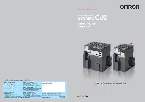
<strong>Programmable</strong> <strong>Controllers</strong><br />
<strong>CJ2</strong>H-CPU6@-EIP<br />
<strong>CJ2</strong>H-CPU6@<br />
Note: Do not use this document to operate the Unit.<br />
OMRON Corporation<br />
Industrial Automation Company<br />
Control Devices Division H.Q.<br />
Automation & Drive Division<br />
Automation Department 1<br />
Shiokoji Horikawa, Shimogyo-ku,<br />
Kyoto, 600-8530 Japan<br />
Tel: (81) 75-344-7084/Fax: (81) 75-344-7149<br />
OMRON ELECTRONICS LLC<br />
One Commerce Drive Schaumburg,<br />
IL 60173-5302 U.S.A.<br />
Tel: (1) 847-843-7900/Fax: (1) 847-843-7787<br />
OMRON ASIA PACIFIC PTE. LTD.<br />
No. 438A Alexandra Road # 05-05/08 (Lobby 2),<br />
Alexandra Technopark, Singapore 119967<br />
Tel: (65) 6835-3011/Fax: (65) 6835-2711<br />
Authorized Distributor:<br />
Throughput Refined at the Microsecond Level<br />
Regional Headquarters<br />
OMRON (CHINA) CO., LTD.<br />
OMRON EUROPE B.V.<br />
Room 2211, Bank of China Tower,<br />
Wegalaan 67-69-2132 JD Hoofddorp<br />
200 Yin Cheng Zhong Road,<br />
The Netherlands<br />
PuDong New Area, Shanghai, 200120, China<br />
Tel: (31)2356-81-300/Fax: (31)2356-81-388 Tel: (86) 21-5037-2222/Fax: (86) 21-5037-2200<br />
OMRON Industrial Automation Global: www.ia.omron.com<br />
© OMRON Corporation 2008 All Rights Reserved.<br />
In the interest of product improvement,<br />
specifications are subject to change without notice.<br />
Printed in Japan<br />
Cat. No. P059-E1-03<br />
0509 (0908)
F-2 CONTENTS<br />
F-3<br />
<strong>SYSMAC</strong>: Enhanced for Greater Reliability<br />
Concepts .........................................................F-2<br />
System Design Guide ......................................... 1<br />
System Configuration ....................................................... 2<br />
Throughput Refined at the Microsecond Level<br />
F o r C e l l C o n t r o l a n d M a c h i n e C o n t r o l<br />
Dimensions ...................................................................... 6<br />
General Specifications .................................................... 9<br />
Performance Specifications ........................................... 10<br />
Function Specifications .................................................. 13<br />
Checking Current Consumption and Power<br />
Consumption ................................................................. 18<br />
Ordering Information ......................................... 19<br />
The <strong>SYSMAC</strong> <strong>CJ2</strong> covers a wide range of applications with improved system<br />
throughput from inputs and processing to outputs.<br />
The application range is also increased through data synchronization between Units.<br />
Basic Configuration Units .............................................. 20<br />
Programming Devices ................................................... 22<br />
Programming Device Connecting Cable ....................... 23<br />
FA Communications Software ....................................... 24<br />
Optional Products and Maintenance Products .............. 25<br />
DIN Track Accessories .................................................. 25<br />
Basic I/O Units ............................................................... 26<br />
Special I/O Units and CPU Bus Units ............................ 30<br />
CJ Series Enhancements<br />
Higher speed for system<br />
throughput from inputs and<br />
processing to outputs.<br />
Stable control with no<br />
fluctuations.<br />
Synchronous Unit<br />
Operation<br />
Advanced motion<br />
control can be<br />
performed easily<br />
and at low cost.<br />
Improved System<br />
Throughput<br />
Higher precision is<br />
provided for machine<br />
operation and<br />
processing quality.<br />
Improved Basic<br />
Performance<br />
The CPU Unit operates<br />
at higher speed and<br />
provides higher<br />
capacity.<br />
A <strong>Programmable</strong> Controller that Inherits<br />
All the Features of the <strong>SYSMAC</strong> CJ1<br />
<strong>Programmable</strong> <strong>Controllers</strong><br />
Windows is a registered trademark of Microsoft Corporation in the USA.<br />
DeviceNet, DeviceNet Safety, and CompoNet are registered trademarks of the ODVA.<br />
Other company names and product names are the trademarks or registered trademarks of their<br />
respective companies.
F-4<br />
Improved<br />
System<br />
Higher Precision for<br />
Machine Operation and<br />
Processing Quality<br />
Lineup of High-speed Units<br />
F o r C e l l C o n t r o l a n d M a c h i n e C o n t r o l<br />
F-5<br />
Throughput<br />
In addition to the greater processing performance of the CPU Unit, OMRON has also improved<br />
the response performance of each Unit. Faster throughput from inputs and processing to<br />
outputs helps to improve equipment tact time and work processing quality.<br />
NEW<br />
Flexible Machine Control with Refined I/O Perform<br />
Direct Processing for High-speed Units with Enhanced Immediate Refreshing<br />
Improve realtime control.<br />
Improved Interrupt Response<br />
• Scheduled interrupt<br />
processing<br />
• Input interrupt<br />
processing<br />
Improved Realtime<br />
Performance for<br />
Immediate Refreshing<br />
• Realtime analog I/O values.<br />
Faster Unit Input Response and Output Response<br />
• ON/OFF response time for Basic I/O Units<br />
• Conversion time (A/D and D/A) for Analog I/O Units<br />
• Positioning start time for Position Control Units<br />
The addition of the immediate refreshing instructions for High-speed Units increases the<br />
I/O throughput speed.<br />
• Analog I/O Direct Conversion Instruction<br />
Conversion for an Analog I/O Unit is immediately executed when a direct conversion instruction<br />
is executed in the CPU Unit. Refreshed data is read and used for control in realtime.<br />
Available<br />
soon.<br />
<strong>CJ2</strong>-CPU<br />
Analog Input Unit:<br />
High-speed type<br />
CJ1W-AD042<br />
Analog Output Unit:<br />
High-speed type<br />
CJ1W-DA042V<br />
7<br />
Times<br />
Faster<br />
From<br />
Immediate refreshing<br />
Input<br />
200 µs<br />
To<br />
Processing<br />
29 µs<br />
29 µs<br />
Direct Note: Time per point.<br />
conversion<br />
Processing<br />
Immediate refreshing<br />
200 µs<br />
Approx. 7 times faster<br />
Output<br />
Improved Interrupt Response for Finer Control with the High-speed Interrupt Function<br />
Input<br />
Output<br />
Conversion<br />
Conversion<br />
Inputs Outputs<br />
• Shorter Minimum Interval for Scheduled Interrupts (100 µs * )<br />
Improved Equipment Performance with Faster Unit I/O Response<br />
• Faster Basic I/O Unit OFF Response Time: 90 µs<br />
Input<br />
<strong>CJ2</strong>-CPU<br />
Fastest<br />
in the<br />
Industry<br />
From<br />
To<br />
100 µs<br />
200 µs<br />
Handle interrupts every 100 µs.<br />
* Supported only for one scheduled interrupt task. Not supported for the peripheral<br />
(USB) port or serial port of the CPU Unit.<br />
Basic I/O Units:<br />
High-speed type<br />
CJ1W- ID212<br />
ID233<br />
Analog Input Unit:<br />
High-speed type<br />
CJ1W-AD042<br />
Analog Output Unit:<br />
High-speed type<br />
CJ1W-DA042V<br />
4<br />
Times<br />
Faster<br />
Fastest<br />
in the<br />
Industry<br />
12<br />
Times<br />
Faster<br />
From<br />
20 µs<br />
To 15 µs<br />
From<br />
To<br />
Input ON<br />
response time<br />
90 µs<br />
• High-speed Analog Conversion: 20 µs per Point (35 µs per Four Points)<br />
Available<br />
soon.<br />
20 µs<br />
Input OFF<br />
response time<br />
12 times faster<br />
Note: Conversion time per point.<br />
4 times faster<br />
400 µs<br />
250 µs<br />
• Faster Interrupt Response Time for Input Interrupts (17 µs * )<br />
<strong>CJ2</strong>-CPU<br />
Applications<br />
Image-processing Inspection<br />
of Electronic Components<br />
Shutter output<br />
Input<br />
From<br />
To<br />
30 µs<br />
Input interrupt response time<br />
17 µs<br />
Input interrupt<br />
response time<br />
* When using the high-speed interrupt function.<br />
High-speed Sorting on Conveyors<br />
Sorting<br />
Interrupt task<br />
Interrupt task<br />
Overhead reduced<br />
by approximately<br />
one half to 17 µs.<br />
• High-speed Positioning Starts in up to 0.1 ms *<br />
Available<br />
soon.<br />
Position Control Units:<br />
High-speed type<br />
CJ1W- NC214<br />
NC234<br />
NC414<br />
NC434<br />
20<br />
Times<br />
Faster<br />
From<br />
To<br />
0.1 ms<br />
20 times faster<br />
2 ms<br />
Note: Starting time for first axis when all axes are stopped.<br />
* When using a <strong>CJ2</strong> CPU Unit.<br />
Workpiece detection<br />
High speed is achieved with no variations from<br />
detecting the workpiece with the Photoelectric<br />
Sensor to activating the camera shutter. Precise,<br />
high-speed inspection is thus possible.<br />
Workpiece detection<br />
Control the processing speed at ultra-high speed without<br />
variations from the sensor input to response output.
F-6<br />
Synchronous<br />
Unit<br />
Operation<br />
Advanced Motion Control with<br />
Low Cost and Building Synchronized Systems<br />
Using Only Ladder Programming<br />
and No Special <strong>Controllers</strong><br />
Easy Operation<br />
The <strong>CJ2</strong> covers a wide range of applications from positioning control to synchronized multi-axis<br />
control, so there is no need to use different <strong>Controllers</strong> depending on the difficulty of the motion<br />
operation. No expensive Motion Control Units are required, and so design efficiency is improved<br />
by sharing the development environment, and inventory management costs are reduced.<br />
F o r C e l l C o n t r o l a n d M a c h i n e C o n t r o l<br />
F-7<br />
NEW<br />
Wide Range of Support from Positioning Control to Synchronized Multi-axis Control<br />
Standardize controllers for motion applications.<br />
Up to<br />
20<br />
axes<br />
NEW<br />
Synchronization from Inputs and Processing to Outputs<br />
Synchronize the CPU Unit with CPU Bus Units and Special I/O Units.<br />
Functionality<br />
Multi-axis<br />
synchronization<br />
Electronic cams<br />
Torque<br />
Tracking<br />
Interpolation<br />
PTP<br />
Low<br />
Ladder language<br />
<strong>CJ2</strong><br />
+<br />
High-speed type of<br />
Position Control Units:<br />
Previous Position<br />
Control Units<br />
Build synchronized systems using only<br />
ladder programming and no special<br />
<strong>Controllers</strong>.<br />
Synchronized control can be<br />
performed for up to 20 axes by using<br />
five Position Control Units.<br />
Programming can also be easily<br />
performed simply by pasting an<br />
electronic cam function block into a<br />
synchronized interrupt task. (See<br />
note.)<br />
Note: The electronic cam function block is provided<br />
with CX-One version 3.1 or the CX-One auto<br />
update for February 2009.<br />
Cost<br />
Servomotor/<br />
Servo Drive<br />
Motion language<br />
Motion Control Units<br />
<strong>CJ2</strong><br />
High<br />
Control cycle<br />
0.5 ms<br />
1 ms<br />
2 ms<br />
4 ms<br />
Available soon.<br />
Position Control Units:<br />
High-speed type<br />
Synchronized<br />
Electronic cam operation for eight axes is<br />
supported using two Position Control Units.<br />
The <strong>CJ2</strong> CPU Units<br />
can be combined<br />
with Position<br />
Control Units to<br />
support advanced<br />
applications.<br />
Encoder<br />
Synchronize the Processing Timing between CPU Bus Units and Special I/O Units.<br />
The <strong>CJ2</strong> CPU Units now support Synchronous Unit Operation in which the CPU Unit synchronizes<br />
the start of processing by the CPU Bus Units and Special I/O Units. This enables using synchronized<br />
data refreshing to share data between the CPU Unit and CPU Bus Units/Special I/O Units and using<br />
synchronous interrupt tasks to process that data. In the future, the range of applications will expand<br />
with the release of more CPU Bus Units and Special I/O Units that support Synchronous Unit<br />
Operation. (These Units are called Synchronous Units).<br />
From<br />
Operation between CPU Unit and CPU Bus Units/<br />
Special I/O Units not synchronized.<br />
CPU Unit<br />
Cyclic<br />
tasks<br />
CPU Bus Unit or<br />
Special I/O Unit<br />
Asynchronous<br />
CPU Bus Unit or<br />
Special I/O Unit<br />
CPU Bus Unit or<br />
Special I/O Unit<br />
To<br />
Fully synchronized operation between CPU Unit and<br />
CPU Bus Units/Special I/O Units.<br />
Cyclic<br />
tasks<br />
CPU Bus Unit or<br />
Special I/O Unit<br />
Synchronized<br />
CPU Bus Unit or<br />
Special I/O Unit<br />
Achieve Application Performance with a Synchronized Operation Cycle at the<br />
Maximum Speed of 1 ms with No Jitter<br />
From<br />
Jitter in I/O Processing between Units<br />
I/O refreshing<br />
CPU Unit<br />
Internal<br />
processing<br />
Internal<br />
processing<br />
CPU Unit<br />
Processing<br />
Internal<br />
processing<br />
Synchronous<br />
interrupt<br />
tasks<br />
Internal<br />
processing<br />
I/O refreshing<br />
Internal<br />
processing<br />
Up to ten Units<br />
Perfect input<br />
timing!<br />
CPU Bus Unit or<br />
Special I/O Unit<br />
Perfect output<br />
timing!<br />
The <strong>CJ2</strong> supports applications that require strict time management, such as electronic cam control, by<br />
using multi-axis control, which minimizes jitter from inputs and processing to outputs.<br />
Internal<br />
processing<br />
Applications<br />
Bottle Filler<br />
Crimping Equipment<br />
Unit A<br />
Unit B<br />
Internal processing<br />
Internal processing<br />
Internal processing<br />
Internal processing<br />
Internal processing<br />
To<br />
Inputs occur at<br />
different times.<br />
Synchronous Unit Operation<br />
Synchronized data refreshing<br />
There is also jitter in<br />
the output timing.<br />
Fixed cycle with no jitter<br />
Control of the conveyor, nozzle, and filling stroke is synchronized.<br />
Encoder<br />
AC Servomotor<br />
R88M-G<br />
AC Servo Drive<br />
R88D-GT<br />
R7D-BP<br />
An electronic cam enables high-precision<br />
synchronized control.<br />
CPU Unit<br />
Synchronous<br />
Unit A<br />
Synchronous<br />
Unit B<br />
Synchronous interrupt task<br />
(e.g., electronic cam control)<br />
Synchronous<br />
interrupt task<br />
Internal processing Internal processing<br />
Internal processing Internal processing<br />
Synchronous<br />
interrupt task<br />
Data is input in the same cycle and at the same time.<br />
There is no jitter in output timing.<br />
Synchronous<br />
interrupt task<br />
Synchronous<br />
interrupt task
F-8<br />
Faster and Higher-capacity<br />
F-9<br />
Improved<br />
Basic<br />
Performance<br />
CPU Units<br />
Data Memory: 832 Kwords,<br />
Basic Instructions: 0.016 µs<br />
High-capacity data memory is in demand to meet the need for quality control for equipment and<br />
products and to provide realtime processing and collection of measurement data. Large program<br />
capacity is also in demand due to the need for improving program reusability through<br />
modularization and structured programming.<br />
F o r C e l l C o n t r o l a n d M a c h i n e C o n t r o l<br />
Greatly Expanded Program Capacity and Data Memory Capacity<br />
High-speed Performance as a Controller<br />
Ample support is provided for programming and data required for complicated control.<br />
The <strong>CJ2</strong> also provides flexible machine control with refined basic performance.<br />
Additions to the Lineup Include Models without<br />
EtherNet/IP, Including Large-capacity Models.<br />
• Program capacity: 400 Ksteps (1.6 times larger than before)<br />
• Data memory capacity:<br />
832 Kwords (2 times larger than before)<br />
• Unit width: 49 mm<br />
NEW<br />
USB port as standard<br />
feature<br />
Memory Card<br />
Ample Instruction Execution Performance for<br />
Machine Control.<br />
The <strong>CJ2</strong> fully responds to customer needs for improved tact time and<br />
increased information handling.<br />
Fast<br />
Fast<br />
System Overhead<br />
Common processing: 100 µs *<br />
Interrupt response: 30 µs<br />
Basic Instructions<br />
LD instruction execution: 0.016 µs<br />
OUT instruction execution: 0.016 µs<br />
Fast<br />
Floating-point Math<br />
SIN processing: 0.59 µs<br />
Floating-point decimal addition<br />
and subtraction: 0.24 µs<br />
* The overhead processing time is<br />
200 µs for the <strong>CJ2</strong>H-CPU6@-EIP.<br />
RS-232C port<br />
Faster Immediate Refreshing<br />
20<br />
Times<br />
Faster<br />
And, All <strong>CJ2</strong> Models Have More Capacity Than CJ1 Models.<br />
In addition, all models have more capacity than the equivalent<br />
CJ1-series models to meet needs for structured programming<br />
and increasing amounts of data.<br />
Increased Capacity over CJ1-series CPU Units<br />
Program<br />
capacity<br />
400 Ksteps<br />
250 Ksteps<br />
150 Ksteps<br />
100 Ksteps<br />
CJ1M/CJ1G/CJ1H Product Lineup<br />
CPU65<br />
CPU65-EIP<br />
CPU66<br />
CPU66-EIP<br />
<strong>CJ2</strong>H<br />
CPU67<br />
CPU67-EIP<br />
Program capacity:<br />
Data memory capacity:<br />
CPU68<br />
CPU68-EIP<br />
49 mm<br />
400 Ksteps<br />
832 Kwords<br />
Immediate refreshing of basic I/O is also faster. Realtime inputs and outputs<br />
during instruction execution are up to 20 times faster than before.<br />
(Example: !LD instruction speed improved from 20 µs to 1 µs)<br />
Fiber Sensor<br />
E3X-DA<br />
Sensor status is<br />
read just prior<br />
to instruction<br />
execution.<br />
Automatic User Memory Recovery<br />
!<br />
!<br />
<strong>CJ2</strong> CPU<br />
High Reliability in Operation<br />
Output<br />
immediately<br />
after instruction<br />
is executed.<br />
Air cylinder<br />
The <strong>CJ2</strong> provides high reliability and dependability with corrective<br />
actions against unforeseen events.<br />
Finer memory production processes have been accompanied by<br />
problems such as bit corruption caused by cosmic rays. With the<br />
<strong>CJ2</strong> CPU Units, corruption in the user program is detected and<br />
the program recovered in realtime before program execution.<br />
This reduces equipment down time by minimizing the number of<br />
times that operation is stopped due to memory errors.<br />
50 Ksteps<br />
30 Ksteps<br />
CPU64<br />
CPU64-EIP<br />
From<br />
Cosmic rays<br />
User program data<br />
is corrupted<br />
Operation is stopped due<br />
to memory error.<br />
To<br />
Cosmic rays<br />
User program data<br />
is corrupted<br />
Data is automatically<br />
restored and normal<br />
operation continues.<br />
64 Kwords 160 Kwords 352 Kwords 448 Kwords 512 Kwords 832 Kwords<br />
Data memory capacity<br />
A memory error occurs and operation stops<br />
to prevent incorrect program execution due<br />
to bit corruption.<br />
If bit corruption occurs because of cosmic<br />
rays or other reason, the correct data will<br />
be instantaneously recovered.
MEMO
System Design Guide<br />
System Configuration ........................................................................................2<br />
Dimensions ........................................................................................................6<br />
General Specifications .......................................................................................9<br />
Performance Specifications .............................................................................10<br />
Function Specifications ....................................................................................13<br />
Checking Current Consumption and Power Consumption ...............................18<br />
1
AC100-240V<br />
INPUT<br />
L1<br />
L2/N<br />
NC<br />
NC<br />
ALARM<br />
OUTPUT<br />
DC30V,50mA<br />
NORMAL:ON<br />
ALARM :OFF<br />
POWER<br />
Years<br />
<strong>SYSMAC</strong><br />
<strong>CJ2</strong>H<br />
CPU64-EIP<br />
PROGRAMMABLE<br />
CONTROLLER<br />
OPEN<br />
SW SETTING<br />
BATTERY<br />
MCPWR<br />
BUSY<br />
RUN<br />
ERR/ALM<br />
INH<br />
PRPHL<br />
COMM<br />
BKUP<br />
PERIPHERAL<br />
PORT<br />
1<br />
x16<br />
100BASE-TX<br />
10BASE-T<br />
MS<br />
NS<br />
COMM<br />
100M<br />
10M<br />
UNIT<br />
No.<br />
NODE<br />
No.<br />
0<br />
x16<br />
IC101<br />
AC100-240V<br />
INPUT<br />
L1<br />
L2/N<br />
NC<br />
NC<br />
AC100-240V<br />
INPUT<br />
L1<br />
L2/N<br />
NC<br />
NC<br />
AC100-240V<br />
INPUT<br />
L1<br />
L2/N<br />
NC<br />
NC<br />
CJ1W-PA205C<br />
POWER<br />
ALARM<br />
OUTPUT<br />
DC30V,50mA<br />
NORMAL:ON<br />
ALARM :OFF<br />
L<br />
+<br />
Years<br />
TEST<br />
CJ1W-PA205C<br />
POWER<br />
ALARM<br />
OUTPUT<br />
DC30V,50mA<br />
NORMAL:ON<br />
ALARM :OFF<br />
L<br />
+<br />
Years<br />
TEST<br />
CJ1W-PA205C<br />
POWER<br />
ALARM<br />
OUTPUT<br />
DC30V,50mA<br />
NORMAL:ON<br />
ALARM :OFF<br />
L<br />
+<br />
Years<br />
TEST<br />
II101<br />
OUT<br />
II101<br />
OUT<br />
II101<br />
OUT<br />
IN<br />
IN<br />
IN<br />
WE70-AP<br />
FA WIRELESS LAN ACCESS POINT<br />
POWER MODE<br />
LAN WIRELESS<br />
WE70-AP<br />
FA WIRELESS LAN ACCESS POINT<br />
POWER MODE<br />
LAN WIRELESS<br />
PA205R<br />
POWER<br />
L1<br />
AC100-240V<br />
INPUT<br />
L2/N<br />
RUN<br />
OUTPUT<br />
AC240V<br />
DC24V<br />
<strong>SYSMAC</strong><br />
CJ1G-CPU44<br />
PROGRAMMABLE<br />
CONTROLLER<br />
OPEN<br />
MCPWR<br />
BUSY<br />
RUN<br />
ERR/ALM<br />
INH<br />
PRPHL<br />
COMM<br />
PERIPHERAL<br />
PORT<br />
System Configuration<br />
■ Basic System<br />
FA Communication Software<br />
<strong>SYSMAC</strong> Gateway<br />
CX-Compolet<br />
FA Wireless Lan Units<br />
WE70<br />
<strong>Programmable</strong> Terminal (PT)<br />
NS Series<br />
Industrial Switching Hubs<br />
WS41-03B<br />
WS41-05B/C<br />
PLC<br />
CJ1 Power Supply Units<br />
CJ1W-PA205C<br />
CJ1W-PA205R<br />
CJ1W-PA202<br />
CJ1W-PD025<br />
CJ1W-PD022<br />
<strong>CJ2</strong> CPU Units<br />
<strong>CJ2</strong>H-CPU6@-EIP<br />
<strong>CJ2</strong>H-CPU6@<br />
CJ1 Battery<br />
CJ1W-BAT01<br />
Ethernet Cable<br />
Commercially available<br />
100Base-TX twisted-pair cable<br />
CPU Rack (Backplane-free Structure)<br />
CJ1 I/O Control Unit<br />
CJ1W-IC101<br />
CJ1 End Cover<br />
CJ1W-TER01<br />
Programming Devices<br />
CJ1W-PA205C<br />
OUT<br />
CX-One Ver.3.@<br />
(e.g., CX-Programmer)<br />
L<br />
+<br />
TEST<br />
USB Cable<br />
Commercially available USB cable<br />
<strong>Programmable</strong> Terminal (PT)<br />
NS Series<br />
Memory Card<br />
HMC-EF@@@<br />
(128 MB, 256 MB, 512 MB)<br />
CJ1 Basic I/O Units<br />
CJ1 Special I/O Units<br />
CJ1 CPU Bus Units<br />
Note: A maximum of 10<br />
Units can be mounted.<br />
CS1 Expansion Cables<br />
CS1W-CN@@3<br />
(30 cm, 70 cm, 2 m, 3 m, 5 m, 10 m, 12 m)<br />
Expansion Rack (Backplane-free Structure)<br />
RS-232C Cable for PT<br />
XW2Z-200T/500T<br />
CJ1 I/O Interface Unit<br />
RS-232C Cable for<br />
Personal Computer<br />
CJ1W-II101<br />
XW2Z-200S/500S-CV<br />
RS-422A Adapter<br />
CJ1W-CIF11<br />
2 <strong>Programmable</strong> <strong>Controllers</strong> <strong>SYSMAC</strong> <strong>CJ2</strong>
■ Configuration Units<br />
● DC Input Unit<br />
CJ1W-ID201<br />
● AC Input Unit<br />
CJ1W-IA201<br />
CJ1 Basic I/O Units<br />
8-point Units 16-point Units 32-point Units 64-point Units<br />
● Relay Contact Output Unit<br />
(independent commons)<br />
CJ1W-OC201<br />
● Triac Output Unit<br />
CJ1W-OA201<br />
● Transistor Output Units<br />
CJ1W-OD201<br />
CJ1W-OD203<br />
CJ1W-OD202<br />
CJ1W-OD204<br />
● DC Input Unit<br />
CJ1W-ID211<br />
CJ1W-ID212<br />
● AC Input Unit<br />
CJ1W-IA111<br />
● Relay Contact Output Unit<br />
CJ1W-OC211<br />
● Transistor Output Units<br />
CJ1W-OD211<br />
CJ1W-OD213<br />
CJ1W-OD212<br />
--- ---<br />
---<br />
● Interrupt Input Unit<br />
CJ1W-INT01<br />
● Quick-response Input Unit<br />
CJ1W-IDP01<br />
Input Units<br />
● DC Input Unit<br />
CJ1W-ID231<br />
CJ1W-ID232<br />
CJ1W-ID233<br />
Output Units<br />
I/O Units<br />
Other Units<br />
● Transistor Output Units<br />
CJ1W-OD231<br />
CJ1W-OD233<br />
CJ1W-OD234<br />
CJ1W-OD232<br />
(16 inputs, 16 outputs)<br />
● DC Input/Transistor Output Units<br />
CJ1W-MD231<br />
CJ1W-MD233<br />
CJ1W-MD232<br />
---<br />
● DC Input Unit<br />
CJ1W-ID261<br />
CJ1W-ID262<br />
● Transistor Output Units<br />
CJ1W-OD261<br />
CJ1W-OD263<br />
CJ1W-OD262<br />
32 inputs, 32 outputs<br />
● DC Input/Transistor Output Units<br />
CJ1W-MD261<br />
CJ1W-MD263<br />
32 inputs, 32 outputs<br />
● TTL I/O Unit<br />
CJ1W-MD563<br />
● B7A Interface Units<br />
(64 inputs)<br />
CJ1W-B7A14<br />
(64 outputs)<br />
CJ1W-B7A04<br />
(32 inputs, 32 outputs)<br />
CJ1W-B7A22<br />
CJ1 Special I/O Units and CPU Bus Units<br />
■ Process I/O Units<br />
● Isolated-type Units with Universal Inputs<br />
CJ1W-PH41U<br />
CJ1W-AD04U<br />
● Isolated-type Thermocouple Input Units<br />
CJ1W-PTS15<br />
CJ1W-PTS51<br />
● Isolated-type Resistance<br />
Thermometer Input Units<br />
CJ1W-PTS16<br />
CJ1W-PTS52<br />
● Isolated-type DC Input Unit<br />
CJ1W-PDC15<br />
■ Analog I/O Units<br />
● Analog Input Units<br />
CJ1W-AD042 Available soon<br />
CJ1W-AD081-V1<br />
CJ1W-AD041-V1<br />
● Analog Output Units<br />
CJ1W-DA042V Available soon<br />
CJ1W-DA08V<br />
CJ1W-DA08C<br />
CJ1W-DA041<br />
CJ1W-DA021<br />
● Analog I/O Units<br />
CJ1W-MAD42<br />
■ Temperature Control Units<br />
CJ1W-TC001, CJ1W-TC002<br />
CJ1W-TC003, CJ1W-TC004<br />
CJ1W-TC101, CJ1W-TC102<br />
CJ1W-TC103, CJ1W-TC104<br />
■ High-speed Counter Units<br />
CJ1W-CT021<br />
■ Position Control Units<br />
● Position Control Units<br />
(High-speed type)<br />
CJ1W-NC214<br />
Available soon<br />
CJ1W-NC414 Available soon<br />
CJ1W-NC234 Available soon<br />
CJ1W-NC434 Available soon<br />
● Position Control Units<br />
CJ1W-NC113<br />
CJ1W-NC213<br />
CJ1W-NC413<br />
CJ1W-NC133<br />
CJ1W-NC233<br />
CJ1W-NC433<br />
■ MECHATROLINK II-compatible<br />
Position Control Unit<br />
CJ1W-NC271<br />
CJ1W-NC471<br />
CJ1W-NCF71<br />
CJ1W-NCF71-MA<br />
■ MECHATROLINK II-compatible<br />
Motion Control Unit<br />
CJ1W-MCH71<br />
■ Serial Communications Units<br />
CJ1W-SCU21-V1<br />
CJ1W-SCU31-V1<br />
CJ1W-SCU41-V1<br />
■ EtherNet/IP Unit<br />
CJ1W-EIP21<br />
■ Ethernet Unit<br />
CJ1W-ETN21<br />
■ Controller Link Units<br />
CJ1W-CLK23<br />
■ FL-net Unit<br />
CJ1W-FLN22<br />
■ DeviceNet Unit<br />
CJ1W-DRM21<br />
■ CompoNet Master Unit<br />
CJ1W-CRM21<br />
■ CompoBus/S Master Unit<br />
CJ1W-SRM21<br />
■ ID Sensor Units<br />
CJ1W-V680C11<br />
CJ1W-V680C12<br />
CJ1W-V600C11<br />
CJ1W-V600C12<br />
■ High-speed Data Storage Unit<br />
CJ1W-SPU01-V2<br />
Note: MECHATROLINK II is a registered trademark of the MECHATROLINK Members Association.<br />
<strong>Programmable</strong> <strong>Controllers</strong> <strong>SYSMAC</strong> <strong>CJ2</strong> 3
■ CJ-series CPU Racks<br />
A CJ-series CPU Rack consists of a CPU Unit, Power Supply Unit, Configuration Units (Basic I/O Units, Special I/O Units, and CPU Bus<br />
Units), and an End Cover.<br />
Power Supply Unit<br />
CJ1W-P@@@ (@)<br />
CPU Unit<br />
<strong>CJ2</strong>H-CPU6@-EIP<br />
<strong>CJ2</strong>H-CPU6@<br />
I/O Control Unit<br />
CJ1W-IC101<br />
(Required only when connecting<br />
to an Expansion Rack.)<br />
End Cover<br />
CJ1W-TER01<br />
(One End Cover is provided as a standard<br />
accessory with the CPU Unit.)<br />
CPU Rack<br />
CJ-series Basic I/O Units<br />
CJ-series Special I/O Units<br />
CJ-series CPU Bus Units<br />
Total: 10 Units max<br />
● Required Units<br />
Rack Unit name Required number of Units<br />
Power Supply Unit 1<br />
CPU Unit 1<br />
CPU Rack<br />
I/O Control Unit<br />
Number of Configuration Units<br />
End Cover<br />
Required only for mounting to an Expansion Rack.<br />
10 max. (Same for all models of CPU Unit.)<br />
(The number of Basic I/O Units, Special I/O Units, and CPU Bus Units can be varied. The number does<br />
not include the I/O Control Unit.)<br />
1 (Included with CPU Unit.)<br />
● Types of Units<br />
In the <strong>SYSMAC</strong> CJ Series, Units are classified into the following three types. The number of Racks differs depending on the type.<br />
Type Appearance (example) Description Unit recognition method No. of Units<br />
Basic I/O Units Units with contact inputs and contact outputs. Recognized by the CPU Unit according<br />
to the position of the Rack and<br />
slot.<br />
No restrictions.<br />
Special I/O<br />
Units<br />
Special I/O Units provide more advanced functions<br />
than do Basic I/O Units, including I/O other than<br />
contact inputs and contact outputs.<br />
Examples of Special I/O Units are Analog I/O<br />
Units and High-speed Counter Units. They differ<br />
from CPU Bus Units (including Network Communications<br />
Units) in having a smaller area for<br />
exchanging data with the CPU Unit.<br />
Recognized by the CPU Unit according<br />
to the unit number (0 to 95) set<br />
with the rotary switches on the front<br />
panel.<br />
A maximum of 96 Units<br />
can be connected. (Multiple<br />
unit numbers are allocated<br />
per Unit,<br />
depending on the model<br />
and settings.)<br />
CPU Bus Units<br />
CPU Bus Units exchange data with the CPU Unit<br />
via the CPU Bus.<br />
Examples of CPU Bus Units are Network Communications<br />
Units and Serial Communications Units.<br />
They differ from Special I/O Units in having a<br />
larger area for exchanging data with the CPU Unit.<br />
Recognized by the CPU Unit according<br />
to the unit number (0 to F) set with<br />
the rotary switch on the front panel.<br />
A maximum of 16 Units<br />
can be mounted. *<br />
* <strong>CJ2</strong>H-CPU6@-EIP : A maximum of 15 Units can be mounted. (The built-in EtherNet/IP port on the CPU Unit must be allocated as one of the CPU Bus Units.)<br />
4 <strong>Programmable</strong> <strong>Controllers</strong> <strong>SYSMAC</strong> <strong>CJ2</strong>
■ CJ-series Expansion Racks<br />
A CJ-series Expansion Rack consists of a Power Supply Unit, an I/O Interface Unit, Configuration Units (Basic I/O Units, Special I/O<br />
Units, and CPU Bus Units), and an End Cover.<br />
CPU Unit<br />
<strong>CJ2</strong>H-CPU@@-EIP<br />
Power Supply Unit<br />
CJ1W-P@@@(@)<br />
I/O Control Unit<br />
CJ1W-IC101<br />
CPU Rack<br />
Power Supply Unit<br />
CJ1W-P@@@(@)<br />
I/O Interface Unit<br />
CJ1W-II101<br />
Configuration Units: 10 max.<br />
I/O Connecting Cable<br />
CS1W-CN@@3<br />
Expansion<br />
Rack<br />
Total<br />
cable<br />
length<br />
≤ 12 m<br />
I/O Interface Unit<br />
CJ1W-II101<br />
Power Supply Unit<br />
CJ1W-P@@@(@)<br />
Configuration Units: 10 max.<br />
I/O Connecting Cable<br />
CS1W-CN@@3<br />
Expansion<br />
Rack<br />
Number of Expansion Racks:<br />
Up to 3 Expansion Racks can be connected.<br />
I/O Interface Unit<br />
CJ1W-II101<br />
Power Supply Unit<br />
CJ1W-P@@@(@)<br />
Configuration Units: 10 max.<br />
I/O Connecting Cable<br />
CS1W-CN@@3<br />
Expansion<br />
Rack<br />
Configuration Units: 10 max.<br />
● Required Units<br />
Rack Unit name Required number of Units<br />
CPU Rack<br />
Expansion<br />
Rack<br />
I/O Control Unit<br />
One Unit. Required only when an Expansion Rack is used. Mount the I/O Control Unit immediately to the right<br />
of the CPU Unit. (See note 1.)<br />
Power Supply Unit<br />
One Unit<br />
I/O Interface Unit One Unit. Mount the I/O Interface Unit immediately to the right of the Power Supply Unit. (See note 2.)<br />
Number of Configuration Units<br />
Ten Units max. (The number of Basic I/O Units, Special I/O Units, and CPU Bus Units can be varied.<br />
This number does not include the I/O Interface Unit.)<br />
End Cover<br />
One (Included with the I/O Interface Unit.)<br />
Note 1. Mounting the I/O Control Unit in any other location may cause faulty operation.<br />
2. Mounting the I/O Interface Unit in any other location may cause faulty operation.<br />
● Maximum Number of Configuration Units That Can Be Mounted<br />
CPU Unit Model Total Units No. of Units on CPU Rack No. of Expansion Racks<br />
<strong>CJ2</strong>H <strong>CJ2</strong>H-CPU68 (-EIP) 40 10 per Rack * 3 Racks x 10 Units<br />
<strong>CJ2</strong>H-CPU67 (-EIP)<br />
<strong>CJ2</strong>H-CPU66 (-EIP)<br />
<strong>CJ2</strong>H-CPU65 (-EIP)<br />
<strong>CJ2</strong>H-CPU64 (-EIP)<br />
* Up to night Units can be connected to a <strong>CJ2</strong>H-CPU6@-EIP CPU Units.<br />
<strong>Programmable</strong> <strong>Controllers</strong> <strong>SYSMAC</strong> <strong>CJ2</strong> 5
<strong>SYSMAC</strong><br />
<strong>CJ2</strong>H<br />
CPU64-EIP<br />
PROGRAMMABLE<br />
CONTROLLER<br />
OPEN<br />
SW SETTING<br />
BATTERY<br />
MCPWR<br />
BUSY<br />
RUN<br />
ERR/ALM<br />
INH<br />
PRPHL<br />
COMM<br />
BKUP<br />
PERIPHERAL<br />
PORT<br />
1<br />
x16<br />
100BASE-TX<br />
10BASE-T<br />
MS<br />
NS<br />
COMM<br />
100M<br />
10M<br />
UNIT<br />
No.<br />
NODE<br />
No.<br />
0<br />
x16<br />
Dimensions<br />
Note: Units are in mm unless specified otherwise.<br />
■ Product Dimensions<br />
W<br />
90<br />
65<br />
27<br />
35.4<br />
27.6<br />
Example Rack Widths using CJ1WPA202 Power Supply Unit (AC, 14 W)<br />
No. of Units<br />
mounted with<br />
31-mm width<br />
Rack width (mm)<br />
With <strong>CJ2</strong>H-CPU6@-EIP<br />
With <strong>CJ2</strong>H-CPU6@<br />
1 170.5 139.5<br />
2 201.5 170.5<br />
3 232.5 201.5<br />
4 263.5 232.5<br />
5 294.5 263.5<br />
6 325.5 294.5<br />
7 356.5 325.5<br />
8 387.5 356.5<br />
9 418.5 387.5<br />
10 449.5 418.5<br />
Power Supply Units, CPU Units, and End Covers<br />
Unit/product Model Width<br />
CJ1W-PA205C 80<br />
CJ1W-PA205R 80<br />
Power Supply Unit<br />
CJ1W-PA202 45<br />
CJ1W-PD025 60<br />
CJ1W-PD022 27<br />
CPU Unit<br />
<strong>CJ2</strong>H-CPU6@-EIP 79.8<br />
<strong>CJ2</strong>H-CPU6@ 48.8<br />
End Cover CJ1W-TER01 14.7<br />
Power Supply Units<br />
CPU Units<br />
<strong>CJ2</strong>H-CPU6@-EIP<br />
CPU Units<br />
<strong>CJ2</strong>H-CPU6@<br />
End Cover<br />
(included with CPU Units)<br />
2.7<br />
66.2<br />
2.7<br />
66.2<br />
90<br />
90<br />
90<br />
90<br />
W<br />
65<br />
81.6<br />
14.7<br />
W=27: CJ1W-PD022<br />
W=45: CJ1W-PA202<br />
W=80: CJ1W-PA205R<br />
CJ1W-PA205C<br />
W=60: CJ1W-PD025<br />
2.7<br />
79.8<br />
65<br />
74.5<br />
2.7<br />
48.75<br />
65<br />
74.5<br />
RS-422A Adapter<br />
CJ1W-CIF11<br />
38.8<br />
34<br />
● Units of Width 20 mm<br />
Unit/product Model Width<br />
I/O Control Unit<br />
CJ1W-IC101<br />
32-point Basic I/O Units<br />
CJ1W-ID231/232/233<br />
CJ1W-OD231/232/233/234<br />
CJ1W-B7A22<br />
B7A Interface Unit<br />
CJ1W-B7A14<br />
20<br />
CJ1W-B7A04<br />
CompoBus/S Master Unit CJ1W-SRM21<br />
Space Unit<br />
CJ1W-SP001<br />
● I/O Control Unit<br />
2.7<br />
(140)<br />
68<br />
● 32-Point I/O Units (CJ1W-ID223@/OD23@)<br />
Fujitsu connector<br />
2.7<br />
(112.5)<br />
MIL connector<br />
90<br />
90<br />
2.7<br />
20<br />
65<br />
69.3<br />
2.7<br />
20<br />
65<br />
66.5<br />
65<br />
83.6<br />
6 <strong>Programmable</strong> <strong>Controllers</strong> <strong>SYSMAC</strong> <strong>CJ2</strong>
● Units of Width 31 mm<br />
Unit Model Width<br />
I/O Interface Unit<br />
8/16-point Basic I/O Units<br />
CJ1W-II101<br />
CJ1W-ID201<br />
CJ1W-ID211/212<br />
CJ1W-IA111/201<br />
CJ1W-OD20@<br />
CJ1W-OD211/212/213<br />
CJ1W-OC201/211<br />
CJ1W-OA201<br />
32-point Basic I/O Units<br />
CJ1W-MD231<br />
CJ1W-MD232/233<br />
64-point Basic I/O Units<br />
CJ1W-ID261<br />
CJ1W-OD261<br />
CJ1W-MD261<br />
CJ1W-ID262<br />
CJ1W-OD262/263<br />
CJ1W-MD263<br />
CJ1W-MD563<br />
Interrupt Input Unit<br />
CJ1W-INT01<br />
Quick-response Input Unit CJ1W-IDP01<br />
Analog I/O Units<br />
CJ1W-AD@@@ (-V1)<br />
CJ1W-DA@@@ (@)<br />
CJ1W-MAD42<br />
CJ1W-PH41U<br />
Process Input Units<br />
CJ1W-AD04U<br />
31<br />
CJ1W-PTS51/52/15/16<br />
CJ1W-PDC15<br />
Temperature Control Units CJ1W-TC@@@<br />
CJ1W-NC113/133<br />
Position Control Units CJ1W-NC213/233<br />
CJ1W-NC413/433<br />
MECHATROLINK-II compatible<br />
Position Control Unit<br />
CJ1W-NCF71<br />
High-speed Counter Unit CJ1W-CT021<br />
CJ1W-V680C11<br />
ID Sensor Units<br />
CJ1W-V680C12<br />
CJ1W-V600C11<br />
CJ1W-V600C12<br />
Controller Link Units CJ1W-CLK23<br />
Serial Communications<br />
Units<br />
EtherNet/IP Unit<br />
Ethernet Unit<br />
DeviceNet Unit<br />
CompoNet Master Unit<br />
FL-net Unit<br />
CJ1W-SCU41-V1<br />
CJ1W-SCU21-V1<br />
CJ1W-SCU31-V1<br />
CJ1W-EIP21<br />
CJ1W-ETN21<br />
CJ1W-DRM21<br />
CJ1W-CRM21<br />
CJ1W-FLN22<br />
● I/O Interface Unit<br />
2.7<br />
90<br />
2.7<br />
31<br />
(140)<br />
68<br />
65<br />
69.3<br />
● 64-point Basic I/O Units and 32-point Basic I/O Units (CJ1W-MD23@)<br />
2.7<br />
90<br />
2.7<br />
● Special I/O Units and CPU Bus Units<br />
2.7<br />
90<br />
2.7<br />
31<br />
31<br />
Fujitsu connector<br />
65<br />
66.5<br />
(112.5)<br />
● 8/6-point Basic I/O Units,<br />
Interrupt Input Unit, and Highspeed<br />
Input Unit<br />
2.7<br />
90<br />
2.7<br />
MIL connector<br />
65<br />
83.6<br />
31 65<br />
89<br />
● Unit of Width 51 mm<br />
Unit Model Width<br />
<strong>SYSMAC</strong> SPU<br />
(High-speed Data Storage<br />
Unit)<br />
Position Control Units<br />
(High-speed type)<br />
CJ1W-SPU01-V2<br />
CJ1W-NC214/234<br />
51<br />
● Unit of Width 62 mm<br />
Unit Model Width<br />
Position Control Units<br />
(High-speed type)<br />
CJ1W-NC414/434 62<br />
● <strong>SYSMAC</strong> SPU (High-speed Data Storage Unit)<br />
CJ1W-SPU01-V2<br />
2.7<br />
90<br />
2.7<br />
51 9<br />
65<br />
<strong>Programmable</strong> <strong>Controllers</strong> <strong>SYSMAC</strong> <strong>CJ2</strong> 7
<strong>SYSMAC</strong><br />
<strong>CJ2</strong>H<br />
CPU64-EIP<br />
PROGRAMMABLE<br />
CONTROLLER<br />
OPEN<br />
SW SETTING<br />
BATTERY<br />
MCPWR<br />
BUSY<br />
RUN<br />
ERR/ALM<br />
INH<br />
PRPHL<br />
COMM<br />
BKUP<br />
PERIPHERAL<br />
PORT<br />
1<br />
x16<br />
100BASE-TX<br />
10BASE-T<br />
MS<br />
NS<br />
COMM<br />
100M<br />
10M<br />
UNIT<br />
No.<br />
NODE<br />
No.<br />
0<br />
x16<br />
● Unit of Width 79.8 mm<br />
Unit Model Width<br />
MECHATROLINK-II compatible<br />
Motion Control Unit<br />
CJ1W-MCH71 79.8<br />
● MECHATROLINK-II compatible Motion Control Unit<br />
CJ1W-MCH71<br />
90<br />
79.8 65<br />
70.9<br />
■ Mounting Dimensions<br />
■ Mounting Height<br />
27.5<br />
35<br />
27.5<br />
65<br />
90<br />
A<br />
The mounting height of CJ-series CPU Racks and Expansion<br />
Racks is from 81.6 to 89.0 mm depending on the Units that are<br />
mounted.<br />
Additional height is required to connect Programming Devices<br />
(e.g., CX-Programmer) and Cables. Be sure to allow sufficient<br />
mounting height.<br />
DIN Track model number<br />
PFP-100N2<br />
PFP-100N<br />
FPP-50N<br />
A<br />
16 mm<br />
7.3 mm<br />
7.3 mm<br />
Approx. 100 to 150 mm<br />
81.6 to 89.0 mm<br />
Note: Consider the following points when expanding the configuration:<br />
The total length of I/O Connecting Cable must not exceed 12 m.<br />
I/O Connecting Cables require the bending radius indicated below.<br />
● CJ-series Connecting Cable<br />
R<br />
R ≥ 69 mm<br />
Note: Outer diameter of cable: 8.6 mm.<br />
8 <strong>Programmable</strong> <strong>Controllers</strong> <strong>SYSMAC</strong> <strong>CJ2</strong>
General Specifications<br />
Item<br />
<strong>CJ2</strong>H-<br />
CPU64 (-EIP) CPU65 (-EIP) CPU66 (-EIP) CPU67 (-EIP) CPU68 (-EIP)<br />
Enclosure<br />
Mounted in a panel<br />
Grounding<br />
Less than 100 Ω<br />
CPU Rack Dimensions <strong>CJ2</strong>H-CPU6@-EIP : 90 mm × 65 mm × 80 mm (H × D × W)<br />
<strong>CJ2</strong>H-CPU6@ : 90 mm × 65 mm × 49 mm (H × D × W)<br />
Weight<br />
<strong>CJ2</strong>H-CPU6@-EIP : 280 g or less<br />
<strong>CJ2</strong>H-CPU6@ : 190 g or less<br />
Current Consumption<br />
<strong>CJ2</strong>H-CPU6@-EIP : 5 VDC, 0.82 A<br />
<strong>CJ2</strong>H-CPU6@ : 5 VDC, 0.42 A<br />
Use<br />
Ambient Operating Temperature 0 to 55°C<br />
Environment Ambient Operating Humidity 10% to 90%<br />
Atmosphere<br />
Must be free from corrosive gases.<br />
Ambient Storage Temperature −20 to 70°C (excluding battery)<br />
Altitude<br />
2,000 m or less<br />
Pollution Degree 2 or less: Conforms to JIS B3502 and IEC 61131-2.<br />
Noise Immunity 2 kV on power supply line (Conforms to IEC 61000-4-4.)<br />
Overvoltage Category Category II: Conforms to JIS B3502 and IEC 61131-2.<br />
EMC Immunity Level<br />
Zone B<br />
Vibration Resistance<br />
Conforms to JIS C60068-2-6.<br />
5 to 8.4 Hz with 3.5-mm amplitude, 8.4 to 150 Hz<br />
Acceleration of 9.8 m/s 2 for 100 min in X, Y, and Z directions (10 sweeps of 10 min each = 100 min total)<br />
Shock Resistance<br />
Conforms to JIS C60068-2-27.<br />
147 m/s 2 , 3 times in X, Y, and Z directions (100 m/s 2 for Relay Output Units)<br />
Battery Life 5 years at 25°C<br />
Model<br />
CJ1W-BAT01<br />
Applicable Standards<br />
Conforms to cULus and EC Directives.<br />
<strong>Programmable</strong> <strong>Controllers</strong> <strong>SYSMAC</strong> <strong>CJ2</strong> 9
Performance Specifications<br />
Item<br />
<strong>CJ2</strong>H-<br />
CPU64 (-EIP) CPU65 (-EIP) CPU66 (-EIP) CPU67 (-EIP) CPU68 (-EIP)<br />
User Memory 50K steps 100K steps 150K steps 250K steps 400K steps<br />
I/O Bits<br />
2,560 bits<br />
Processing Speed Overhead Processing Time Normal Mode: <strong>CJ2</strong>H-CPU6@-EIP : 200 μs *1<br />
<strong>CJ2</strong>H-CPU6@ : 100 μs<br />
Execution Time<br />
Basic Instructions: 0.016 μs min.;<br />
Special Instructions: 0.048 μs min.<br />
Interrupts I/O Interrupts and External<br />
Interrupts<br />
Interrupt task startup time: 17 μs or 26 μs *2 (30 μs for unit version 1.0)<br />
Return times to cyclic tasks: 8 μs or 11 μs *2 (15 μs for unit version 1.0)<br />
Scheduled Interrupts Interrupt task startup time: 13 μs or 22 μs *2 (27 μs for unit version 1.0)<br />
Return times to cyclic tasks: 8 μs or 11 μs *2 (15 μs for unit version 1.0)<br />
Maximum Number of Connectable Units<br />
Total per CPU Rack or Expansion Rack: 10 Units max.;<br />
Total per PLC: 40 Units max.<br />
Maximum Number of Expansion Racks<br />
3 max.<br />
CIO Area I/O Area 2,560 bits (160 words): Words CIO 0000 to CIO 0159<br />
Link Area 3,200 bits (200 words): Words CIO 1000 to CIO 1199<br />
Synchronous Data Refresh Area 1,536 bits (96 words): Words CIO 1200 to CIO 1295<br />
CPU Bus Unit Area 6,400 bits (400 words): Words CIO 1500 to CIO 1899<br />
Special I/O Unit Area 15,360 bits (960 words): Words CIO 2000 to CIO 2959<br />
DeviceNet Area 9,600 bits (600 words): Words CIO 3200 to CIO 3799<br />
Internal I/O Area 3,200 bits (200 words): Words CIO 1300 to CIO 1499<br />
37,504 bits (2,344 words): Words CIO 3800 to CIO 6143<br />
Cannot be used for external I/O.<br />
Work Area<br />
8,192 bits (512 words): Words W000 to W511<br />
Cannot be used for external I/O.<br />
Holding Area<br />
8,192 bits (512 words): Words H000 to H511<br />
Bits in this area maintain their ON/OFF status when PLC is turned OFF or operating mode is changed.<br />
Words H512 to H1535: These words can be used only for function blocks. They can be used only for<br />
function block instances (i.e., they are allocated only for internal variables in function blocks).<br />
Auxiliary Area<br />
Read-only: 31,744 bits (1,984 words)<br />
• 7,168 bits (448 words): Words A0 to A447<br />
• 24,576 bits (1,536 words): Words A10000 to A11535<br />
Read/write: 16,384 bits (1,024 words) in words A448 to A1471<br />
Temporary Area<br />
16 bits: TR0 to TR15<br />
Timer Area<br />
4,096 timer numbers (T0000 to T4095 (separate from counters))<br />
Counter Area<br />
4,096 counter numbers (C0000 to C4095 (separate from timers))<br />
DM Area 32k words *3<br />
DM Area words for Special I/O Units: D20000 to D29599 (100 words × 96 Units)<br />
DM Area words for CPU Bus Units: D30000 to D31599 (100 words × 16 Units)<br />
EM Area 32k words/bank × 25 banks max.: E00_00000 to E18_32767 max. *3<br />
Index Registers<br />
Cyclic Task Flag Area<br />
Memory Card<br />
Operating Modes<br />
Execution Mode<br />
Force-set/reset Enabled<br />
Banks *4<br />
32K words × 4<br />
banks<br />
32K words × 4<br />
banks<br />
*1. The following times are added if EtherNet/IP data tag links are used for the <strong>CJ2</strong>H-CPU6@-EIP.<br />
Normal operation: 100 μs + Number of transfer words x 0.33 μs<br />
High-speed interrupt enabled: 100 μs + Number of transfer words x 0.87 μs<br />
*2. This applies when High-speed interrupt function is used.<br />
*3. Bits in the EM Area can be addressed either by bit or by word.<br />
*4. Force-setting/resetting is possible only in the areas specified for automatic address allocation.<br />
32K words × 10<br />
banks<br />
32K words × 15<br />
banks<br />
32K words × 25<br />
banks<br />
EM3 EM3 EM6 to EM9 EM7 to EME EM11 to EM18<br />
IR0 to IR15<br />
These are special registers for storing PLC memory addresses for indirect addressing. (Index<br />
Registers can be set so that they are unique in each task or so that they are shared by all tasks.)<br />
128 flags<br />
128 MB, 256 MB, or 512 MB<br />
PROGRAM Mode: Programs are not executed. Preparations can be executed prior to program<br />
execution in this mode.<br />
MONITOR Mode: Programs are executed, and some operations, such as online editing, and<br />
changes to present values in I/O memory, are enabled in this<br />
mode.<br />
RUN Mode: Programs are executed. This is the normal operating mode.<br />
Normal Mode<br />
10 <strong>Programmable</strong> <strong>Controllers</strong> <strong>SYSMAC</strong> <strong>CJ2</strong>
Item<br />
*5. Network symbols can be used only with the <strong>CJ2</strong>H-CPU6@-EIP.<br />
*6. This data type cannot be used in Function blocks.<br />
*7. This data type can be used only in Function blocks.<br />
<strong>CJ2</strong>H-<br />
CPU64 (-EIP) CPU65 (-EIP) CPU66 (-EIP) CPU67 (-EIP) CPU68 (-EIP)<br />
Programming Languages<br />
Ladder Logic (LD),<br />
Sequential Function Charts (SFC),<br />
Structured Text (ST), and<br />
Instruction Lists (IL)<br />
Function Blocks Maximum number of definitions 2,048<br />
Maximum number of instances 2,048<br />
Tasks Type of Tasks Cyclic tasks<br />
Interrupt tasks (Power OFF interrupt tasks, scheduled interrupt tasks, I/O interrupt tasks, and<br />
external interrupt tasks)<br />
Number of Tasks Cyclic tasks: 128<br />
Interrupt tasks: 256<br />
(Interrupt tasks can be defined as cyclic tasks to create extra cyclic tasks. Therefore, the total<br />
number of cyclic tasks is actually 384 max.)<br />
Symbols<br />
(Variables)<br />
Type of Symbols<br />
Data Type of Symbols<br />
• Local symbols: Can be used only within a single task in the PLC.<br />
• Global symbols: Can be used in all tasks in the PLC.<br />
• Network symbols (tags) *5: I/O memory in the CPU Unit can be externally accessed using<br />
symbols, depending on parameter settings.<br />
• BOOL (bit)<br />
• UINT (one-word unsigned binary)<br />
• UDINT (two-word unsigned binary)<br />
• ULINT (four-word unsigned binary)<br />
• INT (one-word signed binary)<br />
• DINT (two-word signed binary)<br />
• LINT (four-word signed binary)<br />
• UINT BCD (one-word unsigned BCD) *6<br />
• UDINT BCD (two-word unsigned BCD) *6<br />
• ULINT BCD (four-word unsigned BCD) *6<br />
• REAL (two-word floating-point)<br />
• LREAL (four-word floating-point)<br />
• CHANNEL (word)<br />
• NUMBER (constant or number)<br />
• WORD (one-word hexadecimal)<br />
• DWORD (two-word hexadecimal)<br />
• LWORD (four-word hexadecimal)<br />
• STRING (1 to 255 ASCII characters)<br />
• TIMER *7<br />
• COUNTER *7<br />
32k words<br />
One-dimensional arrays<br />
32,000 elements max.<br />
20,000 max.<br />
Maximum Size of Symbol<br />
Array Symbols (Array Variables)<br />
Number of Array Elements<br />
Number of Registrable Network Symbols<br />
(Tags) *5<br />
Length of Network Symbol (Tag) Name 255 bytes max.<br />
*5<br />
Encoding of Network Symbols (Tags) *5 UTF-8<br />
Data Tracing Memory Capacity 8,000 words 16,000 words 32,000 words<br />
(Up to 32k words x 25 banks when EM is specified in CX-Programmer)<br />
Number of Samplings Bits = 31, one-word data =16, two-word data = 8, four-word data = 4<br />
Sampling Cycle<br />
1 to 2,550 ms (Unit: 1 ms)<br />
Trigger Conditions<br />
File Memory<br />
Source/Comment<br />
Memory<br />
Delay Value<br />
Function block program memory,<br />
comment file, program index file, symbol<br />
tables<br />
ON/OFF of specified bit<br />
Data comparison of specified word<br />
Data size: 1 word, 2 words, 4 words<br />
Comparison Method: Equals (=), Greater Than (>), Greater Than or Equals (≥), Less Than (
Communic<br />
ations<br />
Item<br />
<strong>CJ2</strong>H-<br />
CPU64 (-EIP) CPU65 (-EIP) CPU66 (-EIP) CPU67 (-EIP) CPU68 (-EIP)<br />
Logical Ports for Logical Ports<br />
8 ports (Used for SEND, RECV, CMND, PMCR, TXDU, and RXDU instructions.)<br />
Communications Extended Logical Ports 64 ports (Used for SEND2, RECV2, CMND2, and PMCR2 instructions.)<br />
CIP<br />
Class 3 (Number of Number of connections: 64<br />
Communications Connections)<br />
Specification UCMM (Non-connection Maximum number of clients that can communicate at the same time: 32<br />
Type)<br />
Maximum number of servers that can communicate at the same time: 40<br />
Peripheral (USB) Port<br />
USB 2.0-compliant B-type connector<br />
Baud Rate<br />
12 Mbps max.<br />
Transmission Distance<br />
5 m max.<br />
Serial Port<br />
Interface: Conforms to EIA RS-232C.<br />
Communications Method<br />
Half-duplex<br />
Synchronization Method<br />
Start-stop<br />
Baud Rate<br />
0.3, 0.6, 1.2, 2.4, 4.8, 9.6, 19.2, 38.4, 57.6, or 115.2 (kbps)<br />
Transmission Distance<br />
15 m max.<br />
EtherNet/IP Port *8 ---<br />
Media Access Method<br />
CSMA/CD<br />
Modulation<br />
Baseband<br />
Transmission Paths<br />
Star<br />
Baud Rate<br />
100 Mbps (100Base-TX)<br />
Transmission Media<br />
Shielded twisted-pair (STP) cable; Categories: 5, 5e<br />
Transmission Distance<br />
100 m (between hub and node)<br />
Number of Cascade Connections No restrictions if switching hub is used.<br />
Transmission Specifications<br />
Communications Specifications<br />
CIP Communications: Tag Data Links ---<br />
Number of Connections 256<br />
Packet Interval (Refresh period) 0.5 to 10,000 ms (Unit: 0.5 ms)<br />
Can be set for each connection. (Data will be refreshed at the set interval, regardless of the number<br />
of nodes.)<br />
Permissible Communications 6,000 pps *9<br />
Band<br />
Number of Tag Sets 256<br />
Type of Tags<br />
CIO, DM, EM, HR, and WR<br />
Number of Tags per Connection 8 (Seven tags if PLC status is included in the segment.)<br />
Maximum Link Data Size per 184,832 words<br />
Node<br />
Maximum Data Size per<br />
Connection<br />
Number of Registrable Tag Set<br />
Maximum Tag Set Size<br />
Maximum Number of Tags<br />
Refreshable in a Single Cycle of<br />
CPU Unit *11<br />
Data Size Refreshable in a Single<br />
Cycle of CPU Unit *11<br />
Change of Tag Data Link<br />
Parameter Settings during<br />
Operation<br />
Multi-cast Packet Filter *13<br />
CIP Communications: Explicit<br />
Messages<br />
252 or 722 words *10<br />
(Data is synchronized within each connection.)<br />
256 (1 connection = 1 segment)<br />
722 words (One word is used when PLC status is included in the segment.)<br />
Output/send (CPU Unit to EtherNet/IP): 256<br />
Input/receive (EtherNet/IP to CPU Unit): 256<br />
Output/send (CPU to EtherNet/IP): 6,432 words<br />
Input/receive (EtherNet/IP to CPU): 6,432 words<br />
OK *12<br />
OK<br />
---<br />
Class 3 (Number of Connections) Number of connections: 128<br />
UCMM (Non-connection Type) Maximum number of clients that can communicate at the same time: 32<br />
Maximum number of servers that can communicate at the same time: 32<br />
CIP Routing<br />
OK (CIP routing is enabled for the following remote Units: CJ1W-EIP21 and <strong>CJ2</strong>H-CPU6@-EIP.)<br />
FINS Communications ---<br />
FINS/UDP<br />
OK<br />
FINS/TCP<br />
16 connections max.<br />
EtherNet/IP Conformance Test Conforms to A5.<br />
EtherNet/IP Interface<br />
10Base-T/100Base-TX<br />
Auto Negotiation/Fixed Setting<br />
*8. The EtherNet/IP port is built into the <strong>CJ2</strong>H-CPU6@-EIP only.<br />
*9. “Packets per second” is the number of communications packets that can be processed per second.<br />
*10. Large Forward Open (CIP optional specification) must be supported in order for 505 to 1,444 bytes to be used as the data size. Application is supported between<br />
CS/CJ-series PLCs. When connecting to devices from other manufacturers, make sure that the devices support the Large Forward Open specification.<br />
*11. If the maximum number is exceeded, refreshing will require more than one CPU Unit cycle.<br />
*12. When changing parameters, however, the EtherNet/IP port where the change is made will be restarted. In addition, a timeout will temporarily occur at the other<br />
node that was communicating with that port, and it will then recover automatically.<br />
*13. The EtherNet/IP port supports an IGMP client, so unnecessary multicast packets are filtered by using a switching hub that supports IGMP snooping.<br />
12 <strong>Programmable</strong> <strong>Controllers</strong> <strong>SYSMAC</strong> <strong>CJ2</strong>
Function Specifications<br />
Cycle Time<br />
Management<br />
Unit (I/O)<br />
Management<br />
Memory<br />
Management<br />
Functions<br />
Description<br />
Minimum Cycle Time<br />
A minimum cycle time can be set. (0.2 to 32,000 ms; Unit: 0.1 ms)<br />
The minimum cycle time setting can be changed in MONITOR mode. (Unit<br />
version 1.1)<br />
Cycle Time Monitoring<br />
The cycle time is monitored.<br />
(0.01 to 40,000 ms; Unit: 0.01 ms)<br />
Background Processing<br />
Instructions with long execution times can be executed over multiple cycles to<br />
prevent fluctuations in the cycle time.<br />
Basic I/O Units, I/O Refreshing Cyclic Refreshing Cyclic refreshing of Basic I/O Units, Special I/O Units, and CPU Bus Units<br />
Special I/O Units,<br />
Immediate Refreshing I/O refreshing by immediate refreshing instructions<br />
and CPU Bus<br />
Refreshing by IORF I/O refreshing by IORF instruction<br />
Units<br />
Unit Recognition at Startup<br />
The number of units recognized when the power is turned ON is displayed.<br />
Basic I/O Units Input Response Time Setting The input response times can be set for Basic I/O Units. The response time can<br />
be increased to reduce the effects of chattering and noise at input contacts. The<br />
response time can be decreased to enable detecting shorter input pulses.<br />
Load OFF Function<br />
All of the outputs on Basic I/O Units can be turned OFF when an error occurs in<br />
RUN or MONITOR mode.<br />
Basic I/O Unit Status Monitoring<br />
Alarm information can be read from Basic I/O Units and the number of Units<br />
recognized can be read.<br />
Special I/O Units Unit Restart Bits to Restart Units<br />
A Special I/O Unit or CPU Bus Unit can be restarted.<br />
and CPU Bus Synchronous Unit Operation *1<br />
The start of processing for all the specified Units can be synchronized at a fixed<br />
Units<br />
interval.<br />
Maximum number of Units: 10Units<br />
(Only Units that support Synchronous Operation Mode can be used.)<br />
Synchronous operation cycle: 0.5 to 10ms (default: 2 ms)<br />
Maximum number of words for synchronous data refreshing: 96 words (total of all<br />
Units)<br />
Configuration<br />
Management<br />
Automatic I/O Allocation at Startup<br />
I/O Table Creation<br />
Rack/Slot First Word Settings<br />
Holding I/O Memory when Changing Operating Modes<br />
File Memory<br />
Built-in Flash Memory<br />
EM File Function<br />
Storing Comments<br />
EM Configuration<br />
I/O words can be automatically allocated to the Basic I/O Units that are connected in<br />
the PLC to start operation automatically without registering Units into I/O tables.<br />
The current unit configuration can be registered in I/O tables to prevent it from<br />
being changed, to reserve words, and to set words.<br />
The first words allocated to a Units on the Racks can be set.<br />
The status of I/O memory can be held when the operating mode is changed or<br />
power is turned ON. The forced-set/reset status can be held when the operating<br />
mode is changed or power is turned ON.<br />
Files (such as program files, data files, and symbol table files) can be stored in<br />
Memory Card, EM File Memory, or Comment Memory.<br />
The user program and Parameter Area can be backed up to an internal flash<br />
memory when they are transferred to the CPU Unit.<br />
Parts of the EM Area can be treated as file memory.<br />
I/O comments can be stored as symbol table files in a Memory Card, EM file<br />
memory, or comment memory.<br />
EM Area can be set as trace memory or EM file memory.<br />
Memory Cards Automatic File Transfer at Startup A program file and parameter files can be read from a Memory Card when the<br />
power is turned ON.<br />
Program Replacement during PLC Operation<br />
The whole user program can be read from a Memory Card to CPU Unit during operation.<br />
Function for Reading and Writing Data from a Memory Card Data in I/O memory in the CPU Unit can be written to a Memory Card in CSV/<br />
TXT format. Data in CSV/TXT format in the Memory Card can be read to I/O<br />
memory in the CPU Unit.<br />
Communications ---<br />
Peripheral (USB)<br />
Port<br />
Peripheral Bus<br />
Bus for communications with various kinds of Support Software running on a<br />
personal computer. High-speed communications are supported.<br />
Serial Port ---<br />
Host Link (SYSWAY) Communications<br />
Host Link commands or FINS commands placed between Host Link headers and<br />
terminators can be sent from a host computer or PT to read/write I/O memory,<br />
read/control the operating mode, and perform other operations for PLC.<br />
No-protocol Communications<br />
I/O instructions for communications ports (such as TXD/RXD instructions) can be<br />
used for data transfer with peripheral devices such as bar code readers and printers.<br />
NT Link Communications<br />
I/O memory in the PLC can be allocated and directly linked to various PT<br />
functions, including status control areas, status notification areas, touch switches,<br />
lamps, memory tables, and other objects.<br />
Peripheral Bus<br />
Bus for communications with various kinds of Support Software running on a<br />
personal computer. High-speed communications are supported.<br />
Serial Gateway<br />
This gateway enables receiving and automatically converting FINS to the CompoWay/F.<br />
EtherNet/IP Port *2<br />
100Base-TX/10Base-T<br />
Protocols: TCP/IP, UDP, ARP, ICMP (ping only), BOOTP<br />
Applications: FINS, CIP, POP3, SMTP, SNTP, DNS (Client), FTP (Server)<br />
CIP<br />
Tag Data Links<br />
Programless cyclic data exchanges with the devices on the EtherNet/IP network.<br />
Communicatio Message Communications<br />
Any CIP commands can be received from the devices on the EtherNet/IP network.<br />
ns Service<br />
FINS<br />
Communicatio<br />
ns Service<br />
Message Communications<br />
Any FINS commands can be transferred with the devices on the EtherNet/IP<br />
network.<br />
*1. This function is supported for unit version 1.1 or later and CX-Programmer version 8.1 or higher.<br />
Support using CX-Programmer version 8.1 is scheduled to be available with a CX-One V3 auto update starting February 2009.<br />
*2. The EtherNet/IP port is built into the <strong>CJ2</strong>H-CPU6@-EIP only.<br />
<strong>Programmable</strong> <strong>Controllers</strong> <strong>SYSMAC</strong> <strong>CJ2</strong> 13
Functions<br />
*3. This applies when High-speed interrupt function is used.<br />
Description<br />
Interrupt Scheduled Interrupts Tasks can be executed at a specified interval<br />
(minimum of 0.2 ms or 0.1 ms, Unit: 0.1 ms). *3<br />
Power OFF Interrupts<br />
I/O Interrupt Tasks<br />
External Interrupt Tasks<br />
High-speed Interrupt Function<br />
A task can be executed when CPU Unit's power turns OFF.<br />
A task can be executed when an input signal is input to an Interrupt Input Unit.<br />
A task can be executed when interrupts are requested from a Special I/O Unit or<br />
a CPU Bus Unit.<br />
Improves performance for executing interrupt tasks with certain restrictions.<br />
Clock Clock Function Cock data is stored in memory.<br />
Accuracy (Accuracy depends on the temperature.)<br />
Ambient temperature of 55°C: −3.5 to +0.5 min error per month<br />
Ambient temperature of 25°C: −1.5 to +1.5 min error per month<br />
Ambient temperature of 0°C: −3 to +1 min error per month<br />
Operation Start Time Storage<br />
The time when operating mode was last changed to RUN mode or MONITOR<br />
mode is stored.<br />
Operation Stop Time Storage<br />
The last time a fatal error occurred or the last time the operating mode was<br />
changed to PROGRAM mode is stored.<br />
Startup Time Storage<br />
The time when the power was turned ON is stored.<br />
Power Interruption Time Storage<br />
The time when the power is turned OFF is stored.<br />
Total Power ON Time Calculation<br />
The total time that the PLC has been ON is stored in increments of 10 hours.<br />
Power ON Clock Data Storage<br />
A history of the times when the power was turned ON is stored.<br />
User Program Overwritten Time Storage<br />
The time that the user program was last overwritten is stored.<br />
Parameter Date Storage<br />
The time when the Parameter Area was overwritten is stored.<br />
Power Supply<br />
Management<br />
Function Blocks<br />
Memory Protection<br />
Power OFF Detection Time Setting<br />
Power OFF Detection Delay Time<br />
Number of Power Interruptions Counter<br />
Languages in Function Block Definitions<br />
Holding Area data, DM Area data, EM Area data, Counter Completion Flags, and<br />
counter present values are held even when power is turned OFF. CIO Area, Work<br />
Area, some Auxiliary Area data, and Timer Completion Flags, timer present<br />
values, index registers, and data registers can be protected by turning ON the<br />
IOM Hold Bit in the Auxiliary Area, and by also setting the IOM Hold Bit to “Hold”<br />
in the PLC Setup.<br />
The detection time for power interruptions can be set.<br />
AC power supply: 10 to 25 ms (variable)<br />
DC power supply: 2 to 5 ms (CJ1W-PD022) or 2 to 20 ms (CJ1W-PD025)<br />
The detection of power interruptions can be delayed: 0 to 10 ms<br />
(Not supported by the CJ1W-PD022.)<br />
The number of times power has been interrupted is counted.<br />
Standard programming can be encapsulated as function blocks.<br />
Ladder programming or structured text<br />
Debugging Online Editing The program can be changed during operation (in MONITOR or PROGRAM<br />
mode), except for block programming areas.<br />
Force-Set/Reset<br />
Specified bits can be set or reset.<br />
Differentiate Monitoring<br />
ON/OFF changes in specified bits can be monitored.<br />
Data Tracing<br />
The specified I/O memory data can be stored in the trace memory in the CPU<br />
Unit. The triggers can be set.<br />
• The trace data can be uploaded during data tracing using CX-Programmer,<br />
which enables continuously logging the data by constantly uploading the trace<br />
data (trace data uploading during tracing).<br />
• Data tracing can be automatically started when operation is started (i.e., when<br />
the operating mode is changed from PROGRAM mode to MONITOR or RUN<br />
mode).<br />
Storing Location of Error when an Error Occurs<br />
The location and task number where execution stopped for a program error is<br />
recorded.<br />
Program Check<br />
The programs can be checked for items such as no END instruction and FALS/<br />
FAL errors at startup.<br />
Self-diagnosis<br />
and Restoration<br />
Error Log<br />
CPU Error Detection<br />
User-defined Failure Diagnosis<br />
Load OFF Function<br />
RUN Output<br />
Basic I/O Load Short-circuit Detection<br />
Failure Point Detection<br />
CPU Standby Detection<br />
A function is provided to store predefined error codes in CPU Unit, error<br />
information, and time at which the error occurred.<br />
CPU Unit WDT errors are detected.<br />
Errors can be generated for user-specified conditions: Non-fatal errors (FAL) and<br />
fatal errors (FALS).<br />
Program section time diagnosis and program section logic diagnosis are<br />
supported (FPD instruction).<br />
This function turns OFF all outputs from Output Units when an error occurs.<br />
The RUN output from the CJ1W-PA205R turns ON while CPU Unit is in RUN<br />
mode or MONITOR mode.<br />
This function provides alarm information from Basic I/O Units that have load<br />
short-circuit protection.<br />
The time and logic of an instruction block can be analyzes using the FPD<br />
instruction.<br />
This function indicates when the CPU Unit is on standby because all Special I/O<br />
Units and CPU Bus Units have not been recognized at the startup in RUN or<br />
MONITOR mode.<br />
14 <strong>Programmable</strong> <strong>Controllers</strong> <strong>SYSMAC</strong> <strong>CJ2</strong>
Self-diagnosis<br />
and Restoration<br />
(Continued from<br />
previous page)<br />
*4. <strong>CJ2</strong>H-CPU6@-EIP only.<br />
Functions<br />
Description<br />
Non-fatal Error Detection System FAL Error Detection This function generates a non-fatal (FAL) error when the user-defined conditions<br />
(User-defined non-fatal error) are met in program.<br />
Duplicated Refreshing Error This function detects an error when an immediate refreshing Instruction in an<br />
Detection<br />
interrupt task is competing with I/O refreshing of a cyclic task.<br />
Basic I/O Unit Error Detection This function detects the errors in Basic I/O Units.<br />
Backup Memory Error Detection This function detects errors in the memory backup of the user programs and<br />
parameter area (backup memory).<br />
PLC Setup Error Detection This function detects setting errors in the PLC Setup.<br />
CPU Bus Unit Error Detection This function detects an error when there is an error in data exchange between<br />
the CPU Unit and a CPU Bus Unit.<br />
Special I/O Unit Error Detection This function detects an error when there is an error in data exchange between<br />
the CPU Unit and a Special I/O Unit.<br />
Tag Memory Error Detection *4 This function detects errors in tag memory.<br />
Battery Error Detection<br />
This function detects an error when a battery is not connected to the CPU Unit or<br />
when the battery voltage drops.<br />
CPU Bus Unit Setting Error This function detects an error when the model of a CPU Bus Unit in the<br />
Detection<br />
registered I/O tables does not agree with the model that is actually mounted in<br />
the PLC.<br />
Special I/O Unit Setting Error This function detects an error when the model of a Special I/O Unit in the<br />
Detection<br />
registered I/O tables does not agree with the model of Unit that is actually<br />
mounted.<br />
Fatal Error Detection Memory Error Detection This function detects errors that occur in memory of the CPU Unit.<br />
I/O Bus Error Detection<br />
This function detects when an error occurs in data transfers between the Units<br />
mounted in Rack slots and the CPU Unit and detects when the End Cover is not<br />
connected to the CPU Rack or an Expansion Rack.<br />
Unit/Rack Number Duplication<br />
Error<br />
Too Many I/O Points Error<br />
Detection<br />
I/O Setting Error Detection<br />
Program Error Detection<br />
Instruction<br />
Processing Error<br />
Detection<br />
Indirect DM/EM BCD<br />
Error Detection<br />
Illegal Area Access<br />
Error Detection<br />
No END Error<br />
Detection<br />
Task Error Detection<br />
Differentiation<br />
Overflow Error<br />
Detection<br />
Invalid Instruction<br />
Error Detection<br />
User Program Area<br />
Overflow Error<br />
Detection<br />
Cycle Time Exceeded Error<br />
Detection<br />
System FALS Error Detection<br />
(User-defined Fatal Error)<br />
Version Error Detection<br />
Memory Card Transfer Error<br />
Detection<br />
Memory Self-restoration Function<br />
This function detects an error when the same unit number is set for two or more<br />
Units, the same word is allocated to two or more Basic I/O Units, or the same<br />
rack number is set for two or more Racks.<br />
This function detects an error when the total number of I/O points set in the I/O<br />
tables or the number of Units per Rack exceeds the specified range.<br />
The registered I/O tables are used to detect errors if the number of Units in the<br />
registered I/O tables does not agree with the actual number of Units that are<br />
connected or an Interrupt Unit has been connected in the wrong position, i.e., not<br />
in the following slots.<br />
• <strong>CJ2</strong>H-CPU6@-EIP: Slots 0 to 3<br />
• <strong>CJ2</strong>H-CPU6@: Slots 0 to 4<br />
This function detects errors in programs.<br />
This function detects an error when the given data value is invalid when<br />
executing an instruction, or execution of instruction between tasks was<br />
attempted.<br />
This function detects an error when an indirect DM/EM address in BCD mode is<br />
not BCD.<br />
This function detects an error when an attempt is made to access an illegal area<br />
with an instruction operand.<br />
This function detects an error when there is no END instruction at the end of the<br />
program.<br />
This function detects an error when there are no tasks that can be executed in a<br />
cycle, there is no program for a task, or the execution condition for an interrupt<br />
task was met but there is no interrupt task with the specified number.<br />
This function detects an error when too many differentiated instructions are<br />
entered or deleted during online editing (131,072 times or more).<br />
This function detects an error when an attempt is made to execute an instruction<br />
that is not defined in the system.<br />
This function detects an error when instruction data is stored after the last<br />
address in user program area.<br />
This function monitors the cycle time (10 to 40,000 ms) and stops the operation<br />
when the set value is exceeded.<br />
This function generates a fatal (FALS) error when the user-defined conditions are<br />
met in program.<br />
This function detects an error when a user program includes a function that is not<br />
supported by the current unit version.<br />
This function detects an error when the automatic file transfer from Memory Card<br />
fails at startup.<br />
This function performs a parity check on the user program area and selfrestoration<br />
data.<br />
<strong>Programmable</strong> <strong>Controllers</strong> <strong>SYSMAC</strong> <strong>CJ2</strong> 15
Functions<br />
Description<br />
Maintenance Simple Backup Function This function collectively backs up the data in CPU Unit (user programs,<br />
parameters, and I/O memory) and internal backup data in the I/O Units.<br />
Unsolicited Communications<br />
Remote Programming and Monitoring<br />
Automatic Online<br />
Connection via Network<br />
Direct Serial Connection<br />
Via Networks<br />
A function that allows the PLC to use Network Communications Instruction to<br />
send required FINS commands to a computer connected via a Host Link<br />
Host Link communications can be used for remote programming and remote<br />
monitoring through a Controller Link, Ethernet, DeviceNet, or <strong>SYSMAC</strong> LINK<br />
Network. Communications across network layers can be performed.<br />
Controller Link or Ethernet: 8 layers<br />
DeviceNet or <strong>SYSMAC</strong> LINK: 3 layers<br />
This function enables automatically connecting to the PLC online when the CX-<br />
Programmer is directly connected by a serial connection (peripheral (USB) port<br />
or serial port).<br />
This function enables connecting the CX-Programmer online to a PLC that is<br />
connected via an EtherNet/IP network.<br />
Security Read Protection using Password This function protects reading and displaying programs and tasks using<br />
passwords.<br />
Write protection: Set using the DIP switch.<br />
Read protection: Set a password using the CX-Programmer.<br />
FINS Write Protection<br />
This function prohibits writing by using FINS commands sent over the network.<br />
Unit Name Function<br />
This function allows the users to give any names to the Units. Names are verified<br />
at online connection to prevent wrong connection<br />
Hardware ID Using Lot Numbers<br />
This function sets operation protection by identifying hardware using the user<br />
programs according to lot numbers stored in the Auxiliary Area.<br />
16 <strong>Programmable</strong> <strong>Controllers</strong> <strong>SYSMAC</strong> <strong>CJ2</strong>
■Unit Versions<br />
Units Models Unit Version<br />
<strong>CJ2</strong>H CPU Units<br />
<strong>CJ2</strong>H-CPU6@-EIP<br />
CPU : Unit version 1.0<br />
EIP : Unit version 2.0<br />
CPU : Unit version 1.1<br />
EIP : Unit version 2.0<br />
<strong>CJ2</strong>H-CPU6@ Unit version 1.1<br />
■Unit Versions and Programming Devices<br />
The following tables show the relationship between unit versions and CX-Programmer versions.<br />
CPU Unit<br />
<strong>CJ2</strong>H-CPU6@-EIP<br />
CPU : Unit version 1.0<br />
<strong>CJ2</strong>H-CPU6@-EIP<br />
CPU : Unit version 1.1<br />
<strong>CJ2</strong>H-CPU6@<br />
CPU : Unit version 1.1<br />
Functions<br />
Required Programming Device<br />
CX-Programmer<br />
Ver.7.1 or lower Ver.8.0 Ver.8.1 or higher<br />
Functions for unit version 1.0 --- OK *1 OK<br />
Functions added for<br />
unit version 1.1<br />
Functions added for<br />
unit version 1.1<br />
Using new functions --- --- OK *2<br />
Not using new<br />
functions<br />
--- OK *3 OK<br />
Using new functions --- --- OK *2<br />
Not using new<br />
functions<br />
--- --- OK *2<br />
Programming<br />
Console<br />
--- *4<br />
*1. CX-Programmer version 8.0 or higher is required to use <strong>CJ2</strong>H CPU Units (<strong>CJ2</strong>H-CPU6@-EIP).<br />
*2. CX-Programmer version 8.1 or higher is required to use functionality that was upgraded for unit version 1.1.<br />
The High-speed interrupt function and changing the minimum cycle time setting in MONITOR mode are also supported by CX-Programmer version 8.02.<br />
Support using CX-Programmer version 8.1 is scheduled to be available with a CX-One V3 auto update starting February 2009.<br />
*3. It is not necessary to upgrade the version of the CX-Programmer if functionality that was enhanced for the upgrade of the CPU Unit will not be used.<br />
*4. A Programming Console cannot be used with a <strong>CJ2</strong>H CPU Unit.<br />
<strong>Programmable</strong> <strong>Controllers</strong> <strong>SYSMAC</strong> <strong>CJ2</strong> 17
Checking Current Consumption and Power Consumption<br />
After selecting a Power Supply Unit based on considerations such as the power supply voltage, calculate the current and power requirements<br />
for each Rack.<br />
Condition 1: Current Requirements<br />
There are two voltage groups for internal power consumption: 5 V and 24 V.<br />
Current consumption at 5 V (internal logic power supply)<br />
Current consumption at 24 V (relay driving power supply)<br />
Condition 2: Power Requirements<br />
For each Rack, the upper limits are determined for the current and power that can be provided to the mounted Units. Design the system<br />
so that the total current consumption for all the mounted Units does not exceed the maximum total power or the maximum current supplied<br />
for the voltage groups shown in the following tables.<br />
The maximum current and total power supplied for CPU Racks and Expansion Racks according to the Power Supply Unit model are<br />
shown below.<br />
Note 1. For CPU Racks, include the CPU Unit current and power consumption in the calculations. When expanding, also include the current and power consumption<br />
of the I/O Control Unit in the calculations.<br />
2. For Expansion Racks, include the I/O Interface Unit current and power consumption in the calculations.<br />
Max. current supplied Max. total<br />
Power Supply Units<br />
24 V (relay driving<br />
current) plied<br />
power sup-<br />
5 V<br />
CJ1W-PA205C 5.0 A 0.8 A 25 W<br />
CJ1W-PA205R 5.0 A 0.8 A 25 W<br />
CJ1W-PA202 2.8 A 0.4 A 14 W<br />
CJ1W-PD025 5.0 A 0.8 A 25 W<br />
CJ1W-PD022 2.0 A 0.4 A 19.6 W<br />
Conditions 1 and 2 below must be satisfied.<br />
Condition 1: Maximum Current<br />
(1) Total Unit current consumption at 5 V ≤ (A) value<br />
(2) Total Unit current consumption at 24 V ≤ (B) value<br />
Condition 2: Maximum Power<br />
(1) × 5 V + (2) × 24 V ≤ (C) value<br />
■ Example: Calculating Total Current and Power Consumption<br />
Example: When the Following Units are Mounted to a CJ-series CPU Rack Using a CJ1W-PA205R Power Supply Unit<br />
Unit type Model Quantity<br />
Voltage group<br />
5 V 24 V<br />
CPU Unit <strong>CJ2</strong>H-CPU68-EIP 1 0.820 A ---<br />
I/O Control Unit CJ1W-IC101 1 0.020 A ---<br />
Basic I/O Units (Input Units) CJ1W-ID211 2 0.080 A ---<br />
CJ1W-ID231 2 0.090 A ---<br />
Basic I/O Units (Output Units)<br />
CJ1W-OC201 2 0.090 A 0.048 A<br />
Special I/O Unit CJ1W-DA041 1 0.120 A ---<br />
CPU Bus Unit CJ1W-CLK23 1 0.350 A ---<br />
Current consumption<br />
0.820 + 0.020 + 0.080 × 2 + 0.090 ×<br />
Total<br />
2 + 0.090 × 2 + 0.120 + 0.350<br />
0.048 A × 2<br />
Result 1.83 A (≤ 5.0 A) 0.096 A (≤ 0.8 A)<br />
Power consumption Total 1.83 × 5 V = 9.15 W 0.096 A × 24 V = 2.30 W<br />
Result 9.15 + 2.30 = 11.45 W (≤ 25 W)<br />
Note: For details on Unit current consumption, refer to Ordering Information.<br />
■ Using the CX-Programer to Display Current Consumption and Width<br />
CPU Rack and Expansion Rack current consumption and width can be displayed by selecting Current Consumption and Width from the<br />
Options Menu in the <strong>CJ2</strong> Table Window. If the capacity of the Power Supply Unit is exceeded, it will be displayed in red characters.<br />
Example:<br />
Power Supply<br />
Unit model<br />
Current<br />
consumption<br />
at 5 V<br />
Current<br />
consumption<br />
at 26 V/24 V<br />
Total current<br />
consumption<br />
Long-distance<br />
expansion<br />
Width<br />
18 <strong>Programmable</strong> <strong>Controllers</strong> <strong>SYSMAC</strong> <strong>CJ2</strong>
Ordering Information<br />
Basic Configuration Units .................................................................................20<br />
Programming Devices...................................................................................... 22<br />
Programming Device Connecting Cable.......................................................... 23<br />
FA Communications Software.......................................................................... 24<br />
Optional Products and Maintenance Products ................................................25<br />
DIN Track Accessories .....................................................................................25<br />
Basic I/O Units..................................................................................................26<br />
Special I/O Units and CPU Bus Units...............................................................30<br />
International Standards<br />
• The standards information listed in the "Standards"<br />
column of the ordering information are those current for<br />
UL, CSA, cULus, cUL, NK, and Lloyd standards and<br />
EC Directives effective as of the end of November<br />
2008. The standards are abbreviated as follows: U: UL,<br />
U1: UL (Class I Division 2 Products for Hazardous<br />
Locations), C: CSA, UC: cULus, UC1: cULus (Class I<br />
Division 2 Products for Hazardous Locations), CU:<br />
cUL, N: NK, L: Lloyd, and CE: EC Directives.<br />
• Ask your OMRON representative for the conditions<br />
under which the standards were met.<br />
● Low Voltage Directive<br />
Applicable Standard:EN61131-2<br />
VDC must satisfy the appropriate safety requirements.<br />
With PLCs, this applies to Power Supply Units and I/O<br />
Units that operate in these voltage ranges.<br />
These Units have been designed to conform to<br />
EN61131-2, which is the applicable standard for PLCs.<br />
● EC Directives<br />
The EC Directives applicable to PLCs include the EMC Directives<br />
and the Low Voltage Directive. OMRON complies<br />
with these directives as described below.<br />
● EMC Directives<br />
Applicable Standards<br />
EMI: EN61000-6-4, EN61131-2<br />
EMS: EN61000-6-2, EN61131-2<br />
PLCs are electrical devices that are incorporated in machines<br />
and manufacturing installations. OMRON PLCs<br />
conform to the related EMC standards so that the devices<br />
and machines into which they are built can more easily<br />
conform to EMC standards. The actual PLCs have<br />
been checked for conformity to EMC standards. Whether<br />
these<br />
standards are satisfied for the actual system, however,<br />
must be checked by the customer.<br />
EMC-related performance will vary depending on the<br />
configuration, wiring, and other conditions of the equipment<br />
or control panel in which the PLC is installed. The<br />
customer must, therefore, perform final checks to confirm<br />
that the overall machine or device conforms to EMC<br />
standards.<br />
19
Ordering Information<br />
Basic Configuration Units<br />
CPU Units<br />
■ <strong>CJ2</strong>H (Built-in EtherNet/IP) CPU Units<br />
Specifications<br />
Current consumption<br />
(A)<br />
Product name<br />
I/O capacity/<br />
Mountable Units<br />
(Expansion Racks)<br />
Program<br />
capacity<br />
Data memory capacity<br />
LD<br />
instruction<br />
execution<br />
time<br />
5 V 24 V<br />
Model<br />
Standards<br />
400K steps<br />
832K words<br />
(DM: 32K words, EM: 32K<br />
words × 25 banks)<br />
<strong>CJ2</strong>H-CPU68-EIP<br />
<strong>CJ2</strong>H (Built-in<br />
EtherNet/IP) CPU<br />
Units<br />
2,560 points/<br />
40 Units<br />
(3 Expansion<br />
Racks max.)<br />
250K steps<br />
150K steps<br />
100K steps<br />
512K words<br />
(DM: 32K words,<br />
EM: 32K words × 15 banks)<br />
352K words<br />
(DM: 32K words,<br />
EM: 32K words × 10 banks)<br />
160K words<br />
(DM: 32K words,<br />
EM: 32K words × 4 bank)<br />
0.016 μs<br />
0.82<br />
(See<br />
note.)<br />
---<br />
<strong>CJ2</strong>H-CPU67-EIP<br />
<strong>CJ2</strong>H-CPU66-EIP<br />
<strong>CJ2</strong>H-CPU65-EIP<br />
UC1, N, L,<br />
CE<br />
50K steps<br />
160K words<br />
(DM: 32K words,<br />
EM: 32K words × 4 bank)<br />
<strong>CJ2</strong>H-CPU64-EIP<br />
Note: Add 0.15 A per Adapter when using NT-AL001 RS-232C/RS-222A Adapters.<br />
Add 0.04 A per Adapter when using CJ1W-CIF11 RS-422A Adapters.<br />
■ <strong>CJ2</strong>H CPU Units<br />
Specifications<br />
Current consumption<br />
(A)<br />
Product name<br />
I/O capacity/<br />
Mountable Units<br />
(Expansion Racks)<br />
Program<br />
capacity<br />
Data memory capacity<br />
LD<br />
instruction<br />
execution<br />
time<br />
5 V 24 V<br />
Model<br />
Standards<br />
400K steps<br />
832K words<br />
(DM: 32K words, EM: 32K<br />
words × 25 banks)<br />
<strong>CJ2</strong>H-CPU68<br />
<strong>CJ2</strong>H CPU Units<br />
2,560 points/<br />
40 Units<br />
(3 Expansion<br />
Racks max.)<br />
250K steps<br />
150K steps<br />
100K steps<br />
512K words<br />
(DM: 32K words,<br />
EM: 32K words × 15 banks)<br />
352K words<br />
(DM: 32K words,<br />
EM: 32K words × 10 banks)<br />
160K words<br />
(DM: 32K words,<br />
EM: 32K words × 4 bank)<br />
0.016 μs<br />
0.42<br />
(See<br />
note.)<br />
---<br />
<strong>CJ2</strong>H-CPU67<br />
<strong>CJ2</strong>H-CPU66<br />
<strong>CJ2</strong>H-CPU65<br />
UC1, N, L,<br />
CE<br />
50K steps<br />
160K words<br />
(DM: 32K words,<br />
EM: 32K words × 4 bank)<br />
<strong>CJ2</strong>H-CPU64<br />
Note: Add 0.15 A per Adapter when using NT-AL001 RS-232C/RS-222A Adapters.<br />
Add 0.04 A per Adapter when using CJ1W-CIF11 RS-422A Adapters.<br />
The following accessories are included with the CPU Unit.<br />
Item<br />
Specifications<br />
Battery<br />
CJ1W-BAT01<br />
End Cover<br />
CJ1W-TER01(The End Cover must be connected to the right end of the CPU Rack.)<br />
End Plate<br />
PFP-M(2 stoppers)<br />
Serial Port (RS-232C) Connector Serial Port Connector Set (Plug: XM2A-0901, Hood: XW2S-0911-E, D-sub 9-pin male connector)<br />
20 <strong>Programmable</strong> <strong>Controllers</strong> <strong>SYSMAC</strong> <strong>CJ2</strong>
■ Power Supply Units<br />
One Power Supply Unit is required for each Rack.<br />
Product name<br />
Power supply<br />
voltage<br />
5-VDC<br />
output<br />
capacity<br />
Output capacity<br />
24-VDC<br />
output<br />
capacity<br />
Total power<br />
consumption<br />
24-VDC<br />
service<br />
power supply<br />
Options<br />
RUN<br />
output<br />
Maintenance<br />
forecast<br />
monitor<br />
Model<br />
Standards<br />
No Yes CJ1W-PA205C<br />
AC<br />
Power<br />
Supply<br />
Unit<br />
100 to 240<br />
VAC<br />
5 A 0.8 A 25 W<br />
Yes No CJ1W-PA205R<br />
UC1, N, L,<br />
CE<br />
2.8 A 0.4 A 14 W No No No CJ1W-PA202<br />
DC<br />
Power<br />
Supply<br />
Unit<br />
24 VDC<br />
5A 0.8 A 25 W No No CJ1W-PD025<br />
2 A 0.4 A 19.6 W No No CJ1W-PD022 UC1, CE<br />
Expansion Racks<br />
Select the I/O Control Unit, I/O Interface Unit, Expansion Connecting Cable, and CJ-series Power Supply Unit.<br />
■ CJ-series I/O Control Unit (Mounted on CPU Rack when Connecting Expansion Racks)<br />
Product name<br />
CJ-series I/O<br />
Control Unit<br />
Specifications<br />
Mount one I/O Control Unit on the CJ-series CPU Rack when connecting one<br />
or more CJ-series Expansion Racks.<br />
Connecting Cable: CS1W-CN@@3 Expansion Connecting Cable<br />
Connected Unit: CJ1W-II101 I/O Interface Unit<br />
Mount to the right of the CPU Unit.<br />
Current<br />
consumption (A) Model Standards<br />
5 V 24 V<br />
0.02 --- CJ1W-IC101<br />
UC1, N, L,<br />
CE<br />
Note: Mounting the I/O Control Unit in any other location may cause faulty operation.<br />
■ CJ-series I/O Interface Unit (Mounted on Expansion Rack)<br />
Product Name<br />
CJ-series I/O<br />
Interface Unit<br />
Specifications<br />
One I/O Interface Unit is required on each Expansion Rack.<br />
Connecting Cable: CS1W-CN@@3 Expansion Connecting Cable<br />
Mount to the right of the CPU Unit.<br />
Current<br />
consumption (A) Model Standards<br />
5 V 24 V<br />
0.13 --- CJ1W-II101<br />
UC1, N, L,<br />
CE<br />
Note: Mounting the I/O Interface Unit in any other location may cause faulty operation.<br />
■ I/O Connecting Cables<br />
Product name Specifications Model Standards<br />
Cable length: 0.3 m CS1W-CN313<br />
Cable length: 0.7 m CS1W-CN713<br />
I/O Connecting • Connects an I/O Control Unit on CJ-series CPU Rack to an I/O<br />
Cable<br />
Interface Unit on a CJ-series Expansion Rack.<br />
Cable length: 2 m CS1W-CN223<br />
or<br />
Cable length: 3 m CS1W-CN323 N, L, CE<br />
• Connects an I/O Interface Unit on CJ-series Expansion Rack to<br />
an I/O Interface Unit on another CJ-series Expansion Rack.<br />
Cable length: 5 m CS1W-CN523<br />
Cable length: 10 m CS1W-CN133<br />
Cable length: 12 m CS1W-CN133-B2<br />
<strong>Programmable</strong> <strong>Controllers</strong> <strong>SYSMAC</strong> <strong>CJ2</strong> 21
Programming Devices<br />
■ Support Software<br />
Product name Specifications Number of<br />
Model Standards<br />
licenses Media<br />
1 license<br />
CD CXONE-AL01C-V3<br />
DVD CXONE-AL01D-V3<br />
CD CXONE-AL03C-V3<br />
The CX-One is a comprehensive software package that integrates 3 licenses<br />
Support Software for OMRON PLCs and components.<br />
DVD CXONE-AL03D-V3<br />
CX-One runs on the following OS.<br />
FA Integrated Tool<br />
CD CXONE-AL10C-V3<br />
Windows 2000 (Service Pack 3 or higher), XP, or Vista<br />
10 licenses<br />
---<br />
Package CX-One CX-One Version 3.@ includes CX-Programmer Ver.8.@ and CX-<br />
DVD CXONE-AL10D-V3<br />
Ver. 3.@<br />
Simulator Ver. 1.@.<br />
CD CXONE-AL30C-V3<br />
For details, refer to the CX-One catalog (Cat. No. R134).<br />
30 licenses<br />
DVD CXONE-AL30D-V3<br />
50 licenses<br />
CD CXONE-AL50C-V3<br />
DVD CXONE-AL50D-V3<br />
CX-Programmer and CX-Simulator can still be ordered individually in the following model numbers.<br />
1 license<br />
CX-Programmer<br />
3 licenses<br />
CD WS02-CXPC1-V8<br />
PLC programming software<br />
OS: Windows 2000 (Service Pack 3 or higher), XP, or Vista<br />
CD WS02-CXPC1-V8L03<br />
Ver.8.@<br />
10 licenses CD WS02-CXPC1-V8L10<br />
---<br />
Note 1. Site licenses are available for users who will run CX-One on multiple computers. Ask your OMRON sales representative for details.<br />
2. Before ordering the software on a DVD, be sure that your computer and drive are compatible with the DVD format.<br />
Support Software in CX-One Ver.3.@<br />
The following tables lists the Support Software that can be installed from CX-One.<br />
Support Software in CX-One<br />
CX-Programmer Ver.8.@<br />
CX-Integrator Ver.2.@<br />
Switch Box Utility Ver.1.@<br />
CX-Protocol Ver.1.@<br />
CX-Simulator Ver.1.@<br />
CX-Position Ver.2.@<br />
CX-Motion-NCF Ver.1.@<br />
CX-Motion-MCH Ver.2.@<br />
CX-Motion Ver.2.@<br />
CX-Drive Ver.1.@<br />
CX-Process Tool Ver.5.@<br />
Faceplate Auto-Builder for NS Ver.3.@<br />
CX-Designer Ver.3.@<br />
CX-Configurator FDT Ver.1.@<br />
CX-Thermo Ver.4.@<br />
CX-FLnet Ver.1.@<br />
Network Configurator Ver.3.@<br />
CX-Server Ver.4.@<br />
PLC Tools (Installed automatically.)<br />
Outline<br />
Application software to create and debug programs for <strong>SYSMAC</strong> CS/CJ/CP/NSJ-series, C-series, and CVM1/C-series<br />
CPU Units, and to create and monitor data for <strong>SYSMAC</strong> CS/CJ-series Position Control Units (High-speed type only).<br />
Application software to build and set up FA networks, such as Controller Link, DeviceNet, CompoNet, CompoWay, and<br />
Ethernet networks. The Routing Table Component and Data Link Component can be started from here. DeviceNet<br />
Configuration functionality is also included.<br />
Utility software that helps you to debug PLCs. It helps you to monitor the I/O status and to monitor/change present<br />
values within the PLC you specify.<br />
Application software to create protocols (communications sequences) between <strong>SYSMAC</strong> CS/CJ/CP/NSJ-series or<br />
C200HX/HG/HE Serial Communications Boards/Units and general-purpose external devices.<br />
Application software to simulate <strong>SYSMAC</strong> CS/CJ/CP/NSJ-series CPU Unit operation on the computer to debug PLC<br />
programs without a CPU Unit.<br />
Application software to create and monitor data for <strong>SYSMAC</strong> CS/CJ-series Position Control Units. (except for Highspeed<br />
type)<br />
Application software to monitor and set parameters for <strong>SYSMAC</strong> CS/CJ-series Position Control Units and Servo<br />
Drivers that support MECHATROLINK-II communications.<br />
Application software to create data for <strong>SYSMAC</strong> CS/CJ-series MCH Units, create motion programs, and perform<br />
monitoring.<br />
Application software to create data for <strong>SYSMAC</strong> CS/CJ-series, C200HX/HG/HE, and CVM1/CV-series Motion Control<br />
Units, and to create and monitor motion control programs.<br />
Application software to set and control data for Inverters and Servos.<br />
Application software to create and debug function block programs for <strong>SYSMAC</strong> CS/CJ-series Loop <strong>Controllers</strong> (Loop<br />
Control Units/Boards, Process Control CPU Units, and Loop Control CPU Units).<br />
Application software that automatically outputs screen data as project files for NS-series PTs from tag information in<br />
function block programs created with the CX-Process Tool.<br />
Application software to create screen data for NS-series PTs.<br />
Application software for setting various units by installing its DTM module.<br />
Application software to set and control parameters in components such as Temperature Control Units.<br />
Application software for system setting and monitoring of <strong>SYSMAC</strong> CS/CJ-series FL-net Units<br />
Application software for setting the tag datalink at the built-in EtherNet/IP port.<br />
Middleware necessary for CX-One applications to communicate with OMRON components, such, such as PLCs,<br />
Display Devices, and Temperature Control Units.<br />
A group of components used with CX-One applications, such as the CX-Programmer and CX-Integrator. Includes the<br />
following: I/O tables, PLC memory, PLC Setup, Data Tracing/Time Chart Monitoring, PLC Error Logs, File Memory,<br />
PLC clock, Routing Tables, and Data Link Tables.<br />
Note 1. Support for High-speed type Position Control Units using CX-Programmer version 8.1 is scheduled to be available with a CX-One V3 auto update starting<br />
February 2009.<br />
2. If the complete CX-One package is installed, approximately 2.5 GB of Hard disk space will be required.<br />
22 <strong>Programmable</strong> <strong>Controllers</strong> <strong>SYSMAC</strong> <strong>CJ2</strong>
PA205R<br />
POWER<br />
L1<br />
AC100-240V<br />
INPUT<br />
L2/N<br />
RUN<br />
OUTPUT<br />
AC240V<br />
DC24V<br />
<strong>SYSMAC</strong><br />
RUN<br />
CJ1G-CPU44 ERR/ALM<br />
PROGRAMMABLE INH<br />
CONTROLLER PRPHL<br />
COMM<br />
OPEN<br />
MCPWR<br />
BUSY<br />
PERIPHERAL<br />
PORT<br />
Programming Device Connecting Cable<br />
■Peripheral (USB) Port<br />
Use commercially available USB cable.<br />
Specifications: USB 1.1 or 2.0 cable (A connector - B connector), 5.0 m max.<br />
■EtherNet/IP Port<br />
Support Software can also be connected via the built-in EtherNet/IP port. Use commercially available 100Base-TX twisted-pair cable with<br />
the same specifications as for an EtherNet/IP Unit.<br />
Specifications: Twisted-pair cable with RJ45 modular connectors at both ends. Connect between EtherNet/IP Unit or built-in EtherNet/IP<br />
port and switching hub. Use STP (shielded twisted-pair) cable of category 5 or 5e.<br />
■ Serial Port<br />
Product Name<br />
Programming<br />
Device Connecting<br />
Cables for RS-232C<br />
Port<br />
USB-Serial Conversion<br />
Cable and PC<br />
driver (on a CD-ROM<br />
disk)<br />
Complies with USB<br />
Specification 1.1.<br />
Applicable<br />
computers<br />
Connects<br />
IBM PC/AT or<br />
compatible<br />
computers,<br />
D-Sub 9-pin<br />
IBM PC/AT or<br />
compatible<br />
computer<br />
(USB port)<br />
Specifications<br />
Connection configuration<br />
IBM PC/AT or compatible computer + XW2Z-200S-CV/V or<br />
XW2Z-500S-CV/V + RS-232C port of CPU Unit or Serial<br />
Communications Board or Unit<br />
IBM PC/AT or<br />
compatible computer<br />
(RS-232C, 9-pin)<br />
XW2Z-200S-CV/V (2m)<br />
XW2Z-500S-CV/V (5m)<br />
RS-232C Cables<br />
IBM PC/AT or compatible computer +<br />
CS1W-CIF31 + XW2Z-200S-CV/500S-CV +<br />
RS-232C port of CPU Unit or Serial<br />
Communications Unit<br />
IBM PC/AT or compatible computer +<br />
CS1W-CIF31 + XW2Z-200S-V/500S-V +<br />
RS-232C port of CPU Unit or Serial<br />
Communications Unit<br />
CPU Unit built-in<br />
RS-232C port<br />
Connect USB<br />
Serial Conversion<br />
Cable to Serial<br />
Connecting Cable,<br />
and connect to the<br />
PLC peripheral<br />
port or RS-232C<br />
port.<br />
Cable<br />
Model<br />
Remarks<br />
length<br />
2 m Used for XW2Z-200S-CV<br />
Peripheral Bus<br />
or Host Link.<br />
5 m Anti-static XW2Z-500S-CV<br />
connectors<br />
2 m Used for Host XW2Z-200S-V<br />
Link only.<br />
5 m<br />
Peripheral Bus<br />
not supported.<br />
XW2Z-500S-V<br />
0.5 m<br />
Used for<br />
Peripheral Bus<br />
or Host Link.<br />
Used for Host<br />
Link only.<br />
Peripheral Bus<br />
not supported.<br />
CS1W-CIF31<br />
Standards<br />
N<br />
---<br />
<strong>Programmable</strong> <strong>Controllers</strong> <strong>SYSMAC</strong> <strong>CJ2</strong> 23
FA Communications Software<br />
■<strong>SYSMAC</strong> Gateway (Communications Middleware)<br />
Product name Specifications Model Standards<br />
<strong>SYSMAC</strong> Gateway<br />
(See note.)<br />
<strong>SYSMAC</strong> Gateway<br />
SDK<br />
Supported OS: Microsoft Windows Vista, XP, 2000, and 2003 Server<br />
Note: One license is required per computer.<br />
■CX-Compolet<br />
Communications middleware for personal computers running Windows. Supports CIP<br />
communications and tag data links (EtherNet/IP) in addition to FinsGateway functions.<br />
Supported communications: RS-232C, USB, Controller Link, <strong>SYSMAC</strong> LINK, Ethernet, EtherNet/IP WS02-SGWC1<br />
10 additional licenses<br />
---<br />
(This product provides only additional licenses. The software must be purchased in advance.) WS02-SGWC1-L10<br />
Software development kit for creating communications programs using <strong>SYSMAC</strong> Gateway.<br />
Development languages: C, C++, Visual Basic.NET, Visual C#.NET<br />
WS02-SGWC1S<br />
Product name Specifications Model Standards<br />
Software components that can make it easy to create programs for communications between a<br />
computer and controllers. This packaged product bundles <strong>SYSMAC</strong> Gateway.<br />
Development environment: Visual Studio .NET 2003/.NET 2005/.NET 2008<br />
Development languages: Visual Basic .NET, Visual C#.NET, Visual Basic Ver. 5/6 (See note 2.)<br />
WS02-CPLC1<br />
Supported communications: Equal to <strong>SYSMAC</strong> Gateway.<br />
CX-Compolet<br />
(See note 1.)<br />
3 additional licenses<br />
(This product provides only additional licenses. The software must be purchased in advance.)<br />
5 additional licenses<br />
(This product provides only additional licenses. The software must be purchased in advance.)<br />
WS02-CPLC1-L3<br />
WS02-CPLC1-L5<br />
---<br />
10 additional licenses<br />
(This product provides only additional licenses. The software must be purchased in advance.)<br />
Software components only.<br />
This package doesn’t include <strong>SYSMAC</strong> Gateway as communications drivers.<br />
Supported OS: Microsoft Windows Vista, XP, 2000, and 2003 Server<br />
Note 1. One license is required per computer.<br />
2. Only functions provided by Compolet V2 as ActiveX controls are supported for Visual Basic version 5 or 6.<br />
WS02-CPLC1-L10<br />
WS02-CPLC2<br />
24 <strong>Programmable</strong> <strong>Controllers</strong> <strong>SYSMAC</strong> <strong>CJ2</strong>
Optional Products and Maintenance Products<br />
Product name Specifications Model Standards<br />
Flash memory, 128 MB<br />
HMC-EF183<br />
Memory Cards<br />
Flash memory, 256 MB<br />
HMC-EF283<br />
N, L, CE<br />
Flash memory, 512 MB<br />
HMC-EF583<br />
Memory Card Adapter (for computer PCMCIA slot) HMC-AP001 CE<br />
Product name Specifications Model Standards<br />
Battery Set<br />
Battery for <strong>CJ2</strong>H-CPU@@-EIP and CJ1M-<br />
CPU@@CPU Unit maintenance<br />
Note 1.The battery is included as a standard accessory<br />
with the CPU Unit.<br />
2. The battery service life is 5 years at 25°C.<br />
(The service life depends on the ambient operating<br />
temperature and the power conditions.)<br />
3. Use batteries within two years of manufacture.<br />
CJ1W-BAT01<br />
CE<br />
End Cover<br />
Mounted to the right-hand side of CJ-series<br />
CPU Racks or Expansion Racks.<br />
One End Cover is provided as a standard accessory<br />
with each CPU Unit and I/O Interface Unit.<br />
CJ1W-TER01 UC1, N, L,<br />
CE<br />
RS-422A Converter<br />
Converts RS-233C to RS-422A/RS-485.<br />
(Application example: With a CJ1M CPU Unit, the Adapter is used for Serial PLC Link at the built-in<br />
RS-232C port of the CPU Unit.)<br />
CJ1W-CIF11 UC1, N, L,<br />
CE<br />
Product name<br />
Specifications<br />
Connection configuration<br />
Cable length<br />
Model<br />
Standards<br />
NS-series PT Connecting<br />
Cables<br />
Cable for connecting between an NS-series PT and the RS-232C port on the<br />
CPU Unit or Serial Communications Board 2 m XW2Z-200T<br />
NS-series PT<br />
---<br />
XW2Z-200T (2 m)<br />
XW2Z-500T (5 m)<br />
RS-232C Cable<br />
CPU Unit built-in<br />
RS-232C port<br />
5 m XW2Z-500T<br />
DIN Track Accessories<br />
Product name Specifications Model Standards<br />
DIN Track Length: 0.5 m; Height: 7.3 mm PFP-50N<br />
Length: 1 m; Height: 7.3 mm<br />
PFP-100N<br />
End Plate<br />
Length: 1 m; Height: 16 mm<br />
There are 2 stoppers provided with CPU Units and I/O Interface Units as standard accessories to<br />
secure the Units on the DIN Track.<br />
PFP-100N2<br />
PFP-M<br />
---<br />
<strong>Programmable</strong> <strong>Controllers</strong> <strong>SYSMAC</strong> <strong>CJ2</strong> 25
Basic I/O Units<br />
■ Input Units<br />
Specifications<br />
Unit<br />
Product name<br />
classification<br />
I/O points<br />
Input voltage and<br />
current<br />
Commons<br />
External<br />
connection<br />
No. of<br />
words<br />
allocated<br />
Current consumption<br />
(A)<br />
5 V 24 V<br />
Model<br />
Standards<br />
DC Input<br />
Units<br />
8 inputs 12 to 24 VDC, 10 mA<br />
16 inputs 24 VDC, 7 mA<br />
Independent<br />
contacts<br />
16 points,<br />
1 common<br />
Removable<br />
terminal block<br />
Removable<br />
terminal block<br />
1 word 0.09 --- CJ1W-ID201<br />
1 word 0.08 --- CJ1W-ID211<br />
UC1, N, L,<br />
CE<br />
16 inputs<br />
(High speed)<br />
24 VDC, 7 mA<br />
16 points,<br />
1 common<br />
Removable<br />
terminal block<br />
1 word 0.13 ---<br />
CJ1W-ID212<br />
N, L, CE<br />
CJ1<br />
Basic<br />
I/O Units<br />
32 inputs 24 VDC, 4.1 mA<br />
32 inputs 24 VDC, 4.1 mA<br />
32 inputs<br />
(High speed)<br />
24 VDC, 4.1 mA<br />
16 points,<br />
1 common<br />
16 points,<br />
1 common<br />
16 points,<br />
1 common<br />
Fujitsu<br />
connector<br />
2 words 0.09 ---<br />
MIL connector 2 words 0.09 ---<br />
CJ1W-ID231<br />
(See note.)<br />
CJ1W-ID232<br />
(See note.)<br />
MIL connector 2 words 0.20 --- CJ1W-ID233<br />
(See note.)<br />
UC1, N, L,<br />
CE<br />
N, L, CE<br />
64 inputs 24 VDC, 4.1 mA<br />
16 points,<br />
1 common<br />
Fujitsu<br />
connector<br />
4 words 0.09 ---<br />
CJ1W-ID261<br />
(See note.)<br />
AC Input<br />
Units<br />
64 inputs 24 VDC, 4.1 mA<br />
8 inputs<br />
200 to 24 VAC, 10 mA<br />
(200 V, 50 Hz)<br />
16 points,<br />
1 common<br />
8 points, 1<br />
common<br />
MIL connector 4 words 0.09 ---<br />
Removable<br />
Terminal Block<br />
CJ1W-ID262<br />
(See note.)<br />
1 words 0.08 --- CJ1W-IA201<br />
UC1, N, L,<br />
CE<br />
16 inputs<br />
100 to 120 VAC, 7 mA<br />
(100 V, 50 Hz)<br />
16 points,<br />
1 common<br />
Removable<br />
Terminal Block<br />
1 words 0.09 --- CJ1W-IA111<br />
Note: Connectors are not provided with these connector models. Either purchase one of the following 40-pin Connectors, or use an OMRON XW2@ Connector-Terminal<br />
Block Conversion Unit or a G7@ I/O Relay Terminal.<br />
26 <strong>Programmable</strong> <strong>Controllers</strong> <strong>SYSMAC</strong> <strong>CJ2</strong>
■ Output Units<br />
Specifications No. of<br />
Unit<br />
classification Product name words<br />
Output<br />
Maximum switching<br />
External allocated<br />
I/O points<br />
Commons<br />
type<br />
capacity<br />
connection<br />
Current<br />
consumption<br />
(A) Model Standards<br />
5 V 24 V<br />
Relay Contact<br />
Output<br />
Units<br />
−<br />
8<br />
outputs<br />
250 VAC/24 VDC, 2 A Independent<br />
contacts<br />
Removable<br />
terminal<br />
block<br />
1 words 0.09<br />
0.048<br />
max.<br />
CJ1W-OC201<br />
−<br />
16<br />
outputs<br />
250 VAC/24 VDC, 2 A<br />
16 points,<br />
1 common<br />
Removable<br />
terminal<br />
block<br />
1 words 0.11<br />
0.096<br />
max.<br />
CJ1W-OC211<br />
Triac Output<br />
Unit<br />
−<br />
8<br />
outputs<br />
250 VAC, 0.6 A<br />
8 points,<br />
1 common<br />
Removable<br />
terminal<br />
block<br />
1 words 0.22 − CJ1W-OA201<br />
UC1, N, L,<br />
CE<br />
CJ1<br />
Basic<br />
I/O Units<br />
Transistor<br />
Output Units<br />
Sinking<br />
Sinking<br />
Sinking<br />
Sinking<br />
Sinking<br />
Sinking<br />
Sinking<br />
Sinking<br />
Sinking<br />
Sourcing<br />
Sourcing<br />
Sourcing<br />
Sourcing<br />
Sourcing<br />
8<br />
outputs<br />
8<br />
outputs<br />
16<br />
outputs<br />
16<br />
outputs<br />
(High<br />
speed)<br />
32<br />
outputs<br />
32<br />
outputs<br />
32<br />
outputs<br />
(High<br />
speed)<br />
64<br />
outputs<br />
64<br />
outputs<br />
8<br />
outputs<br />
8<br />
outputs<br />
16<br />
outputs<br />
32<br />
outputs<br />
64<br />
outputs<br />
12 to 24 VDC, 2 A<br />
12 to 24 VDC, 0.5 A<br />
12 to 24 VDC, 0.5 A<br />
24 VDC, 0.5 A<br />
12 to 24 VDC, 0.5 A<br />
12 to 24 VDC, 0.5 A<br />
24 VDC, 0.5 A<br />
12 to 24 VDC, 0.3 A<br />
12 to 24 VDC, 0.3 A<br />
24 VDC, 2 A<br />
Short-circuit protection<br />
24 VDC, 0.5 A<br />
Short-circuit protection<br />
24 VDC, 0.5 A<br />
Short-circuit protection<br />
24 VDC, 0.5 A<br />
Short-circuit protection<br />
12 to 24 VDC, 0.3 A<br />
4 points,<br />
1 common<br />
8 points,<br />
1 common<br />
16 points,<br />
1 common<br />
16 points,<br />
1 common<br />
16 points,<br />
1 common<br />
16 points,<br />
1 common<br />
16 points,<br />
1 common<br />
16 points,<br />
1 common<br />
16 points,<br />
1 common<br />
4 points,<br />
1 common<br />
8 points,<br />
1 common<br />
16 points,<br />
1 common<br />
16 points,<br />
1 common<br />
16 points,<br />
1 common<br />
Removable<br />
terminal<br />
block<br />
Removable<br />
terminal<br />
block<br />
Removable<br />
terminal<br />
block<br />
Removable<br />
terminal<br />
block<br />
Fujitsu<br />
connector<br />
MIL<br />
connector<br />
MIL<br />
connector<br />
Fujitsu<br />
connector<br />
MIL<br />
connector<br />
Removable<br />
terminal<br />
block<br />
Removable<br />
terminal<br />
block<br />
Removable<br />
terminal<br />
block<br />
MIL<br />
connector<br />
MIL<br />
connector<br />
1 words 0.09 − CJ1W-OD201<br />
1 words 0.10 − CJ1W-OD203<br />
1 words 0.10 − CJ1W-OD211<br />
1 words 0.15 −<br />
2 words 0.14 −<br />
2 words 0.14 −<br />
CJ1W-OD213<br />
N, L, CE<br />
CJ1W-OD231<br />
(See note.) UC1, N, L,<br />
CJ1W-OD233 CE<br />
(See note.)<br />
2 words 0.22 − CJ1W-OD234<br />
(See note.)<br />
4 words 0.17 −<br />
4 words 0.17 −<br />
CJ1W-OD261<br />
(See note.)<br />
CJ1W-OD263<br />
(See note.)<br />
1 words 0.11 − CJ1W-OD202<br />
1 words 0.10 − CJ1W-OD204<br />
1 words 0.10 − CJ1W-OD212<br />
2 words 0.15 −<br />
4 words 0.17 −<br />
CJ1W-OD232<br />
(See note.)<br />
CJ1W-OD262<br />
(See note.)<br />
N, L, CE<br />
UC1, N, L,<br />
CE<br />
Note: Connectors are not provided with these connector models. Either purchase one of the following 40-pin Connectors, or use an OMRON XW2@ Connector-Terminal<br />
Block Conversion Unit or a G7@ I/O Relay Terminal.<br />
<strong>Programmable</strong> <strong>Controllers</strong> <strong>SYSMAC</strong> <strong>CJ2</strong> 27
■ I/O Units<br />
Unit<br />
classification<br />
Product<br />
name<br />
Output<br />
type<br />
I/O points<br />
Input voltage,<br />
Input current<br />
Specifications<br />
Maximum switching<br />
capacity<br />
Commons<br />
External<br />
connection<br />
No. of<br />
words<br />
allocated<br />
Current<br />
consumption<br />
(A)<br />
5 V 24 V<br />
Model<br />
Standards<br />
Sinking<br />
16 inputs 24 VDC, 7 mA<br />
16 outputs<br />
250 VAC/24 VDC,<br />
0.5 A<br />
16 points,<br />
1 common Fujitsu<br />
16 points, connector<br />
1 common<br />
2 words 0.13 ---<br />
CJ1W-MD231<br />
(See note 2.)<br />
UC1, N,<br />
CE<br />
DC Input/<br />
Transistor<br />
Output<br />
Units<br />
Sinking<br />
16 inputs 24 VDC, 7 mA<br />
16 outputs 12 to 24 VDC, 0.5 A<br />
16 points,<br />
1 common MIL<br />
16 points, connector<br />
1 common<br />
2 words 0.13 ---<br />
CJ1W-MD233<br />
(See note 2.)<br />
CJ1<br />
Basic<br />
I/O Units<br />
Sinking<br />
Sinking<br />
32 inputs 24 VDC, 4.1 mA<br />
32 outputs 12 to 24 VDC, 0.3 A<br />
32 inputs 24 VDC, 4.1 mA<br />
32 outputs 12 to 24 VDC, 0.3 A<br />
16 points,<br />
1 common Fujitsu<br />
16 points, connector<br />
1 common<br />
16 points,<br />
1 common MIL<br />
16 points, connector<br />
1 common<br />
4 words 0.14 ---<br />
4 words 0.14 ---<br />
CJ1W-MD261<br />
(See note 1.)<br />
CJ1W-MD263<br />
(See note 1.)<br />
UC1, N,<br />
CE<br />
Sourcing<br />
16 inputs 24 VDC, 7 mA<br />
16 outputs<br />
24 VDC, 0.5 A<br />
Short-circuit protection<br />
16 points,<br />
1 common MIL<br />
16 points,<br />
1 common<br />
connector<br />
2 words 0.13 ---<br />
CJ1W-MD232<br />
(See note 2.)<br />
UC1, N, L,<br />
CE<br />
TTL I/O<br />
Units<br />
---<br />
32 inputs 5 VDC, 35 mA<br />
32 outputs 5 VDC, 35 mA<br />
16 points,<br />
1 common<br />
16 points,<br />
1 common<br />
MIL<br />
connector<br />
4 words 0.19 ---<br />
CJ1W-MD563<br />
(See note 1.)<br />
UC1, N,<br />
CE<br />
Note 1 .Connectors are not provided with these connector models. Either purchase one of the following 40-pin Connectors, or use an OMRON XW2@ Connector-Terminal<br />
Block Conversion Unit or a G7@ I/O Relay Terminal.<br />
2. Connectors are not provided with these connector models. Either purchase one of the following 20-pin or 24-pin Connectors, or use an OMRON XW2@ Connector-Terminal<br />
Block Conversion Unit or a G7@ I/O Relay Terminal.<br />
● Applicable Connectors<br />
Fujitsu Connectors for 32-input, 32-output, 64-input, 64-output, 32-input/32-output, and 16-input/16-output Units<br />
Name Connection Remarks Applicable Units Model Standards<br />
Soldered FCN-361J040-AU Connector<br />
C500-CE404<br />
FCN-360C040-J2 Connector<br />
Cover<br />
40-pin<br />
Connectors<br />
24-pin<br />
Connectors<br />
Crimped FCN-363J040 Housing<br />
FCN-363J-AU Contactor<br />
FCN-360C040-J2 Connector<br />
Cover<br />
Pressure FCN-367J040-AU/F<br />
welded<br />
Soldered FCN-361J024-AU Connector<br />
FCN-360C024-J2 Connector<br />
Cover<br />
Crimped FCN-363J024 Housing<br />
FCN-363J-AU Contactor<br />
FCN-360C024-J2 Connector<br />
Cover<br />
Pressure FCN-367J024-AU/F<br />
welded<br />
Fujitsu Connectors:<br />
CJ1W-ID231(32 inputs): 1 per Unit<br />
CJ1W-ID261 (64 inputs) 2 per Unit<br />
CJ1W-OD231 (32 outputs):1 per Unit<br />
CJ1W-OD261 (64 outputs): 2 per Unit<br />
CJ1W-MD261 (32 inputs, 32 outputs): 2 per Unit<br />
Fujitsu Connectors:<br />
CJ1W-MD231 (16 inputs, 16 outputs): 2 per Unit<br />
C500-CE405<br />
C500-CE403<br />
C500-CE241<br />
C500-CE242<br />
C500-CE243<br />
---<br />
28 <strong>Programmable</strong> <strong>Controllers</strong> <strong>SYSMAC</strong> <strong>CJ2</strong>
MIL Connectors for 32-input, 32-output, 64-input, 64-output, 32-input/32-output, and 16-input/16-output Units<br />
Name Connection Remarks Applicable Units Model Standards<br />
40-pin<br />
Connectors<br />
20-pin<br />
Connectors<br />
Pressure welded FRC5-AO40-3TOS MIL Connectors:<br />
CJ1W-ID232/233 (32 inputs): 1 per Unit<br />
CJ1W-OD232/233/234 (32 outputs):1 per Unit<br />
CJ1W-ID262 (64 inputs): 2 per Unit<br />
CJ1W-OD262/263 (64 outputs): 2 per Unit<br />
CJ1W-MD263/563 (32 inputs, 32 outputs): 2 per Unit<br />
Pressure welded FRC5-AO20-3TOS MIL Connectors:<br />
CJ1W-MD232/233 (16 inputs, 16 outputs): 2 per Unit<br />
XG4M-4030-T<br />
XG4M-2030-T<br />
---<br />
■ Interrupt Input Units<br />
Unit classification<br />
CJ1<br />
Basic<br />
I/O<br />
Units<br />
Product<br />
name<br />
Interrupt<br />
Input Unit<br />
I/O<br />
points<br />
16<br />
inputs<br />
Input<br />
voltage<br />
current<br />
24 VDC,<br />
7 mA<br />
Commons<br />
16 points,<br />
1 common<br />
Specifications<br />
Input pulse width<br />
conditions<br />
ON time: 0.05 ms<br />
max.<br />
OFF time: 0.5 ms<br />
max.<br />
Max. Units<br />
mountable<br />
per Unit<br />
2<br />
External<br />
connection<br />
Removable<br />
terminal<br />
block<br />
No. of<br />
words<br />
allocated<br />
Current consumption<br />
(A)<br />
5 V 24 V<br />
Model<br />
1 word 0.08 --- CJ1W-INT01<br />
Standards<br />
UC1, N, L,<br />
CE<br />
Note 1. Can be used only on CPU Racks, and not on Expansion Racks.<br />
2. The locations where the Units can be mounted depend on the CPU Rack and the CPU Unit model.<br />
<strong>CJ2</strong>H-CPU6@-EIP: From the slot next to the CPU Unit until the forth slot.<br />
<strong>CJ2</strong>H-CPU6@, CJ1G, CJ1H: From the slot next to the CPU Unit until the fifth slot.<br />
CJ1M: From the slot next to the CPU Unit until the third slot.<br />
■ Quick-response Input Units<br />
Unit classification<br />
Product<br />
name<br />
I/O<br />
points<br />
Input<br />
voltage,<br />
Input<br />
current<br />
Commons<br />
Specifications<br />
Input pulse width<br />
conditions<br />
External<br />
connection<br />
No. of<br />
words<br />
allocated<br />
Current consumption<br />
(A)<br />
5 V 24 V<br />
Model<br />
Standards<br />
CJ1<br />
Basic<br />
I/O<br />
Units<br />
Quickresponse<br />
Input Unit<br />
16<br />
inputs<br />
24 VDC,<br />
7 mA<br />
16 points,<br />
1 common<br />
ON time: 0.05 ms<br />
max.<br />
OFF time: 0.5 ms max.<br />
Removable<br />
terminal<br />
block<br />
1 word 0.08 --- CJ1W-IDP01<br />
UC1, N, L,<br />
CE<br />
Note: There are no restrictions on the mounting position or number of Units.<br />
■ B7A Interface Units<br />
Unit classification<br />
Product<br />
name<br />
Current consumption<br />
(A) Model Standards<br />
Specifications<br />
No. of words<br />
allocated<br />
I/O points External connection 5 V 24 V<br />
CJ1<br />
Basic<br />
I/O Units<br />
B7A Interface<br />
Units<br />
64 inputs<br />
0.07 --- CJ1W-B7A14<br />
64 outputs<br />
Removable terminal<br />
block<br />
4 words 0.07 --- CJ1W-B7A04<br />
UC1, CE<br />
32 inputs/outputs 0.07 --- CJ1W-B7A22<br />
<strong>Programmable</strong> <strong>Controllers</strong> <strong>SYSMAC</strong> <strong>CJ2</strong> 29
Special I/O Units and CPU Bus Units<br />
■ Process I/O Units<br />
● Isolated-type Units with Universal Inputs<br />
Unit classification<br />
CJ1<br />
Special<br />
I/O<br />
Units<br />
Product<br />
name<br />
Process<br />
Input Units<br />
(Isolatedtype<br />
Units<br />
with Universal<br />
Inputs)<br />
Input<br />
points<br />
4 inputs<br />
4 inputs<br />
Signal<br />
range<br />
selection<br />
Set separately<br />
for<br />
each input<br />
Set separately<br />
for<br />
each input<br />
Signal range<br />
Universal inputs:<br />
Pt100 (3-wire),<br />
JPt100 (3-wire),<br />
Pt1000 (3-wire),<br />
Pt100 (4-wire),<br />
K, J, T, E, L, U, N,<br />
R, S, B,<br />
WRe5-26, PL II,<br />
4 to 20 mA,<br />
0 to 20 mA,<br />
1 to 5 V,<br />
0 to 1.25 V,<br />
0 to 5 V, 0 to 10 V,<br />
±100 mV selectable<br />
range<br />
−1.25 to 1.25 V,<br />
−5 to 5 V,<br />
−10 to 10 V,<br />
±10 V selectable<br />
range, potentiometer<br />
Universal inputs:<br />
Pt100, JPt100,<br />
Pt1000, K, J, T, L,<br />
R, S, B, 4 to 20<br />
mA,<br />
0 to 20 mA,<br />
1 to 5 V, 0 to 5 V,<br />
0 to 10 V<br />
Conversion<br />
speed<br />
(resolution)<br />
Resolution<br />
(conversion<br />
speed):<br />
1/256,000<br />
(conversion<br />
cycle:<br />
60 ms/<br />
4 inputs)<br />
1/64,000<br />
(conversion<br />
cycle:<br />
10 ms/<br />
4 inputs)<br />
1/16,000<br />
(conversion<br />
cycle:<br />
5 ms/<br />
4 inputs)<br />
Conversion<br />
speed:<br />
250 ms/<br />
4 inputs<br />
Accuracy<br />
(at ambient temperature<br />
of 25°C)<br />
Standard<br />
accuracy:<br />
±0.05% of F.S.<br />
Accuracy:<br />
Platinum<br />
resistance<br />
thermometer<br />
input: (±0.3% of<br />
PV or ±0.8°C,<br />
whichever is<br />
larger) ±1 digit<br />
max.<br />
Thermocouple<br />
input: (±0.3% of<br />
PV or ±1.5°C,<br />
whichever is<br />
larger) ±1 digit<br />
max.<br />
(See note 2.)<br />
Voltage or<br />
current input:<br />
±0.3% of F.S. ±1<br />
digit max.<br />
External<br />
connection<br />
Removable<br />
terminal<br />
block<br />
No. of<br />
unit<br />
numbers<br />
allocated<br />
1<br />
Current consumption<br />
(A)<br />
5 V 24 V<br />
0.30 ---<br />
Model<br />
CJ1W-PH41U<br />
(See note 1.)<br />
0.32 --- CJ1W-AD04U<br />
Standards<br />
UC1, CE<br />
UC1, L,<br />
CE<br />
Note 1. Do not connect a Relay Output Unit to the same CPU Rack or to the same Expansion Rack as the CJ1W-PH41U.<br />
2. L and −100°C or less for K and T are ±2°C±1 digit max., and 200°C or less for R and S is ±3°C±1 digit max. No accuracy is specified for 400°C or less for B.<br />
● Isolated-type Thermocouple Input Units<br />
Unit classification<br />
CJ1<br />
Special<br />
I/O<br />
Units<br />
Product<br />
name<br />
Process<br />
Input Units<br />
(Isolatedtype<br />
Thermocouple<br />
Input<br />
Units)<br />
Input<br />
points<br />
2<br />
inputs<br />
4<br />
inputs<br />
Signal<br />
range<br />
selection<br />
Set separately<br />
for each<br />
input<br />
Signal range<br />
Thermocouple:<br />
B, E, J, K, L, N, R,<br />
S, T, U,<br />
WRe5-26, PLII<br />
DC voltage:<br />
±100 mV<br />
Thermocouple:<br />
R, S, K, J, T, L, B<br />
Conversion<br />
speed<br />
(resolution)<br />
Conversion<br />
speed:<br />
10 ms/<br />
2 inputs,<br />
Resolution:<br />
1/64,000<br />
Conversion<br />
speed:<br />
250 ms/<br />
4 inputs<br />
Accuracy<br />
(at ambient<br />
temperature of<br />
25°C)<br />
Standard<br />
accuracy:<br />
±0.05% of F.S.<br />
(See note 1.)<br />
Accuracy:<br />
(±0.3% of PV or<br />
±1°C, whichever<br />
is larger) ±1<br />
digit max.<br />
(See note 3.)<br />
Current consumption<br />
(A)<br />
No. of unit<br />
External<br />
numbers<br />
connection<br />
allocated 5 V 24 V<br />
Removable<br />
terminal<br />
block<br />
Note 1. The accuracy depends on the sensors used and the measurement temperatures. For details, refer to the user’s manual.<br />
2. This is for an external power supply, and not for internal current consumption.<br />
3. L and −100°C or less for K and T are ±2°C±1 digit max., and 200°C or less for R and S is ±3°C±1 digit max. No accuracy is specified for 400°C or less for B.<br />
1<br />
0.18<br />
0.06<br />
(See<br />
note<br />
2.)<br />
0.25 ---<br />
Model<br />
CJ1W-<br />
PTS15<br />
CJ1W-<br />
PTS51<br />
Standards<br />
UC1, CE<br />
30 <strong>Programmable</strong> <strong>Controllers</strong> <strong>SYSMAC</strong> <strong>CJ2</strong>
● Isolated-type Resistance Thermometer Input Units<br />
Unit classification<br />
CJ1<br />
Special<br />
I/O<br />
Units<br />
Product<br />
name<br />
Process<br />
Analog<br />
Input Units<br />
(Isolatedtype<br />
Resistance<br />
Thermometer<br />
Input<br />
Units)<br />
Input<br />
points<br />
2<br />
inputs<br />
4<br />
inputs<br />
Signal<br />
range<br />
selection<br />
Set separately<br />
for each<br />
input<br />
Common<br />
inputs<br />
Signal range<br />
Resistance thermometer:<br />
Pt100,<br />
JPt100, Pt50,<br />
Ni508.4<br />
Resistance thermometer:<br />
Pt100,<br />
JPt100<br />
Conversion<br />
speed<br />
(resolution)<br />
Conversion<br />
speed:<br />
10 ms/<br />
2 inputs,<br />
Resolution:<br />
1/64,000<br />
Conversion<br />
speed:<br />
250 ms/<br />
4 inputs<br />
Accuracy<br />
(at ambient<br />
temperature of<br />
25°C)<br />
Accuracy:<br />
±0.05% of F.S.<br />
or ±0.1°C,<br />
whichever is<br />
larger.<br />
External<br />
connection<br />
Removable<br />
terminal<br />
block<br />
No. of<br />
unit<br />
numbers<br />
allocated<br />
Current consumption<br />
(A)<br />
5 V 24 V<br />
0.18<br />
0.07<br />
(See<br />
note.)<br />
Model<br />
CJ1W-PTS16<br />
Accuracy:<br />
±0.3°C of PV or<br />
1<br />
±0.8°C, whichever<br />
is larger,<br />
±1 digit max. 0.25 --- CJ1W-PTS52<br />
Standards<br />
UC1, CE<br />
Note: This is for an external power supply, and not for internal current consumption.<br />
● Isolated-type DC Input Units<br />
Unit classification<br />
Product<br />
name<br />
Input<br />
points<br />
Signal range selection<br />
Conversion<br />
speed<br />
(resolution)<br />
Accuracy<br />
(at ambient<br />
temperature<br />
of 25°C)<br />
External<br />
connection<br />
No. of<br />
unit<br />
numbers<br />
allocated<br />
Current consumption<br />
(A)<br />
5 V 24 V<br />
Model<br />
Standards<br />
CJ1<br />
Special<br />
I/O<br />
Units<br />
Isolatedtype<br />
DC<br />
Input Units<br />
2<br />
inputs<br />
DC voltage:<br />
0 to 1.25 V, −1.25 to 1.25 V,<br />
0 to 5 V, 1 to 5 V, −5 to 5 V,<br />
0 to 10 V, −10 to 10 V, ±10 V<br />
selectable range<br />
DC current:<br />
0 to 20 mA, 4 to 20 mA<br />
Conversion<br />
speed:<br />
10 ms/<br />
2 inputs<br />
Resolution:<br />
1/64,000<br />
Standard<br />
accuracy:<br />
±0.05% of<br />
F.S.<br />
Removable<br />
terminal<br />
block<br />
1 0.18<br />
0.09<br />
(See<br />
note.)<br />
CJ1W-PDC15<br />
UC1, CE<br />
Note: This is for an external power supply, and not for internal current consumption.<br />
■ Analog I/O Units<br />
● Analog Input Units<br />
Unit classification<br />
CJ1<br />
Special<br />
I/O<br />
Units<br />
Product<br />
name<br />
Analog<br />
Input<br />
Units<br />
Input<br />
points<br />
4<br />
inputs<br />
8<br />
inputs<br />
4<br />
inputs<br />
Signal<br />
range<br />
selection<br />
Set<br />
separately<br />
for<br />
each<br />
input<br />
Signal<br />
range<br />
Resolution<br />
1 to 5 V (1/10,000),<br />
0 to 10 V (1/20,000),<br />
±5 V (1/20,000),<br />
±10 V (1/40,000), and<br />
4 to 20 mA (1/10,000)<br />
1 to 5 V,<br />
0 to 5 V,<br />
0 to 10 V,<br />
−10 to<br />
10 V, 4 to<br />
20 mA<br />
1/8000,<br />
(Settable to<br />
1/4000)<br />
(See note<br />
1.)<br />
Conversion<br />
speed<br />
20 μs/1 point,<br />
25 μs/2 points,<br />
30 μs/3 points,<br />
35 μs/4 points<br />
250 μs/point<br />
max.<br />
(Settable to<br />
1 ms/point)<br />
(See note 1.)<br />
Accuracy<br />
(at ambient<br />
temperature of<br />
25°C)<br />
Voltage:<br />
±0.2% of F.S.<br />
Current:<br />
±0.4% of F.S.<br />
Voltage:<br />
±0.2% of F.S.<br />
Current:<br />
±0.4% of F.S.<br />
(See note 2.)<br />
External<br />
connection<br />
Removable<br />
terminal<br />
block<br />
No. of<br />
unit<br />
numbers<br />
allocated<br />
1<br />
Current<br />
consumption<br />
(A) Model Standards<br />
5 V 24 V<br />
--- ---<br />
Available soon<br />
CJ1W-AD042<br />
0.42 --- CJ1W-AD081-V1<br />
0.42 --- CJ1W-AD041-V1<br />
---<br />
UC1, N, L,<br />
CE<br />
Note 1. The resolution and conversion speed cannot be set independently. If the resolution is set to 1/4,000, then the conversion speed will be 1 ms/point.<br />
2. At 23 ±2°C<br />
<strong>Programmable</strong> <strong>Controllers</strong> <strong>SYSMAC</strong> <strong>CJ2</strong> 31
● Analog Output Units<br />
Unit classification<br />
CJ1<br />
Special<br />
I/O<br />
Units<br />
Product<br />
name<br />
Analog<br />
Output<br />
Units<br />
Note: This is for an external power supply, and not for internal current consumption<br />
● Analog I/O Units<br />
Output<br />
points<br />
4<br />
outputs<br />
8<br />
outputs<br />
8<br />
outputs<br />
Set<br />
separately<br />
for<br />
each<br />
input<br />
Signal<br />
range<br />
1 to 5 V (1/10,000),<br />
0 to 10 V (1/20,000),<br />
and<br />
−10 to 10 V (1/40,000)<br />
1 to 5 V,<br />
0 5 to 5 V,<br />
0 to 10 V,<br />
−10 to 10 V 1/4,000<br />
(Settable<br />
to<br />
1/8,000)<br />
4 to 20 mA<br />
4<br />
outputs 1 to 5 V,<br />
0 to 5 V,<br />
0 to 10 V,<br />
−10 to 10 V,<br />
2<br />
4 to 20 mA<br />
outputs<br />
1/4000<br />
Signal<br />
range<br />
selection<br />
Resolution<br />
Conversion<br />
speed<br />
20 μs/<br />
1 point,<br />
25 μs/<br />
2 points,<br />
30 μs/<br />
3 points,<br />
35 μs/<br />
4 points<br />
1 ms/<br />
point<br />
max.<br />
(Settable<br />
to 250<br />
μs/point)<br />
1 ms/<br />
point<br />
max.<br />
Accuracy<br />
(at ambient<br />
temperature<br />
of 25°C)<br />
±0.3% of<br />
F.S.<br />
Voltage<br />
output:<br />
±0.3% of<br />
F.S.<br />
Current<br />
output:<br />
±0.5% of<br />
F.S.<br />
External<br />
connection<br />
Removable<br />
terminal<br />
block<br />
External<br />
power<br />
supply<br />
---<br />
24<br />
VDC<br />
+10%<br />
−15% ,<br />
140 mA<br />
max.<br />
24<br />
VDC<br />
+10%<br />
−15% ,<br />
170 mA<br />
max.<br />
24<br />
VDC<br />
+10%<br />
−15% ,<br />
200 mA<br />
max.<br />
24<br />
VDC<br />
+10%<br />
−15% ,<br />
140 mA<br />
max.<br />
No. of<br />
unit<br />
numbers<br />
allocated<br />
1<br />
Current consumption<br />
(A)<br />
5 V 24 V<br />
--- ---<br />
0.14<br />
0.14<br />
0.12<br />
0.12<br />
0.14<br />
(See<br />
note.)<br />
0.17<br />
(See<br />
note.)<br />
0.2<br />
(See<br />
note.)<br />
0.14<br />
(See<br />
note.)<br />
Model<br />
Available soon<br />
CJ1W-DA042V<br />
CJ1W-DA08V<br />
CJ1W-DA08C<br />
CJ1W-DA041<br />
CJ1W-DA021<br />
Standards<br />
---<br />
UC1, N, L,<br />
CE<br />
UC1, N,<br />
CE<br />
UC1, N, L,<br />
CE<br />
Unit classification<br />
CJ1<br />
Special<br />
I/O<br />
Units<br />
Product<br />
name<br />
Analog<br />
I/O<br />
Units<br />
No. of<br />
points<br />
4<br />
inputs<br />
2<br />
outputs<br />
Set<br />
separately<br />
for<br />
each<br />
input<br />
Signal<br />
range<br />
1 to 5 V,<br />
0 to 5 V,<br />
0 to 10 V,<br />
−10 to 10 V,<br />
4 to 20 mA<br />
Signal<br />
range<br />
selection<br />
Resolution<br />
(See<br />
note.)<br />
1/4,000<br />
(Settable<br />
to<br />
1/8,000)<br />
Conversion<br />
speed<br />
(See note.)<br />
1 ms/point<br />
(Settable to<br />
500 μs/point<br />
max.)<br />
Accuracy<br />
(at ambient<br />
temperature<br />
of 25°C)<br />
Voltage input:<br />
±0.2% of F.S.<br />
External<br />
connection<br />
Voltage<br />
output:<br />
±0.3% of F.S.<br />
Current<br />
output:<br />
±0.3% of F.S.<br />
No. of unit<br />
numbers<br />
allocated<br />
Current<br />
consumption<br />
(A) Model Standards<br />
5 V 24 V<br />
Note: The resolution and conversion speed cannot be set independently. If the resolution is set to 1/4,000, then the conversion speed will be 1 ms/point.<br />
Current input:<br />
±0.2% of F.S. Removable<br />
terminal<br />
block<br />
1 0.58 --- CJ1W-MAD42<br />
UC1, N, L,<br />
CE<br />
32 <strong>Programmable</strong> <strong>Controllers</strong> <strong>SYSMAC</strong> <strong>CJ2</strong>
■ Temperature Control Units<br />
Unit classification<br />
Product<br />
name<br />
No. of loops<br />
Specifications<br />
Temperature<br />
sensor inputs<br />
No. of unit<br />
numbers<br />
allocated<br />
Current consumption<br />
(A)<br />
Control outputs 5 V 24 V<br />
Model<br />
Standards<br />
4 loops<br />
Open collector NPN outputs<br />
(pulses)<br />
0.25 --- CJ1W-TC001<br />
CJ1 Special<br />
I/O<br />
Units<br />
Temperature<br />
Control<br />
Units<br />
4 loops<br />
2 loops, heater<br />
burnout detection<br />
function<br />
2 loops, heater<br />
burnout detection<br />
function<br />
4 loops<br />
Thermocouple<br />
input (R, S, K, J,<br />
T, B, L)<br />
Open collector PNP outputs<br />
(pulses)<br />
Open collector NPN outputs<br />
(pulses)<br />
Open collector PNP outputs<br />
(pulses)<br />
Open collector NPN outputs<br />
(pulses)<br />
2<br />
0.25 --- CJ1W-TC002<br />
0.25 --- CJ1W-TC003<br />
0.25 --- CJ1W-TC004<br />
0.25 --- CJ1W-TC101<br />
UC1, N,<br />
L, CE<br />
4 loops<br />
2 loops, heater<br />
burnout detection<br />
function<br />
2 loops, heater<br />
burnout detection<br />
function<br />
Platinum<br />
resistance<br />
thermometer<br />
input (JPt100,<br />
Pt100)<br />
Open collector PNP outputs<br />
(pulses)<br />
Open collector NPN outputs<br />
(pulses)<br />
Open collector PNP outputs<br />
(pulses)<br />
0.25 --- CJ1W-TC102<br />
0.25 --- CJ1W-TC103<br />
0.25 --- CJ1W-TC104<br />
■ High-speed Counter Unit<br />
Unit classification<br />
Product<br />
name<br />
Countable<br />
channels<br />
Specifications<br />
Encoder A and B inputs,<br />
pulse input Z signals<br />
Max. counting<br />
rate<br />
No. of unit<br />
numbers allocated<br />
Current consumption<br />
(A)<br />
5 V 24 V<br />
Model<br />
Standards<br />
CJ1 Special<br />
I/O<br />
Units<br />
Highspeed<br />
Counter<br />
Unit<br />
2<br />
Open collector<br />
Input voltage: 5 VDC, 12 V, or 24 V<br />
(5 V and 12 V are each for one axis<br />
only.)<br />
RS-422 line driver<br />
50 kHz<br />
500 kHz<br />
4 0.28 --- CJ1W-CT021<br />
UC1, N,<br />
L, CE<br />
<strong>Programmable</strong> <strong>Controllers</strong> <strong>SYSMAC</strong> <strong>CJ2</strong> 33
■ Position Control Units<br />
● Position Control Units (High-speed type)<br />
Unit classification<br />
Product name<br />
Specifications<br />
Control output interface<br />
No. of<br />
axes<br />
No. of unit<br />
numbers<br />
allocated<br />
Current<br />
consumption<br />
(A) Model Standards<br />
5 V 24 V<br />
CJ1 Special<br />
I/O Units<br />
Position Control<br />
Units<br />
(High-speed<br />
type)<br />
Pulse-train open-collector output with Pulse Counter Function<br />
Pulse train line-driver output with Pulse Counter Function<br />
2 axes<br />
4 axes<br />
---<br />
---<br />
---<br />
---<br />
2<br />
2 axes --- ---<br />
4 axes --- ---<br />
Available soon<br />
CJ1W-NC214<br />
Available soon<br />
CJ1W-NC414<br />
Available soon<br />
CJ1W-NC234<br />
Available soon<br />
CJ1W-NC434<br />
---<br />
● Position Control Units<br />
Unit classification<br />
Product name<br />
Specifications<br />
Control output interface<br />
No. of<br />
axes<br />
1 axis<br />
No. of unit<br />
numbers<br />
allocated<br />
Current<br />
consumption<br />
(A) Model Standards<br />
5 V 24 V<br />
Pulse train, open collector output<br />
0.25 --- CJ1W-NC113<br />
Position Control<br />
1<br />
Units<br />
Pulse train, open collector output 2 axes 0.25 --- CJ1W-NC213<br />
Pulse train, open collector output (See note.) 4 axes 2 0.36 --- CJ1W-NC413<br />
UC1, CE<br />
Pulse train, line driver output<br />
1 axis<br />
0.25 --- CJ1W-NC133<br />
1<br />
Pulse train, line driver output 2 axes 0.25 --- CJ1W-NC233<br />
Pulse train, line driver output (See note.) 4 axes 2 0.36 --- CJ1W-NC433<br />
Space Unit Use a CJ1W-SP001 Space Unit if the operating temperature is 0 to 55°C. CJ1W-SP001 UC1, CE<br />
For 1-Axis Position Control Unit (without communications support) (CJ1W-CN113/133)<br />
XW2B-20J6-1B<br />
Servo Relay<br />
Units<br />
For 2- or 4-Axis Position Control Unit (without communications support) (CJ1W-NC213/233/413/433) XW2B-40J6-2B ---<br />
For 2- or 4-Axis Position Control Unit (with communications support) (CJ1W-NC213/233/413/433) XW2B-40J6-4A<br />
For CJ1W-NC113: Pulse train,<br />
open collector output, 1 axis<br />
Connecting Servo<br />
Drives: OMNUC G/W<br />
Series,<br />
SMARTSTEP2<br />
Connecting Servo<br />
Drives: SMARTSTEP<br />
Junior/A Series<br />
Cable length: 0.5 m<br />
Cable length: 1 m<br />
Cable length: 0.5 m<br />
Cable length: 1 m<br />
XW2Z-050J-A14<br />
XW2Z-100J-A14<br />
XW2Z-050J-A16<br />
XW2Z-100J-A16<br />
CJ1 Special<br />
I/O Units<br />
Position Control<br />
Unit Cables<br />
For CJ1W-NC213/413: Pulse train,<br />
open collector output, 2 axes<br />
For CJ1W-NC133: Pulse train,<br />
line-driver output, 1 axis<br />
Connecting Servo<br />
Drives: OMNUC G/W<br />
Series,<br />
SMARTSTEP2<br />
Connecting Servo<br />
Drives: SMARTSTEP<br />
Junior/A Series<br />
Connecting Servo<br />
Drives: OMNUC G/W<br />
Series,<br />
SMARTSTEP2<br />
Connecting Servo<br />
Drives: SMARTSTEP<br />
Junior/A Series<br />
Cable length: 0.5 m<br />
Cable length: 1 m<br />
Cable length: 0.5 m<br />
Cable length: 1 m<br />
Cable length: 0.5 m<br />
Cable length: 1 m<br />
Cable length: 0.5 m<br />
Cable length: 1 m<br />
XW2Z-050J-A15<br />
XW2Z-100J-A15<br />
XW2Z-050J-A17<br />
XW2Z-100J-A17<br />
XW2Z-050J-A18<br />
XW2Z-100J-A18<br />
XW2Z-050J-A20<br />
XW2Z-100J-A20<br />
---<br />
For CJ1W-NC233/433: Pulse train,<br />
line driver output, 2 axes<br />
Connecting Servo<br />
Drives: OMNUC G/W<br />
Series,<br />
SMARTSTEP2<br />
Connecting Servo<br />
Drives: SMARTSTEP<br />
Junior/A Series<br />
Cable length: 0.5 m<br />
Cable length: 1 m<br />
Cable length: 0.5 m<br />
Cable length: 1 m<br />
XW2Z-050J-A19<br />
XW2Z-100J-A19<br />
XW2Z-050J-A21<br />
XW2Z-100J-A21<br />
Note: The ambient operating temperature for 4-Axis Position Control Units is 0 to 50°C; the allowable voltage fluctuation on the external 24-VDC power supply is 22.8<br />
to 25.2 VDC (24 V ±5%).<br />
34 <strong>Programmable</strong> <strong>Controllers</strong> <strong>SYSMAC</strong> <strong>CJ2</strong>
■ MECHATROLINK-II-compatible Position Control Units<br />
Unit classification<br />
Product name<br />
Repeater<br />
Control output interface<br />
No. of<br />
axes<br />
No. of unit<br />
numbers<br />
allocated<br />
Current consumption<br />
(A)<br />
5 V 24 V<br />
Model<br />
Standards<br />
MECHATROLINK-IIcompatible<br />
Position<br />
Control Units<br />
Control commands executed by<br />
MECHATROLINK-II synchronous<br />
communications.<br />
Direct operation by ladder programming.<br />
Control mode: Position control, speed<br />
control, or torque control<br />
2 axes<br />
4 axes<br />
CJ1W-NC271<br />
CJ1W-NC471<br />
1 0.36 ---<br />
16 axes CJ1W-NCF71<br />
16 axes CJ1W-NCF71-MA<br />
UC1, CE<br />
MECHATROLINK-II<br />
Interface Unit<br />
R88D-WT@ OMNUC W-series AC Servo Driver (Yaskawa Electric Corporation)<br />
Use the model numbers provided in this catalog when ordering from OMRON.<br />
FNY-NS115 ---<br />
CJ1 CPU<br />
Bus Units<br />
MECHATROLINK-II<br />
Cables<br />
Connects MECHATROLINK-II-compatible<br />
devices (Yaskawa Electric Corporation)<br />
Use the model numbers provided in this<br />
catalog when ordering from OMRON.<br />
Cable length: 0.5 m<br />
Cable length: 1 m<br />
Cable length: 3 m<br />
Cable length: 5 m<br />
Cable length: 10 m<br />
FNY-W6003-A5<br />
FNY-W6003-01<br />
FNY-W6003-03<br />
FNY-W6003-05<br />
FNY-W6003-10<br />
---<br />
Cable length: 20 m<br />
FNY-W6003-20<br />
Cable length: 30 m<br />
FNY-W6003-30<br />
MECHATROLINK-II<br />
Terminating Resistors<br />
Terminating Resistor for MECHATROLINK-II (Yaskawa Electric Corporation)<br />
Use the model numbers provided in this catalog when ordering from OMRON.<br />
FNY-W6022 ---<br />
MECHATROLINK- II<br />
Repeater<br />
Repeater FNY-REP2000 ---<br />
■ MECHATROLINK-II-compatible Motion Control Units<br />
Unit classification<br />
Product name<br />
MECHATROLINK-IIcompatible<br />
Motion<br />
Control Units<br />
Specifications<br />
Position, speed, and torque commands by<br />
MECHATROLINK-II<br />
32 axes max. (Physical axes: 30, Virtual axes: 2)<br />
Motion control language<br />
No. of unit<br />
numbers<br />
allocated<br />
Current consumption<br />
(A) Model Standards<br />
5 V 24 V<br />
1 0.6 --- CJ1W-MCH71 UC1, CE<br />
CJ1 CPU<br />
Bus Units<br />
MECHATROLINK-II<br />
Interface Unit<br />
MECHATROLINK-II<br />
Cables<br />
MECHATROLINK-II<br />
Terminating Resistors<br />
MECHATROLINK- II<br />
Repeater<br />
MECHATROLINK-II<br />
24-VDC I/O Module<br />
MECHATROLINK-II<br />
Counter Module<br />
MECHATROLINK-II<br />
Pulse Output Module<br />
R88D-WT@ OMNUC W-series AC Servo Driver (Yaskawa Electric Corporation)<br />
Use the model numbers provided in this catalog when ordering from OMRON.<br />
Cable length: 0.5 m<br />
Cable length: 1 m<br />
Connects MECHATROLINK-II-compatible devices Cable length: 3 m<br />
(Yaskawa Electric Corporation)<br />
Cable length: 5 m<br />
Use the model numbers provided in this catalog when<br />
ordering from OMRON.<br />
Cable length: 10 m<br />
Cable length: 20 m<br />
Cable length: 30 m<br />
Terminating Resistor for MECHATROLINK-II (Yaskawa Electric Corporation)<br />
Use the model numbers provided in this catalog when ordering from OMRON.<br />
For more than 15 slaves/30 m<br />
Inputs: 64<br />
Outputs: 64<br />
Reversible counter, 2 words<br />
Pulse train positioning, 2 words<br />
FNY-NS115 ---<br />
FNY-W6003-A5<br />
FNY-W6003-01<br />
FNY-W6003-03<br />
FNY-W6003-05<br />
---<br />
FNY-W6003-10<br />
FNY-W6003-20<br />
FNY-W6003-30<br />
FNY-W6022 ---<br />
FNY-REP2000<br />
FNY-IO2310<br />
---<br />
FNY-PL2900<br />
FNY-PL2910<br />
Note: The CJ1W-MCH71 requires the space of three Units (but just one unit number). A maximum of 10 Units can be mounted on a single CJ-series Rack, up to three<br />
CJ1W-MCH71 Motion Control Units plus one other Unit can be mounted per Rack.<br />
<strong>Programmable</strong> <strong>Controllers</strong> <strong>SYSMAC</strong> <strong>CJ2</strong> 35
■ Serial Communications Units<br />
Current consumption<br />
(A)<br />
Specifications No. of unit<br />
Unit classification<br />
Product name numbers<br />
Communications<br />
Communications functions allocated 5 V 24 V<br />
Interface<br />
CJ1 CPU<br />
Bus<br />
Units<br />
Serial Communications<br />
Units<br />
1 RS-232C port and 1<br />
RS-422A/485 port<br />
2 RS-232C ports<br />
The following functions can be<br />
selected for each port:<br />
Protocol macro<br />
Host Link<br />
NT Links (1:N mode)<br />
Serial Gateway (See note 1.)<br />
No-protocol (See note 2.)<br />
Modbus-RTU Slave (See note 3.)<br />
1<br />
0.38<br />
(See<br />
note 4.)<br />
0.28<br />
(See<br />
note 4.)<br />
Model<br />
--- CJ1W-SCU41-V1<br />
--- CJ1W-SCU21-V1<br />
2 RS-422A/485 ports 0.38 --- CJ1W-SCU31-V1<br />
Standards<br />
UC1, N,<br />
L, CE<br />
Note 1. The Serial Gateway function is enabled only for Serial Communications Units of unit version 1.2 and later.<br />
2. The no-protocol function is enabled only for Serial Communications Units of unit version 1.2 and later (and a CPU Unit of unit version 3.0 or later is also required).<br />
3. The Modbus-STU Slave function is enabled only for Serial Communications Units of unit version 1.3 and later.<br />
4. When an NT-AL001 RS-232C/RS-422A Conversion Unit is used, this value increases by 0.15 A/Unit. When a CJ1W-CIF11 RS-422A Conversion Unit is used,<br />
it increases by 0.04 A/Unit.<br />
■ EtherNet/IP Unit<br />
Unit classification<br />
Product<br />
name<br />
Communications<br />
cable<br />
Specifications<br />
Communications functions<br />
Max.Units<br />
mountable<br />
per CPU<br />
Unit<br />
No. of unit<br />
numbers<br />
allocated<br />
Current consumption<br />
(A)<br />
5 V 24 V<br />
Model<br />
Standards<br />
CJ1<br />
CPU<br />
Bus<br />
Unit<br />
EtherNet/IP<br />
Unit<br />
STP (shielded<br />
twisted-pair)<br />
cable of<br />
category 5,<br />
5e, or higher.<br />
Tag data link<br />
message service<br />
8<br />
(See note)<br />
1 0.41 --- CJ1W-EIP21<br />
UC1, N, L,<br />
CE<br />
Note: Up to seven EtherNet/IP Units can be connected to a <strong>CJ2</strong>H-CPU@@-EIP CPU Unit.<br />
■ Ethernet Unit<br />
Unit classification<br />
Product<br />
name<br />
Communications<br />
cable<br />
Specifications<br />
Communications functions<br />
Max.Units<br />
mountable<br />
per CPU<br />
Unit<br />
No. of unit<br />
numbers<br />
allocated<br />
Current consumption<br />
(A)<br />
5 V 24 V<br />
Model<br />
Standards<br />
CJ1<br />
CPU<br />
Bus<br />
Unit<br />
Ethernet<br />
Unit<br />
100Base-TX<br />
FINS communications service (TCP/<br />
IP, UDP/IP), FTP server functions,<br />
socket services, mail transmission<br />
service, mail reception (remote<br />
command receive), automatic<br />
adjustment of PLC’s built-in clock,<br />
server/host name specifications<br />
4 1 0.37 --- CJ1W-ETN21<br />
UC1, N, L,<br />
CE<br />
● Industrial Switching Hubs<br />
Product name<br />
Appearance<br />
Functions<br />
Specifications<br />
No. of pors<br />
Failure<br />
detection<br />
Model<br />
Standards<br />
Industrial Switching<br />
Hubs<br />
Quality of Service (QoS):<br />
EtherNet/IP control data priority<br />
Failure detection:<br />
Broadcast storm and LSI error detection<br />
10/100BASE-TX, Auto-Negotiation<br />
3 ✕ W4S1-03B<br />
5 ✕ W4S1-05B<br />
5 ❍ W4S1-05C<br />
CE<br />
36 <strong>Programmable</strong> <strong>Controllers</strong> <strong>SYSMAC</strong> <strong>CJ2</strong>
SW1<br />
1 BAUD<br />
2 RATE<br />
CS1W-RPT01<br />
PWR<br />
T/R1<br />
T/R2<br />
SL1<br />
TER SW<br />
ON<br />
TER SW<br />
SL2<br />
DC24V<br />
INPUT<br />
● WE70 FA WIRELESS LAN UNITS<br />
Product name Applicable region Type Model Standards<br />
Japan<br />
Access Point (Master)<br />
WE70-AP<br />
Client (Slave)<br />
WE70-CL<br />
---<br />
WE70 FA WIRELESS LAN UNITS Europe<br />
Access Point (Master)<br />
WE70-AP-EU<br />
Client (Slave)<br />
WE70-CL-EU<br />
CE<br />
U.S<br />
Access Point (Master)<br />
WE70-AP-US<br />
Client (Slave)<br />
WE70-CL-US<br />
Canada<br />
Access Point (Master)<br />
WE70-AP-CA<br />
Client (Slave)<br />
WE70-CL-CA<br />
UC<br />
China<br />
Access Point (Master)<br />
WE70-AP-CN<br />
Client (Slave)<br />
WE70-CL-CN<br />
---<br />
Note 1. A Pencil Antenna, mounting magnet, and screw mounting bracket are included as accessories.<br />
2. Always use a model that is applicable in your region. For example, using the WE70-AP-US outside of the United States is illegal in terms of the usage of electromagnetic<br />
waves. Refer to the WE70 Catalog (Cat. No. N154).<br />
■ Controller Link Units<br />
● Controller Link Units<br />
Product<br />
name<br />
Communications<br />
cable<br />
Specifications<br />
Unit classification<br />
Communications<br />
type<br />
Duplex<br />
support<br />
Max. Units<br />
mountable per<br />
CPU Unit<br />
No. of unit<br />
numbers<br />
allocated<br />
Current<br />
consumption (A)<br />
5 V 24 V<br />
Model<br />
Standards<br />
CJ1<br />
CPU<br />
Bus<br />
Unit<br />
Controller<br />
Link Unit<br />
Wired shielded<br />
twisted-pair cable<br />
(See note.)<br />
Data links and<br />
message<br />
service<br />
No 8 1 0.35 --- CJ1W-CLK23<br />
UC1, N, L,<br />
CE<br />
Note: Use the following special cable for shielded, twisted-pair cable.<br />
• ESVC0.5 × 2C-13262 (Bando Electric Wire: Japanese Company)<br />
• ESNC0.5 × 2C-99-087B (Nihon Electric Wire & Cable Corporation: Japanese Company)<br />
• ESPC 1P × 0.5 mm 2 (Nagaoka Electric Wire Co., Ltd.: Japanese Company)<br />
• Li2Y-FCY2 × 0.56qmm (Kromberg & Schubert, Komtec Department: German Company)<br />
• 1 × 2 × AWG-20PE+Tr.CUSN+PVC (Draka Cables Industrial: Spanish Company)<br />
• #9207 (Belden: US Company)<br />
• Li2Y-FCY2×0.56qmm (Kromberg & Schubert, Komtec Department: German Company)<br />
• 1×2×AWG-20PE+Tr.CUSN+PVC (Draka Cables Industrial: Spanish Company)<br />
• #9207 (Belden: US Company)<br />
● Controller Link Support Boards<br />
Unit<br />
classification<br />
Controller Link<br />
Support Board<br />
for PCI Bus<br />
Specification<br />
Communications cable Communications type<br />
Wired shielded twisted-pair<br />
cable<br />
Data link and message<br />
service<br />
Accessories Model Standards<br />
• CD-ROM × 1 (See note.)<br />
• INSTALLATION GUIDE (W467) × 1<br />
• Communications connector × 1<br />
3G8F7-CLK23-E<br />
CE<br />
Note: The CD-ROM contains the following software.<br />
• Controller Link (PCI) Driver<br />
• FinsGateway Version 2003 (PCI-CLK Edition)<br />
• FinsGateway Version 3 (PCI-CLK Edition)<br />
• Setup Diagnostic Utility<br />
• C Library<br />
● Repeater Units<br />
Unit classification Specifications Model Standards<br />
Controller Link<br />
Repeater Unit<br />
Wire-to-wire Model<br />
CS1W-RPT01<br />
Wire-to-Optical (H-PCF) Model (See note 2.)<br />
CS1W-RPT02<br />
UC1, CE<br />
Wire-to-Optical (GI) Model (See note 3.)<br />
CS1W-RPT03<br />
Note 1. Using Repeater Units enables T-branches and long-distance wiring for Wired Controller Link networks. 62-node configurations, and converting part of the network<br />
to optical cable.<br />
2. When using wire-to-optical (H-PCF) cable, use a H-PCF cable (for both Controller Link and <strong>SYSMAC</strong> LINK) or a H-PCF optical fiber cable with connector.<br />
3. When using wire-to-optical (GI) cable, use a GI optical cable (for Controller Link).<br />
<strong>Programmable</strong> <strong>Controllers</strong> <strong>SYSMAC</strong> <strong>CJ2</strong> 37
● Relay Terminal Block<br />
Unit classification Specifications Model Standards<br />
Relay Terminal Block<br />
for Wired Controller<br />
Link Unit<br />
Use for Wired Controller Link Units (set of 5). CJ1W-TB101 ---<br />
Note: Controller Link Units can be replaced without stopping the communications of the entire network if a Relay Terminal Block is installed in advance on the Unit in<br />
a Wired Controller Link network. Relay Blocks cannot be used on Controller Link Support Boards.<br />
● H-PCF Cables and Optical Connectors<br />
Name Application/construction Specifications Model Standards<br />
Black 10 m S3200-HCCB101<br />
(1)<br />
Black<br />
(2)<br />
50 m S3200-HCCB501<br />
(3)<br />
(4)<br />
Black 100 m S3200-HCCB102<br />
(5)<br />
(6)<br />
Black 500 m S3200-HCCB502<br />
Optical Fiber Cables<br />
Controller (1) Optical fiber single-core cord Two-core optical Black 1,000 m S3200-HCCB103<br />
Link, <strong>SYSMAC</strong> (2) Tension member (plasticsheathed<br />
wire)<br />
tension member Orange 10 m S3200-HCCO101<br />
cable with<br />
LINK, SYSBUS<br />
(3) Filler (plastic)<br />
Orange 50 m S3200-HCCO501<br />
(4) Filler surrounding signal wires<br />
(plastic, yarn, or fiber)<br />
Orange 100 m S3200-HCCO102<br />
---<br />
(5) Holding tape (plastic)<br />
Orange 500 m S3200-HCCO502<br />
(6) Heat-resistant PV sheath<br />
Orange 1,000 m S3200-HCCO103<br />
Optical<br />
Connectors<br />
Half lock<br />
S3200-COCF2571<br />
CS1W-RPT02<br />
(Crimpcut)<br />
Full lock<br />
S3200-COCF2071<br />
38 <strong>Programmable</strong> <strong>Controllers</strong> <strong>SYSMAC</strong> <strong>CJ2</strong>
● H-PCF Optical Fiber Cables with Connectors (Black<br />
Composite Cables with Two-Optical Lines and Two<br />
Power Supply Lines)<br />
Application Appearance Model<br />
Controller Link,<br />
<strong>SYSMAC</strong> Link<br />
• Cable Length<br />
The following cable lengths are available: 2 m, 5 m, 15 m, 20 m.<br />
For lengths of 21 m or more, contact your OMRON sales representative.<br />
• Model Numbers<br />
Lengths of 2 m, 5 m, 10 m, 15 m, and 20 m<br />
Example: S3200-CN@@@ @@@-20-25<br />
(1) (2) (3)<br />
(1)H-PCF optical<br />
fiber cable<br />
• Optical Connector Assembly Tool<br />
S3200-CN@@@-20-20<br />
S3200-CN@@@-20-25<br />
S3200-CN@@@-25-25<br />
Name Applicable Unit Model Manufacturer<br />
Optical<br />
Fiber<br />
Assembly<br />
Tool<br />
(See<br />
note.)<br />
(2)Cable Length<br />
@@@<br />
201<br />
501<br />
102<br />
152<br />
202<br />
Length<br />
2 m<br />
5 m<br />
10 m<br />
15 m<br />
20 m<br />
This tool is used on site<br />
for mounting crimp-cut<br />
connectors and hard<br />
plastic-clad silica optical<br />
fiber for optical<br />
transmission systems<br />
of <strong>SYSMAC</strong> C-series<br />
SYSBUS, <strong>SYSMAC</strong><br />
LINK, and Controller<br />
Link.<br />
Cable length<br />
CAK-0057<br />
Length of 21 m or more<br />
Sumitomo<br />
Electric<br />
Industries,<br />
Ltd.<br />
Note: There is a risk of quality problems when using cables assembled by typical<br />
users, so we recommend purchasing cables with preattached connectors<br />
or having a qualified technician assemble the cables.<br />
Optical connectors for H-PCF Optical Cables with Connectors are adhesive<br />
polished.<br />
20<br />
25<br />
---<br />
Example: S3200-CN-20-20<br />
(1) (3) Specify the<br />
cable length<br />
in meters.<br />
(1) Connectors at Both Ends<br />
Number Connector appearance<br />
Full lock<br />
Half lock<br />
Standards<br />
Standards<br />
---<br />
● GI Optical Cables<br />
A qualified technician must select, assemble, and install GI<br />
Optical Fiber Cable, so always let an optical cable specialist<br />
handle the GI cable.<br />
Usable Optical Cables and Optical Connectors<br />
• Optical fiber types: Graded, indexed, multi-mode, all quartz<br />
glass, fiber (GI-type AGF cable)<br />
• Optical fiber construction (core diameter/clad diameter):<br />
62.5/125 μm or 50/125 μm<br />
• Optical fiber optical characteristics of optical fiber: Refer to the<br />
tables.<br />
• Optical connector: ST connector (IEC-874-10)<br />
• 50/125 μm AGF Cable<br />
Item Minimum Standard Maximum Remarks<br />
Numerical<br />
Aperture<br />
(N.A)<br />
Transmission<br />
loss<br />
(dB)<br />
Connection<br />
loss<br />
(dB)<br />
Transmission<br />
bandwidth<br />
500 --- --- λ = 0.85μm (LD)<br />
(MHz-km)<br />
Lf is fiber length in km, Ta is ambient temperature, and λ: is the peak wavelength<br />
of the test light source.<br />
• 62.5/125 μm AGF Cable<br />
--- 0.21 --- ---<br />
--- ---<br />
3.0 Lf<br />
3.0 Lf +<br />
0.2<br />
3.0 Lf +<br />
0.4<br />
--- --- 1.0<br />
0.5 km ≤<br />
Lf<br />
0.2 km ≤<br />
Lf ≤ 0.5<br />
km<br />
Lf ≤ 0.2<br />
km<br />
λ = 0.8 μm,<br />
one location<br />
Item Minimum Standard Maximum Remarks<br />
Numerical<br />
Aperture<br />
(N.A)<br />
--- 0.28 --- ---<br />
3.5 Lf<br />
0.5 km ≤<br />
Lf<br />
Transmission<br />
loss<br />
(dB)<br />
Connection<br />
loss<br />
(dB)<br />
Transmission<br />
bandwidth<br />
(MHz-km)<br />
--- ---<br />
3.5 Lf +<br />
0.2<br />
3.5 Lf +<br />
0.4<br />
--- --- 1.0<br />
0.2 km ≤<br />
Lf ≤ 0.5<br />
km<br />
Lf ≤ 0.2<br />
km<br />
λ = 0.8 μm,<br />
one location<br />
200 --- --- λ = 0.85 μm (LD)<br />
λ = 0.8 μm<br />
Ta = 25°C<br />
λ = 0.8 μm<br />
Ta = 25°C<br />
Lf is fiber length in km, Ta is ambient temperature, and λ is the peak wavelength<br />
of the test light source.<br />
<strong>Programmable</strong> <strong>Controllers</strong> <strong>SYSMAC</strong> <strong>CJ2</strong> 39
■ FL-net Unit<br />
Unit classification<br />
CJ1 CPU<br />
Bus Units<br />
Product name<br />
FL-net Unit<br />
Communications<br />
interface<br />
100Base-TX<br />
Specifications<br />
Communications<br />
functions<br />
With FL-net Ver. 2.0<br />
specifications (OPCN-2)<br />
Data links and message<br />
service<br />
Max. Units<br />
mountable<br />
per CPU Units<br />
No. of unit<br />
numbers<br />
allocated<br />
Current consumption<br />
(A)<br />
5 V 24 V<br />
Model<br />
Standards<br />
4 1 0.37 --- CJ1W-FLN22 UC1, CE<br />
■ DeviceNet Unit<br />
Unit classification<br />
CJ1 CPU<br />
Bus Units<br />
Product name Specifications Communications type<br />
DeviceNet<br />
Unit<br />
Functions as master and/or<br />
slave; allows control of<br />
32,000 points max. per<br />
master.<br />
• Remote I/O communications<br />
master (fixed or user-set<br />
allocations)<br />
• Remote I/O communications<br />
slave (fixed or user-set<br />
allocations)<br />
• Message communications<br />
No. of unit<br />
numbers<br />
allocated<br />
Current consumption<br />
(A) Model Standards<br />
5 V 24 V<br />
1 0.29 --- CJ1W-DRM21<br />
UC1, N, L,<br />
CE<br />
■ CompoNet Master Unit<br />
Unit classification<br />
Product name<br />
Communications<br />
functions<br />
Specifications<br />
No. of unit<br />
numbers<br />
allocated<br />
Current consumption<br />
(A)<br />
No. of I/O points per Master Unit 5 V 24 V<br />
Model<br />
Standards<br />
CJ1 Special<br />
I/O Units<br />
CompoNet<br />
Master Unit<br />
• Remote I/O<br />
communications<br />
• Message<br />
communications<br />
Word Slaves: 2,048 max.<br />
(1.024 inputs and 1,024 outputs)<br />
Bit Slaves: 512 max. (256 inputs and<br />
256 outputs)<br />
1, 2, 4,<br />
or 8<br />
0.4 ---<br />
CJ1W-CRM21<br />
U, U1, L, CE,<br />
(UC, UC1<br />
certification<br />
pending)<br />
■ CompoBus/S Master Unit<br />
Unit classification<br />
Product name<br />
Communications<br />
functions<br />
Specifications<br />
No. of I/O points<br />
No. of unit<br />
Max. Units numbers<br />
mountable per allocated<br />
CPU Unit<br />
Current consumption<br />
(A)<br />
5 V 24 V<br />
Model<br />
Standards<br />
CJ1 Special<br />
I/O Units<br />
CompoBus/S<br />
Master Unit<br />
Remote I/O<br />
communications<br />
256 max.<br />
(128 inputs and 128<br />
outputs)<br />
128 max.<br />
(64 inputs and 64<br />
outputs)<br />
40<br />
1 or 2<br />
(variable)<br />
0.15 --- CJ1W-SRM21<br />
UC1, N, L,<br />
CE,<br />
■ ID Sensor Units<br />
Unit classification<br />
Product name Specifications<br />
No. of connected<br />
Connected ID Systems<br />
R/W<br />
heads<br />
CJ1<br />
CPU<br />
Bus<br />
Units<br />
ID Sensor<br />
Units<br />
V680 Series RFID<br />
System<br />
V600 Series RFID<br />
System<br />
1<br />
External<br />
power supply<br />
Not required.<br />
No. of unit<br />
numbers<br />
allocated<br />
1<br />
Current<br />
consumption (A)<br />
5 V 24 V<br />
0.26<br />
(See<br />
note.)<br />
0.13<br />
(See<br />
note.)<br />
Model<br />
CJ1W-V680C11<br />
2 2 0.32 0.26 CJ1W-V680C12<br />
1<br />
1 0.26 0.12 CJ1W-V600C11<br />
Not required.<br />
2 2 0.32 0.24 CJ1W-V600C12<br />
Standards<br />
UC, CE<br />
Note: To use a V680-H01 Antenna, refer to the V680 Series RFID System Catalog (Cat. No. Q151).<br />
40 <strong>Programmable</strong> <strong>Controllers</strong> <strong>SYSMAC</strong> <strong>CJ2</strong>
■<strong>SYSMAC</strong> SPU (High-speed Data Storage Unit)<br />
Unit<br />
classification Product name Specifications No. of unit<br />
numbers<br />
allocated<br />
<strong>SYSMAC</strong> SPU<br />
Ver. 2<br />
(High-speed<br />
Data Storage<br />
Unit)<br />
PC Card slot Ethernet (LAN) port 5 V 24 V<br />
CF Card Type I/II × 1 slot<br />
Use an OMRON HMC-<br />
EF@@@ Memory Card.<br />
1 port (10/100Base-TX) 1 0.56 ---<br />
Current<br />
consumption<br />
(A) Model Standards<br />
CJ1W-SPU01-V2<br />
UC1, CE<br />
CJ1 CPU<br />
Bus Units<br />
SPU-<br />
Console<br />
Ver. 2.0<br />
Ver. 2.0<br />
<strong>SYSMAC</strong><br />
SPU Data<br />
Management<br />
Middleware<br />
Ver. 2.0<br />
Functions: Unit settings, sampling settings, etc., for High-speed Data Collection Units<br />
(required for making settings for this Unit)<br />
OS: Windows 2000 or XP<br />
Function: Data files collected by <strong>SYSMAC</strong> SPU Data Management<br />
Middleware are automatically acquired at the personal<br />
computer, and can be registered in a database.<br />
OS: Windows 2000 or XP<br />
WS02-SPTC1-V2<br />
1 license WS02-EDMC1-V2<br />
5 licenses WS02-EDMC1-V2L05<br />
---<br />
Memory<br />
Cards<br />
Flash memory, 128 MB<br />
Flash memory, 256 MB<br />
Flash memory, 512 MB<br />
Note:<br />
Memory Card<br />
is required for<br />
data<br />
collection.<br />
HMC-EF183<br />
HMC-EF283<br />
HMC-EF583<br />
N, L, CE<br />
<strong>Programmable</strong> <strong>Controllers</strong> <strong>SYSMAC</strong> <strong>CJ2</strong> 41
Read and Understand this Catalog<br />
Please read and understand this catalog before purchasing the products. Please consult your OMRON representative if you<br />
have any questions or comments.<br />
WARRANTY<br />
Warranty and Limitations of Liability<br />
OMRON's exclusive warranty is that the products are free from defects in materials and workmanship for a period of one year<br />
(or other period if specified) from date of sale by OMRON.<br />
OMRON MAKES NO WARRANTY OR REPRESENTATION, EXPRESS OR IMPLIED, REGARDING NON-INFRINGEMENT,<br />
MERCHANTABILITY, OR FITNESS FOR PARTICULAR PURPOSE OF THE PRODUCTS. ANY BUYER OR USER<br />
ACKNOWLEDGES THAT THE BUYER OR USER ALONE HAS DETERMINED THAT THE PRODUCTS WILL SUITABLY MEET<br />
THE REQUIREMENTS OF THEIR INTENDED USE. OMRON DISCLAIMS ALL OTHER WARRANTIES, EXPRESS OR<br />
IMPLIED.<br />
LIMITATIONS OF LIABILITY<br />
OMRON SHALL NOT BE RESPONSIBLE FOR SPECIAL, INDIRECT, OR CONSEQUENTIAL DAMAGES, LOSS OF PROFITS,<br />
OR COMMERCIAL LOSS IN ANY WAY CONNECTED WITH THE PRODUCTS, WHETHER SUCH CLAIM IS BASED ON<br />
CONTRACT, WARRANTY, NEGLIGENCE, OR STRICT LIABILITY.<br />
In no event shall the responsibility of OMRON for any act exceed the individual price of the product on which liability is asserted.<br />
IN NO EVENT SHALL OMRON BE RESPONSIBLE FOR WARRANTY, REPAIR, OR OTHER CLAIMS REGARDING THE<br />
PRODUCTS UNLESS OMRON'S ANALYSIS CONFIRMS THAT THE PRODUCTS WERE PROPERLY HANDLED, STORED,<br />
INSTALLED, AND MAINTAINED AND NOT SUBJECT TO CONTAMINATION, ABUSE, MISUSE, OR INAPPROPRIATE<br />
MODIFICATION OR REPAIR.<br />
Application Considerations<br />
SUITABILITY FOR USE<br />
OMRON shall not be responsible for conformity with any standards, codes, or regulations that apply to the combination of<br />
products in the customer's application or use of the products.<br />
Take all necessary steps to determine the suitability of the product for the systems, machines, and equipment with which it will<br />
be used.<br />
Know and observe all prohibitions of use applicable to the products.<br />
NEVER USE THE PRODUCTS FOR AN APPLICATION INVOLVING SERIOUS RISK TO LIFE OR PROPERTY WITHOUT<br />
ENSURING THAT THE SYSTEM AS A WHOLE HAS BEEN DESIGNED TO ADDRESS THE RISKS, AND THAT THE OMRON<br />
PRODUCTS ARE PROPERLY RATED AND INSTALLED FOR THE INTENDED USE WITHIN THE OVERALL EQUIPMENT OR<br />
SYSTEM.<br />
PROGRAMMABLE PRODUCTS<br />
OMRON shall not be responsible for the user’s programming of a programmable product, or any consequence thereof.<br />
Disclaimers<br />
CHANGE IN SPECIFICATIONS<br />
Product specifications and accessories may be changed at any time based on improvements and other reasons.<br />
Consult with your OMRON representative at any time to confirm actual specifications of purchased products.<br />
DIMENSIONS AND WEIGHTS<br />
Dimensions and weights are nominal and are not to be used for manufacturing purposes, even when tolerances are shown.<br />
PERFORMANCE DATA<br />
Performance data given in this catalog is provided as a guide for the user in determining suitability and does not constitute a<br />
warranty. It may represent the result of OMRON's test conditions, and the users must correlate it to actual application<br />
requirements. Actual performance is subject to the OMRON Warranty and Limitations of Liability.