Profile Rail Linear Guides
Profile Rail Linear Guides
Profile Rail Linear Guides

You also want an ePaper? Increase the reach of your titles
YUMPU automatically turns print PDFs into web optimized ePapers that Google loves.
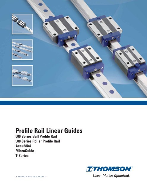
<strong>Profile</strong> <strong>Rail</strong> <strong>Linear</strong> <strong>Guides</strong><br />
500 Series Ball <strong>Profile</strong> <strong>Rail</strong><br />
500 Series Roller <strong>Profile</strong> <strong>Rail</strong><br />
AccuMini<br />
MicroGuide<br />
T-Series<br />
A DANAHER MOTION COMPANY<br />
<strong>Linear</strong> Motion. Optimized.
Thomson -<br />
<strong>Linear</strong> Motion. Optimized.<br />
<strong>Linear</strong> Motion. Optimized.<br />
Often the ideal design solution is not about finding the fastest, sturdiest, most accurate or even the least expensive option.<br />
Rather, the ideal solution is the optimal balance of performance, life and cost.<br />
Thomson is best positioned to help you most quickly configure the optimal linear motion solution for your application.<br />
• Thomson invented anti-friction linear bearing technology. We own the broadest standard product offering of mechanical<br />
motion technologies in the industry.<br />
• Modified versions of standard product are routine. White sheet design solutions available across our entire portfolio.<br />
• Choose Thomson and gain access to over 70 years of global application experience in diverse industries including<br />
packaging, factory automation, material handling, medical, clean energy, printing, automotive, machine tool, aerospace<br />
and defense.<br />
• As part of Danaher Motion, we are financially strong and unique in our ability to bring together control, drive, motor,<br />
power transmission and precision linear motion technologies.<br />
Thomson is the name you can trust for quality, innovation, on-time delivery, controlled costs, and<br />
reduced risk.<br />
In addition to the information contained in this document, a wealth of product and application information is available online<br />
at www.thomsonlinear.com. Also online are downloadable 3D models, software tools, our distributor locator and global<br />
contact information for Thomson. For immediate assistance in North America contact us at 1-540-633-3549 or email us at<br />
Thomson@danahermotion.com.<br />
Talk to us early in the design process to see how Thomson can help identify the optimal balance of performance, life and<br />
cost for your next application. And, call us or any of our 2000+ distribution partners around the world for fast delivery of<br />
replacement parts.<br />
The Danaher Business System -<br />
Building sustainable competitive advantage into your business<br />
The Danaher Business System (DBS) was established to increase the value we bring to customers. It is a mature and successful<br />
set of tools we use daily to continually improve manufacturing operations and product development processes. DBS is based<br />
on the principles of Kaizen which continuously and aggressively eliminate waste in every aspect of our business. DBS<br />
focuses the entire organization on achieving breakthrough results that create competitive advantages in quality, delivery and<br />
performance – advantages that are passed on to you. Through these advantages Thomson is able to provide you faster times<br />
to market as well as unsurpassed product selection, service, reliability and productivity.<br />
Local Support Around the Globe<br />
Application Centers Global Manufacturing Operations Global Design & Engineering Centers<br />
Application Centers<br />
Global Manufacturing Operations<br />
Global Design & Engineering Centers
An Overview of Danaher Motion – Thomson <strong>Profile</strong> <strong>Rail</strong><br />
<strong>Profile</strong> <strong>Rail</strong> <strong>Linear</strong> <strong>Guides</strong><br />
500 Series Ball<br />
<strong>Profile</strong> <strong>Rail</strong><br />
Overview ...................................................................................................................... 4<br />
500 Series Ball <strong>Profile</strong> <strong>Rail</strong> <strong>Linear</strong> Guide .............................................................. 8<br />
Thomson Next Generation <strong>Profile</strong> <strong>Rail</strong>. Superior Design. Superior Quality.<br />
Product overview ................................................................................................. 9<br />
Part numbering ................................................................................................... 19<br />
Datasheets .......................................................................................................... 21<br />
Options and accessories .................................................................................. 31<br />
Accuracy information ....................................................................................... 42<br />
Preload information ........................................................................................... 42<br />
500 Series Roller <strong>Profile</strong> <strong>Rail</strong> <strong>Linear</strong> Guide ........................................................ 44<br />
Thomson Next Generation <strong>Profile</strong> <strong>Rail</strong>. Superior Design. Superior Quality.<br />
Product overview ............................................................................................... 45<br />
Part numbering ................................................................................................... 53<br />
Datasheets .......................................................................................................... 55<br />
Options and accessories .................................................................................. 59<br />
Lubrication Fittings ............................................................................................ 70<br />
Accuracy information ....................................................................................... 71<br />
Preload information ........................................................................................... 71<br />
AccuMini.................................................................................................................... 73<br />
Ultra Compact, High Roll & Superior, Patented Ball Control Design.<br />
Product overview ............................................................................................... 73<br />
Part numbering ................................................................................................... 73<br />
Datasheets .......................................................................................................... 74<br />
Accuracy information ....................................................................................... 76<br />
Preload information ........................................................................................... 76<br />
MicroGuide ................................................................................................................ 77<br />
T-Series ....................................................................................................................... 84<br />
Installation Guide ..................................................................................................... 92<br />
Engineering Guide .................................................................................................... 96<br />
Sizing, selection and life load calculations ................................................... 97<br />
Deflection .......................................................................................................... 104<br />
Lubrication ........................................................................................................ 126<br />
Bellow cover calculations ............................................................................. 128<br />
Butt joint specification sheets ....................................................................... 129<br />
Conversion factors .......................................................................................... 132<br />
Interchange Guide .................................................................................................. 134<br />
For more information, or to place an order, please contact your local authorized<br />
Thomson distributor or Danaher Motion at 1-540-633-3400, Fax: 1-540-633-4162,<br />
or E-mail at profilerail@danahermotion.com.<br />
500 Series Roller<br />
<strong>Profile</strong> <strong>Rail</strong> AccuMini<br />
MicroGuide T-Series<br />
Lubrication<br />
Fittings<br />
Installation<br />
Guide<br />
Engineering<br />
Guide<br />
DANAHER MOTION is a registered trademark of Danaher Corporation. Danaher Motion makes every attempt to ensure accuracy and reliability of the specifications in this publication. Specifications are subject to change without notice.<br />
Danaher Motion provides this information „AS IS“ and disclaims all warranties, express or implied, including, but not limited to, implied warranties of merchantability and fitness for a particular purpose.It is the responsibility of the product user<br />
to determine the suitability of this product for a specific application. ©2004 Danaher Motion.<br />
www.thomsonlinear.com 3<br />
Interchange<br />
Guide
<strong>Linear</strong> Motion. Optimized.<br />
Overview of Danaher Motion – Thomson <strong>Profile</strong> <strong>Rail</strong> <strong>Linear</strong> <strong>Guides</strong><br />
Since the invention of the linear anti-friction Ball Bushing<br />
bearing by Thomson over 50 years ago, the Thomson<br />
precision linear products have meant high quality,<br />
innovative products. Today, Danaher Motion continues<br />
producing and developing these high quality, innovative<br />
products. The Danaher Motion Thomson <strong>Profile</strong> <strong>Rail</strong><br />
assortment consists of the Next Generation <strong>Profile</strong><br />
<strong>Rail</strong> “500 Series” Ball and Roller <strong>Linear</strong> <strong>Guides</strong>, compact<br />
miniature “MicroGuide,“ lightweight “T-Series,”<br />
and AccuMini.<br />
The Danaher Motion <strong>Profile</strong> <strong>Rail</strong> – <strong>Linear</strong> Guide Assortment<br />
is a complete assortment of rails and carriages in a<br />
broad range of styles, sizes and unique features<br />
produced to industry standard dimensions for<br />
easy retrofitting into existing applications or designing<br />
into new applications.<br />
500 Series Ball <strong>Profile</strong> <strong>Rail</strong> <strong>Linear</strong> Guide<br />
Features & Benefits<br />
Superior Design. Superior Quality.<br />
• Straight rails through advanced<br />
grinding technologies<br />
• Simple installation and greater accuracy<br />
with joint-free rails up to 6 meters<br />
• Smooth, quiet movement through patented insert<br />
molded recirculation paths and optimized geometries<br />
• Extended lubrication life as a result of grease<br />
pockets built into the recirculation path<br />
• Multiple carriage styles and sizes available<br />
• On site field modifiable modular seals<br />
• <strong>Rail</strong> and carriage options from stock or short delivery<br />
• Customization with expanded accessory offering<br />
• Replaces AccuGlide<br />
Typical Applications<br />
• Industrial Automation<br />
• Machine Tool Equipment<br />
• Material Handling<br />
• Precision Measuring Equipment<br />
• Industrial Robots<br />
• Food Processing Equipment<br />
4<br />
www.thomsonlinear.com
<strong>Profile</strong> <strong>Rail</strong> <strong>Linear</strong> <strong>Guides</strong><br />
500 Series Ball<br />
<strong>Profile</strong> <strong>Rail</strong><br />
500 Series Roller <strong>Profile</strong> <strong>Rail</strong> <strong>Linear</strong> Guide<br />
Features & Benefits<br />
Superior Design. Superior Quality.<br />
• Industry leading load capacities<br />
• High rigidity from back to back four roller track arrangement<br />
• Straight rails through advanced grinding technologies<br />
• Simple installation and greater accuracy with jointfree<br />
rails up to 6 meters<br />
• Smooth, quiet movement through patented insert<br />
molded recirculation paths and optimized geometries<br />
• Multiple carriage styles and sizes available<br />
• On site field modifiable modular seals<br />
• <strong>Rail</strong> and carriage options from stock or short delivery<br />
• Customization with expanded accessory offering<br />
• Replaces Accumax<br />
Typical Applications<br />
• Industrial Automation<br />
• Material Handling<br />
• Industrial Robots<br />
• Machine Tool Equipment<br />
• Precision Measuring Equipment<br />
• Food Processing Equipment<br />
AccuMini<br />
Features & Benefits<br />
• Ball control design for smooth, quiet, low friction<br />
at high speeds<br />
• Full length integral wiper which protects important<br />
bearing from contaminants… effective system life<br />
is maximized<br />
• Gothic design, which provides high roll moment<br />
capacity...a requirement for stand-alone applications<br />
• Wear-resistant, engineered polymer retainer which<br />
reduces system inertia and noise<br />
Typical Applications<br />
• Wafer Handling Equipment<br />
• Assembly Equipment<br />
• Inspection and Measurement Equipment<br />
www.thomsonlinear.com 5
<strong>Linear</strong> Motion. Optimized.<br />
MicroGuide<br />
Features & Benefits<br />
• Industry standard drop-in replacement<br />
• 440 stainless steel construction (corrosion resistance,<br />
little or no lubrication)<br />
• High precision accuracy (up to ±0.010mm)<br />
• Extremely smooth, quiet operation<br />
• Unlimited stroke<br />
• Low <strong>Profile</strong><br />
• High Moment Load Capacity for single rail / carriage<br />
applications<br />
• Whisper quiet movement<br />
• Gothic arch ball groove geometry provides enables<br />
single rail application<br />
• Sizes: 5mm, 7mm, 9mm, 12mm, 15mm (MicroGuide<br />
standard)<br />
• Sizes: 7mm, 9mm, 12mm, 15mm (MicroGuide wide)<br />
• Technical engineering support from Danaher Motion<br />
• One-piece length up to 1 meter (in sizes 7mm - 15mm)<br />
• Contact Danaher Motion for custom lengths and<br />
configurations<br />
Typical Applications<br />
• Front end semiconductor processing equipment<br />
• Backend semiconductor packaging and handling<br />
equipment<br />
• Medical diagnostic and imaging equipment<br />
• Laboratory automation equipment<br />
• Testing and inspection equipment<br />
T-Series<br />
Features & Benefits<br />
• Lightweight, flexible and forgiving alternative to all-steel<br />
profile rail.<br />
• High quality product made from aircraft aluminum alloy<br />
with hardened steel load bearing plates and ball paths.<br />
• Ideal choice for applications requiring reduced weight<br />
inertia.<br />
• High flexibility translates into N class radial run out only.<br />
• Proprietary "U" channel construction allows the rail to<br />
"flex" to accommodate poor machine bases or<br />
misalignment errors.<br />
• Lower cost installation and reduced installation time by<br />
eliminating the need for a costly machined base and<br />
special tools.<br />
• Drop-in replacement for conventional all-steel profile<br />
linear guides.<br />
Typical Applications<br />
• Airplanes<br />
• Automobiles<br />
• Machine Tool<br />
• Ships<br />
• Packaging<br />
6<br />
www.thomsonlinear.com
Assortment<br />
<strong>Profile</strong> <strong>Rail</strong> <strong>Linear</strong> <strong>Guides</strong><br />
500 Series Ball<br />
<strong>Profile</strong> <strong>Rail</strong><br />
SIZE MM<br />
500 Series Ball 500 Series Roller AccuMini MicroGuide T-Series<br />
Standard Narrow Standard Narrow Standard Standard Wide Standard<br />
––– Long Long Long Short Long Long<br />
––– ––– ––– ––– High High ––– ––– ––– ––– ––– ––– ––– ––– ––– –––<br />
5 •<br />
7 • •<br />
9 • •<br />
10 •<br />
12 • •<br />
15 • • • • • • •<br />
20 • • • • • • • • • •<br />
25 • • • • • • • • • • • • • •<br />
30 • • • • • •<br />
35 • • • • • • • • • • • • • •<br />
45 • • • • • • • •<br />
55 • • • •<br />
65 • • • •<br />
Style A B C D E F G A B C D A N/A N/A A G E F<br />
Page 21 21 23 23 25 25 27 55 55 57 57 75 78 80 87 87 89 89<br />
Application Criteria<br />
Feature 500 Series Ball 500 Series Roller AccuMini MicroGuide T-Series<br />
Load Capacity ••• •••• •• • ••<br />
Equivalent Loads all directions ••• •••• •• •• •<br />
Ultra Compactness • • ••• •••• •<br />
High Travel Accuracy •••• •••• •••• •••• •••<br />
Rigidity ••• •••• •• •• •<br />
Smoothness ••• •• •••• •••• •••<br />
Friction Characteristic •••• •• •••• •••• ••<br />
Admissable Speed •••• ••• •••• •••• •••<br />
Ease of Installation ••• •• •• ••• ••••<br />
Lightweight • • •• ••• ••••<br />
Industry Standard Dimensions •••• •••• •••• ••••<br />
Page 8 44 73 77 84<br />
• = satisfactory •••• = excellent<br />
www.thomsonlinear.com 7
<strong>Linear</strong> Motion. Optimized.<br />
<strong>Profile</strong> <strong>Rail</strong> <strong>Linear</strong> <strong>Guides</strong><br />
500 Series Ball <strong>Profile</strong> <strong>Rail</strong> <strong>Linear</strong> Guide<br />
High load capacities<br />
in all directions<br />
Industry standard dimensions<br />
Patented insert molded<br />
recirculation path with grease<br />
pockets resulting in quiet,<br />
low noise operation<br />
Multiple carriage designs,<br />
accuracies and preloads available<br />
Multiple rail accuracies<br />
Optimized ball path geometries and<br />
transitions for quiet, smooth operation<br />
One piece rail length up to 6 meters<br />
(size 25 and up)<br />
Multiple rail mounting hole plug options,<br />
or rails that mount up from underneath<br />
are available<br />
Both sides of rail are reference edges<br />
Six-runner block attachment bolts<br />
per carriage for superior system<br />
rigidity<br />
Universal mounting holes–runner blocks can be<br />
attached from top or bottom<br />
Multiple lubrication inlet points, easy<br />
field modification<br />
Superior rail straightness as a result<br />
of advanced grinding and straightening<br />
technology<br />
Modular accessories for on site<br />
upgrade without having to<br />
remove the carriage from the rail<br />
Corrosion resistance with Duralloy ®<br />
Thin Dense Chrome plating optional<br />
Low drag longitudinal seals standard for<br />
added protection along rail surface<br />
Removable double lip seal<br />
or low drag seal<br />
Extended standard dowel hole<br />
options for rails and carriages<br />
Complete interchangeability<br />
between rails and carriages<br />
Two point ball contact resulting<br />
in low friction<br />
High rigidity from optimized<br />
trapezoidal profile, allows for<br />
single carriage application<br />
Speeds up to 5 m/s<br />
Accelerations up to 100 m/s 2<br />
8<br />
www.thomsonlinear.com
500 Series Ball <strong>Profile</strong> <strong>Rail</strong> <strong>Linear</strong> Guide<br />
<strong>Profile</strong> <strong>Rail</strong> <strong>Linear</strong> <strong>Guides</strong><br />
500 Series Ball<br />
<strong>Profile</strong> <strong>Rail</strong><br />
Features<br />
The Thomson 500 Series Ball <strong>Linear</strong> Guide provides long life,<br />
exceptional rigidity, high dynamic and static load capa cities,<br />
accommodation for high moment loads, high running<br />
accuracy, multiple sealing options and multiple lubrication<br />
inlet options. This allows for on-site field modifications, and<br />
interchangeability with competitor offering.<br />
These properties result in improved machine accuracies and<br />
rigidity resulting in reduced vibration extending machine and<br />
tool life. This has a direct effect on operational efficiency<br />
resulting in cost savings for the user.<br />
Available in 7 carriage designs, and sizes 15 to 45mm.<br />
Materials <strong>Linear</strong> <strong>Guides</strong><br />
The 500 Series Ball <strong>Linear</strong> <strong>Guides</strong> are produced from high<br />
quality bearing steel. All carriages and rolling elements are<br />
through hardened and all rails are case hardened (except<br />
size 15 rail which is through hardened). The end cap is<br />
constructed of a high strength, glass filled nylon with nitrile<br />
rubber seal. Stringent quality controls are in place to ensure<br />
consistency of materials from the source, allowing us to<br />
ensure that we delivery the highest quality product.<br />
Interchangeability<br />
The 500 Series Ball <strong>Linear</strong> <strong>Guides</strong> are completely<br />
interchangeable. Any carriage can be run on any rail of the<br />
same accuracy without compromising system accuracy.<br />
This is the result of our stringent manufacturing process<br />
controls.<br />
Accuracy and Preload<br />
The 500 Series Ball <strong>Linear</strong> <strong>Guides</strong> are available in three<br />
different accuracy classes, three different preload ranges<br />
and with clearance to allow for customization to your<br />
appli cation needs.<br />
Straightness<br />
The 500 Series Ball rail is subjected to multiple straightening<br />
processes during and after grinding of the roller paths.<br />
These added processes and inspections result in some of<br />
the straightest rails in the market today, improving machine<br />
accuracies wherever the 500 Series Ball is used.<br />
Rigidity<br />
The 500 Series Ball <strong>Linear</strong> Guide rail utilizes a special<br />
trapezoidal profile that maximizes the carriage cross<br />
section, resulting in the highest possible rigidity.<br />
www.thomsonlinear.com 9
<strong>Linear</strong> Motion. Optimized.<br />
<strong>Profile</strong> <strong>Rail</strong> <strong>Linear</strong> <strong>Guides</strong><br />
500 Series Ball <strong>Profile</strong> <strong>Rail</strong> <strong>Linear</strong> Guide<br />
Running Smoothness / Low Noise<br />
The running smoothness and low noise are the result of<br />
a patented, custom insert molded recirculation path that has<br />
an optimized geometric shape and minimal transitions, to<br />
ensure smooth and quiet operation in both low and high-speed<br />
operation.<br />
In addition, the balls make contact at only two points<br />
between rail and carriage. As a result, friction is reduced to<br />
a minimum, resulting in quiet, smooth operation.<br />
Back-to-Back<br />
The 500 Series <strong>Linear</strong> Guide utilizes a back-to-back bearing<br />
arrangement, resulting in added rigidity. As a result, the 500<br />
Series Ball can be used in single rail applications.<br />
Internal Grease Pockets<br />
The patented insert molded recirculation path has built in<br />
grease pockets. These provide an extra level of security by<br />
ensuring adequate lubrication is available to the ball bearings<br />
to help extend life.<br />
The pocket and area between the balls provide greater grease<br />
quantities in the ball path than a conventional<br />
designed linear guide bearing.<br />
Multiple Lubrication Options<br />
The standard end cap is designed for flexibility. The end cap<br />
comes standard with four lubrication inlet options. These<br />
inlet options are easily changed on-site in the field or can be<br />
supplied from the factory.<br />
Unsure of the best lubrication inlet location? These carriages<br />
allow the user to make these changes easily in the field to<br />
optimize the system performance. In addition, they allow for<br />
ease in maintenance – all without removing the carriage from<br />
the rail.<br />
10<br />
www.thomsonlinear.com
500 Series Ball <strong>Profile</strong> <strong>Rail</strong> <strong>Linear</strong> Guide<br />
<strong>Profile</strong> <strong>Rail</strong> <strong>Linear</strong> <strong>Guides</strong><br />
500 Series Ball<br />
<strong>Profile</strong> <strong>Rail</strong><br />
Modular Accessory Options<br />
The standard carriage is supplied with low friction<br />
double lip seals and longitudinal seals that completely<br />
encase the bearing carriage to protect the balls and track<br />
surfaces and minimize lubrication loss.<br />
Optional metal scrapers or wipers, lube blocks and oil<br />
reservoir components can be easily added on-site in the<br />
field or can be supplied assembled from the factory.<br />
The trapezoidal rail profile allows for easy servicing and<br />
replacing or adding of the end cap, additional wiper and<br />
oil reservoir without removing the carriage from the<br />
rail.<br />
These innovative design features allow users to easily,<br />
efficiently, and economically upgrade carriage sealing.<br />
Longitudinal Seals<br />
The carriage has built-in under carriage low drag longitudinal<br />
seals that protect the balls and ball path from<br />
contamination. These longitudinal seals are an added<br />
protection to increase the life and overall performance.<br />
Extended Standards<br />
Extended Standards are an assortment of Danaher Motion<br />
dowel hole options for both carriage and rail products.<br />
Take the guesswork out of design by using our standard<br />
assortment of dowel hole options for ease of design and<br />
availability, another solution from Danaher Motion. Refer<br />
to page 29, 30 and 33 for more information and detailed<br />
datasheets.<br />
<strong>Rail</strong> Accessories<br />
The rails have multiple options to protect the mounting<br />
holes to eliminate possible contamination entry into the<br />
bearing. Custom designed plastic plugs, mylar tape and<br />
stainless steel rail cover strip are available.<br />
Retained Balls<br />
The rolling elements of the carriages are retained within<br />
the bearing so the carriage can be removed from the rail<br />
without worrying about the balls falling out. It is recommended<br />
to place any removed carriage onto an assembly<br />
rail or shipping arbor to provide added protection to the<br />
rolling elements.<br />
www.thomsonlinear.com 11
<strong>Linear</strong> Motion. Optimized.<br />
500 Series <strong>Profile</strong> <strong>Rail</strong> Enhanced Carriage<br />
New, 66% Smoother Running Design, with 50%<br />
Lower Drag Force *<br />
New Ball Spacer and Stainless Steel Options<br />
Features and Benefits<br />
Now available in all sizes: the new Thomson 500 Series<br />
<strong>Profile</strong> <strong>Rail</strong> enhanced carriage design can improve the<br />
smoothness and precision of your linear motion application.<br />
New optional 440B stainless carriages and rails provide<br />
corrosion resistance well-suited for medical, food, electronic<br />
assembly and semiconductor applications.<br />
• New ball spacer carriage option provides smooth, quiet<br />
motion.<br />
• New, smoother running design optimizes the surface<br />
interfaces between steel and plastic transition areas along<br />
the ball bearing circulation path.<br />
• New standard end seals provide twice the contaminant<br />
protection compared to competitive products. Optional low<br />
drag end seals are ideal for low push force requirements.<br />
• Four longitudinal seals per carriage provide much better<br />
contaminant protection than competitive designs with<br />
only two longitudinal seals.<br />
• Additional lubrication reservoir enables longer running<br />
time and easy change end caps & seals are quick to<br />
replace.<br />
• 100% interchangeable with previous Thomson 500 Series<br />
carriage and rail.<br />
* 66% smoothness increase measured as variability of drag force while the<br />
carriage is in motion. 50% lower drag force measured with new low drag<br />
seals option; 41% lower drag force measured with standard wiper option.<br />
12<br />
www.thomsonlinear.com
500 Series Ball <strong>Profile</strong> <strong>Rail</strong> <strong>Linear</strong> Guide<br />
<strong>Profile</strong> <strong>Rail</strong> <strong>Linear</strong> <strong>Guides</strong><br />
500 Series Ball<br />
<strong>Profile</strong> <strong>Rail</strong><br />
Modular Accessory Exploded View<br />
Standard end cap<br />
(531 EC)<br />
Integral double lip seal<br />
Standard end cap*<br />
(531 EC)<br />
Recirculation path<br />
Oil reservoir*<br />
(531 OW)<br />
Balls<br />
Additional wiper*<br />
(531 WR or VR)<br />
Metal scraper<br />
(531 ZZ)<br />
Plastic plugs<br />
(531 HP)<br />
<strong>Rail</strong><br />
(521)<br />
Grease fitting<br />
Attaching bolts<br />
Also available (not shown):<br />
• Lube Block (531 LL)<br />
• Mylar <strong>Rail</strong> Tape (531 RT)<br />
• Bolt up from bottom rail (521 Type U)<br />
• Stainless Steel <strong>Rail</strong>, Cover Strip and <strong>Rail</strong> (521 Type C<br />
and 531RCS)<br />
* Can be installed without removing carriage from the<br />
rail<br />
The modular building block design of the 500 Series Ball<br />
<strong>Profile</strong> <strong>Rail</strong> <strong>Linear</strong> Guide assembly allows for easy on-site<br />
field upgrades for quick seal or lubrication changes, all<br />
without the need to remove the carriage from the rail.<br />
www.thomsonlinear.com 13
www.thomsonlinear.com<br />
14<br />
<strong>Linear</strong> Motion. Optimized.<br />
500 Series Ball Standard Carriages<br />
15<br />
20<br />
25<br />
30<br />
35<br />
45<br />
20<br />
25<br />
30<br />
35<br />
45<br />
15<br />
20<br />
25<br />
30<br />
35<br />
20<br />
25<br />
30<br />
35<br />
1500<br />
3000<br />
6000<br />
6000<br />
6000<br />
6000<br />
3000<br />
6000<br />
6000<br />
6000<br />
6000<br />
1500<br />
3000<br />
6000<br />
6000<br />
6000<br />
3000<br />
6000<br />
6000<br />
6000<br />
511H15A0<br />
-<br />
-<br />
511H20A0<br />
-<br />
-<br />
511H25A0<br />
-<br />
-<br />
511H30A0<br />
-<br />
-<br />
511H35A0<br />
-<br />
-<br />
511H45A0<br />
-<br />
-<br />
511H20B0<br />
-<br />
-<br />
511H25B0<br />
-<br />
-<br />
511H30B0<br />
-<br />
-<br />
511H35B0<br />
-<br />
-<br />
511H45B0<br />
-<br />
-<br />
511H15C0<br />
-<br />
-<br />
511H20C0<br />
-<br />
-<br />
511H25C0<br />
-<br />
-<br />
511H30C0<br />
-<br />
-<br />
511H35C0<br />
-<br />
-<br />
511H20D0<br />
-<br />
-<br />
511H25D0<br />
-<br />
-<br />
511H30D0<br />
-<br />
-<br />
511H35D0<br />
-<br />
-<br />
H<br />
P<br />
U<br />
H<br />
P<br />
U<br />
H<br />
P<br />
U<br />
H<br />
P<br />
U<br />
H<br />
P<br />
U<br />
H<br />
P<br />
U<br />
H<br />
P<br />
U<br />
H<br />
P<br />
U<br />
H<br />
P<br />
U<br />
H<br />
P<br />
U<br />
H<br />
P<br />
U<br />
H<br />
P<br />
U<br />
H<br />
P<br />
U<br />
H<br />
P<br />
U<br />
H<br />
P<br />
U<br />
H<br />
P<br />
U<br />
H<br />
P<br />
U<br />
H<br />
P<br />
U<br />
H<br />
P<br />
U<br />
H<br />
P<br />
U<br />
511H15A1<br />
511P15A1<br />
511U15A1<br />
511H20A1<br />
511P20A1<br />
511U20A1<br />
511H25A1<br />
511P25A1<br />
511U25A1<br />
511H30A1<br />
511P30A1<br />
511U30A1<br />
511H35A1<br />
511P35A1<br />
511U35A1<br />
511H45A1<br />
511P45A1<br />
511U45A1<br />
511H20B1<br />
511P20B1<br />
511U20B1<br />
511H25B1<br />
511P25B1<br />
511U25B1<br />
511H30B1<br />
511P30B1<br />
511U30B1<br />
511H35B1<br />
511P35B1<br />
511U35B1<br />
511H45B1<br />
511P45B1<br />
511U45B1<br />
511H15C1<br />
511P15C1<br />
511U15C1<br />
511H20C1<br />
511P20C1<br />
511U20C1<br />
511H25C1<br />
511P25C1<br />
511U25C1<br />
511H30C1<br />
511P30C1<br />
511U30C1<br />
511H35C1<br />
511P35C1<br />
511U35C1<br />
511H20D1<br />
511P20D1<br />
511U20D1<br />
511H25D1<br />
511P25D1<br />
511U25D1<br />
511H30D1<br />
511P30D1<br />
511U30D1<br />
511H35D1<br />
511P35D1<br />
511U35D1<br />
511H15A2<br />
511P15A2<br />
511U15A2<br />
511H20A2<br />
511P20A2<br />
511U20A2<br />
511H25A2<br />
511P25A2<br />
511U25A2<br />
511H30A2<br />
511P30A2<br />
511U30A2<br />
511H35A2<br />
511P35A2<br />
511U35A2<br />
511H45A2<br />
511P45A2<br />
511U45A2<br />
511H20B2<br />
511P20B2<br />
511U20B2<br />
511H25B2<br />
511P25B2<br />
511U25B2<br />
511H30B2<br />
511P30B2<br />
511U30B2<br />
511H35B2<br />
511P35B2<br />
511U35B2<br />
511H45B2<br />
511P45B2<br />
511U45B2<br />
511H15C2<br />
511P15C2<br />
511U15C2<br />
511H20C2<br />
511P20C2<br />
511U20C2<br />
511H25C2<br />
511P25C2<br />
511U25C2<br />
511H30C2<br />
511P30C2<br />
511U30C2<br />
511H35C2<br />
511P35C2<br />
511U35C2<br />
511H20C2<br />
511P20D2<br />
511U20D2<br />
511H25D2<br />
511P25D2<br />
511U25D2<br />
511H30D2<br />
511P30D2<br />
511U30D2<br />
511H35D2<br />
511P35D2<br />
511U35D2<br />
-<br />
511P15A3<br />
511U15A3<br />
-<br />
511P20A3<br />
511U20A3<br />
-<br />
511P25A3<br />
511U25A3<br />
-<br />
511P30A3<br />
511U30A3<br />
-<br />
511P35A3<br />
511U35A3<br />
-<br />
511P45A3<br />
511U45A3<br />
-<br />
511P20B3<br />
511U20B3<br />
-<br />
511P25B3<br />
511U25B3<br />
-<br />
511P30B3<br />
511U30B3<br />
-<br />
511P35B3<br />
511U35B3<br />
-<br />
511P45B3<br />
511U45B3<br />
-<br />
511P15C3<br />
511U15C3<br />
-<br />
511P20C3<br />
511U20C3<br />
-<br />
511P25C3<br />
511U25C3<br />
-<br />
511P30C3<br />
511U30C3<br />
-<br />
511P35C3<br />
511U35C3<br />
-<br />
511P20D3<br />
511U20D3<br />
-<br />
511P25D3<br />
511U25D3<br />
-<br />
511P30D3<br />
511U30D3<br />
-<br />
511P35D3<br />
511U35D3<br />
521H15A<br />
521P15A<br />
521U15A<br />
521H20A<br />
521P20A<br />
521U20A<br />
521H25A<br />
521P25A<br />
521U25A<br />
521H30A<br />
521P30A<br />
521U30A<br />
521H35A<br />
521P35A<br />
521U35A<br />
521H45A<br />
521P45A<br />
521U45A<br />
521H20A<br />
521P20A<br />
521U20A<br />
521H25A<br />
521P25A<br />
521U25A<br />
521H30A<br />
521P30A<br />
521U30A<br />
521H35A<br />
521P35A<br />
521U35A<br />
521H45A<br />
521P45A<br />
521U45A<br />
521H15A<br />
521P15A<br />
521U15A<br />
521H20A<br />
521P20A<br />
521U20A<br />
521H25A<br />
521P25A<br />
521U25A<br />
521H30A<br />
521P30A<br />
521U30A<br />
521H35A<br />
521P35A<br />
521U35A<br />
521H20A<br />
521P20A<br />
521U20A<br />
521H25A<br />
521P25A<br />
521U25A<br />
521H30A<br />
521P30A<br />
521U30A<br />
521H35A<br />
521P35A<br />
521U35A<br />
Size<br />
Style<br />
Standard<br />
Carriage<br />
A<br />
B<br />
C<br />
Narrow<br />
Long<br />
Carriage<br />
Narrow<br />
Carriage<br />
Standard<br />
Long<br />
Carriage<br />
D<br />
Accuracy Clearance 0.03C 0.08C<br />
Preload<br />
Basic Part Number<br />
0.13C<br />
Appropriate <strong>Rail</strong><br />
Standard Style<br />
Max. Single Piece<br />
<strong>Rail</strong> Length (mm)<br />
Danaher Motion offers six carriage styles with six mounting<br />
holes allowing for additional mounting configurations in<br />
the field or for retrofitting. All provide superior rigidity and<br />
design flexibility.
<strong>Profile</strong> <strong>Rail</strong> <strong>Linear</strong> <strong>Guides</strong><br />
500 Series Ball<br />
<strong>Profile</strong> <strong>Rail</strong><br />
Narrow<br />
High<br />
Carriage<br />
Narrow<br />
High<br />
Long<br />
Carriage<br />
Narrow<br />
Short<br />
Carriage<br />
Style<br />
E<br />
F<br />
G<br />
Size<br />
15<br />
25<br />
30<br />
35<br />
45<br />
25<br />
30<br />
35<br />
45<br />
15<br />
20<br />
Basic Part Number<br />
Accuracy Preload<br />
Clearance 0.03C 0.08C<br />
H<br />
P<br />
U<br />
H<br />
P<br />
U<br />
H<br />
P<br />
U<br />
H<br />
P<br />
U<br />
H<br />
P<br />
U<br />
H<br />
P<br />
U<br />
H<br />
P<br />
U<br />
H<br />
P<br />
U<br />
H<br />
P<br />
U<br />
H<br />
P<br />
U<br />
H<br />
P<br />
U<br />
511H15E0<br />
-<br />
-<br />
511H25E0<br />
-<br />
-<br />
511H30E0<br />
-<br />
-<br />
511H35E0<br />
-<br />
-<br />
511H45E0<br />
-<br />
-<br />
511H25F0<br />
-<br />
-<br />
511H30F0<br />
-<br />
-<br />
511H35F0<br />
-<br />
-<br />
511H45F0<br />
-<br />
-<br />
511H15G0<br />
-<br />
-<br />
511H20G0<br />
-<br />
-<br />
511H15E1<br />
511P15E1<br />
511U15E1<br />
511H25E1<br />
511P25E1<br />
511U25E1<br />
511H30E1<br />
511P30E1<br />
511U30E1<br />
511H35E1<br />
511P35E1<br />
511U35E1<br />
511H45E1<br />
511P45E1<br />
511U45E1<br />
511H25F1<br />
511P25F1<br />
511U25F1<br />
511H23F1<br />
511P30F1<br />
511U30F1<br />
511H35F1<br />
511P35F1<br />
511U35F1<br />
511H45F1<br />
511P45F1<br />
511U45F1<br />
511H15G1<br />
511P15G1<br />
511U15G1<br />
511H20G1<br />
511P20G1<br />
511U20G1<br />
511H15E2<br />
511P15E2<br />
511U15E2<br />
511H25E2<br />
511P25E2<br />
511U25E2<br />
511H30E2<br />
511P30E2<br />
511U30E2<br />
511H35E2<br />
511P35E2<br />
511U35E2<br />
511H45E2<br />
511P45E2<br />
511U45E2<br />
511H25F2<br />
511P25F2<br />
511U25F2<br />
511H30F2<br />
511P30F2<br />
511U30F2<br />
511H35F2<br />
511P35F2<br />
511U35F2<br />
511H45F2<br />
511P45F2<br />
511U45F2<br />
511H15G2<br />
511P15G2<br />
511U15G2<br />
511H20G2<br />
511P20G2<br />
511U20G2<br />
0.13C<br />
-<br />
511P15E3<br />
511U15E3<br />
-<br />
511P25E3<br />
511U25E3<br />
-<br />
511P30E3<br />
511U30E3<br />
-<br />
511P35E3<br />
511U35E3<br />
-<br />
511P45E3<br />
511U45E3<br />
-<br />
511P20F3<br />
511U20F3<br />
-<br />
511P30F3<br />
511U30F3<br />
-<br />
511P35F3<br />
511U35F3<br />
-<br />
511P45F3<br />
511U45F3<br />
-<br />
511P15G3<br />
511U15G3<br />
-<br />
511P20G3<br />
511U20G3<br />
Appropriate <strong>Rail</strong><br />
Standard Style<br />
521H15A<br />
521P15A<br />
521U15A<br />
521H25A<br />
521P25A<br />
521U25A<br />
521H30A<br />
521P30A<br />
521U30A<br />
521H35A<br />
521P35A<br />
521U35A<br />
521H45A<br />
521P45A<br />
521U45A<br />
521H25A<br />
521P25A<br />
521U25A<br />
521H30A<br />
521P30A<br />
521U30A<br />
521H35A<br />
521P35A<br />
521U35A<br />
521H45A<br />
521P45A<br />
521U45A<br />
521H15A<br />
521P15A<br />
521U15A<br />
521H20A<br />
521P20A<br />
521U20A<br />
Max. Single Piece<br />
<strong>Rail</strong> Length (mm)<br />
1500<br />
6000<br />
6000<br />
6000<br />
6000<br />
6000<br />
6000<br />
6000<br />
6000<br />
1500<br />
3000<br />
Type A<br />
Type U<br />
Extended Standard Carriage Options<br />
The carriages are also available with the Thomson standard dowel holes or lubrication<br />
inlets as shown on pages 29 to 33 or special lubricants either from stock or with a short<br />
lead-time.<br />
<strong>Rail</strong> Types and Accessories<br />
The rails are available in two configurations:<br />
• Bolt down from the top – 521 Type A<br />
• Bolt up from the bottom – 521 Type U<br />
The standard 521 rail mounting holes can be plugged or sealed after installation with the<br />
options below.<br />
Plastic Plugs<br />
531HP plastic plugs are an inexpensive and simple method to seal the rail attachment<br />
bolt area. The plastic plugs are easily driven in place to any rail with a soft non-metallic<br />
drift. They can easily be removed.<br />
Mylar Tape<br />
A simple and low cost alternative is specialty Mylar tape that can be placed quickly on<br />
the top surface of the rail. Part number 531RT is available in 3 meter lengths.<br />
Stainless Steel Cover Strip<br />
Option 531RCS utilizes a special rail (521 Type C) and stainless steel cover strip that is<br />
easily installed with the proper mounting tool.<br />
www.thomsonlinear.com 15
<strong>Linear</strong> Motion. Optimized.<br />
Additional Seal Types and Lubrication Accessories<br />
The carriage is designed with modular sealing and<br />
lubrication options for simple on-site field modification<br />
or can be supplied factory direct.<br />
The standard carriage end cap has an integral low friction<br />
double lip seal and longitudinal seal that completely<br />
encase the bearing carriage. The double lip design<br />
keeps contaminants out and lubrication in. It also allows<br />
for grease to purge out of the carriage to prevent<br />
excessive lubrication, which can result in higher operating<br />
temperatures. This double lip design can be used with oil<br />
lubrication.<br />
The standard carriage end cap is equipped with a lubrication<br />
inlet centered with a specially designed lubricant<br />
channel to direct the lubrication to individual ball tracks.<br />
The lubrication inlet can be easily changed in the field<br />
or supplied from the factory with a side inlet or top inlet.<br />
Additional Seal<br />
The 531 WR and 531 VR seals provide an additional<br />
level of protection from contaminants to the assembly.<br />
These additional components can easily be added on-site<br />
without removing the carriage from the rail. They are<br />
supplied with the required screws to make the installation<br />
simple.<br />
• 531 WR is constructed from durable nitrile rubber (Buna N)<br />
• 531 VR is constructed from durable Viton ®<br />
These seals can be used in conjunction with other<br />
optional modular accessories providing an easy upgrade<br />
to the standard seal. These can be easily installed on-site<br />
in the field or can be supplied from the factory.<br />
Metal Scraper<br />
The Type 531 ZZ Metal Scraper made of stainless steel,<br />
serves as an added protection to the seal lips against<br />
large dirt particles, metal shavings or chips. Large<br />
contaminants are easily pushed away providing an extra<br />
level of protection to the seal lips. The Metal Scraper<br />
is easily installed in conjunction with the other optional<br />
modular accessories providing you with an easy upgrade<br />
to the standard seal. These can be easily installed on-site<br />
in the field or can be supplied from the factory.<br />
16<br />
www.thomsonlinear.com
<strong>Profile</strong> <strong>Rail</strong> <strong>Linear</strong> <strong>Guides</strong><br />
500 Series Ball<br />
<strong>Profile</strong> <strong>Rail</strong><br />
Oil Reservoir<br />
The Type 531 OW oil reservoir is a cost effective, automatic<br />
lubrication system. It is constructed with an integrated oil<br />
reservoir that provides a uniform, consistent lubricating<br />
oil to the ball paths for extended periods of time. The Type<br />
531 OW oil reservoir lubrication plate eliminates the need<br />
for a routine maintenance schedule, assures lubrication<br />
gets to the required points, can be refilled if required, and<br />
can operate up to 5000 km of travel. The Type 531 OW oil<br />
reservoir can be easily installed in conjunction with other<br />
optional modular accessories providing an easy upgrade<br />
to the standard seals. These can be easily installed<br />
on-site in the field or can be supplied from the factory.<br />
Lube Block<br />
The 531 LL Lube Block is a solid lubricant that is a mixture<br />
of polymers, oils and selected additives that reduce the<br />
penetration of dirt, grit, and liquids into the ball path, preventing<br />
premature failures. The oil diffuses, lubricating the<br />
ball path surfaces by capillary action. Additional oil is supplied<br />
to the ball path surfaces from the polymer. For additional<br />
protection the assembly is packed with EP2 grease. There<br />
is no need for maintenance or additional lubrication during<br />
the life of the Lube Block filled bearing. The 531 LL Lube<br />
Block can be easily installed in conjunction with the other<br />
optional modular accessories providing an easy upgrade<br />
to the standard seal. These can be easily installed on-site<br />
in the field or can be supplied from the factory.<br />
Relative Drag Comparison for Design Consideration<br />
Type<br />
Standard carriage<br />
Rubber Wiper (531 WR)<br />
Viton ® Wiper (531 VR)<br />
Metal Scraper (531 ZZ)<br />
Oil Reservoir (531 OW)<br />
Lube Block (531 LL)<br />
• Low<br />
Relative Drag<br />
•<br />
• • •<br />
• • •<br />
•<br />
• •<br />
• • • •<br />
For ordering information<br />
or for additional<br />
Seal Types and<br />
Lubrication Accessories,<br />
see pages 37 to 38.<br />
Bellows<br />
Standard bellows are available for all assemblies. The<br />
bellows cover the entire length of the rail. The bellows<br />
are used to provide additional protection against dirt, dust<br />
and splashed liquids. Installation is simple and requires<br />
little time. Retrofitting is possible when the rail ends are<br />
drilled for the attachment of the end plate 531. Bellows<br />
are available in three styles:<br />
• Type B “Low <strong>Profile</strong>” with outside dimensions that do<br />
not exceed the carriage<br />
• Type C “High Compression”<br />
• Type W “Walk On” capable of handling the harshest<br />
environments with a 90kg load bearing capacity<br />
The bellow can be easily installed in conjunction with<br />
other optional modular seals providing you with a simple<br />
upgrade to the standard seal. These can be installed<br />
on-site in the field or can be supplied from the factory.<br />
Note: Additional modular accessories add additional drag<br />
to the carriage assembly resulting in increased start up<br />
friction and power consumption.<br />
www.thomsonlinear.com 17
<strong>Linear</strong> Motion. Optimized.<br />
500 Series Ball Spacer<br />
500 Series Ball <strong>Profile</strong> <strong>Rail</strong> carriages are now available with<br />
ball spacer elements that significantly reduce the running<br />
noise of the carriage. The ball spacer carriage is available<br />
in sizes 20, 25, 30, 35 and 45. It is a drop-in replacement for<br />
the current ball carriage; all external carriage dimensions<br />
are exactly the same.<br />
The noise reduction is achieved by inserting plastic discs<br />
between each ball bearing. This reduces noise by preventing<br />
the balls from contacting each other as well as bumping<br />
into the ball track. The addition of the plastic discs requires<br />
a reduced number of load carrying balls, which leads to a<br />
slight reduction of the static and dynamic load capacity of<br />
the ball spacer carriage.<br />
Features and Benefits:<br />
• Significant noise reduction (-6 dB)<br />
• Minimum reduction of dynamic and static load capacity-<br />
Contact Danaher Motion Application Engineering for<br />
load rating details<br />
• Drop-in replacement for 511 ball carriage<br />
• Same accessory options as 511 ball carriage<br />
• Better or identical performance in comparison to<br />
competitor push force and noise<br />
• Carriage type designation: 513<br />
Noise Measurement, 35mm Carriage<br />
Old design<br />
Ball Spacer Technology Comparison<br />
Thomson Ball Spacer<br />
Enhanced design<br />
Enhanced design<br />
(with ball spacer)<br />
Competitor 1<br />
(without caged ball)<br />
Competitor 2<br />
(without caged ball)<br />
Competitor 2<br />
(with caged ball)<br />
62 64 66 68 70 72 74 76<br />
Noise, dB(A) at 1m/s<br />
Competitor Ball Chain<br />
Spacer<br />
Ball<br />
Ball Spacer Spacer Link<br />
Thomson 513 Ball Spacer<br />
Competitor Ball Chain<br />
Internal Forces No tensile load Tensile load on spacer links<br />
Quality Automatic inspection of each spacer element Optical inspection not possible without bending link<br />
Balltrack<br />
clearances<br />
Any clearance between balls and spacers is<br />
minimized during assembly<br />
Spacer link tolerances leads to undefined<br />
clearances<br />
Push Force Slight increase in push force Significant increase in push force<br />
Reliability Fewer elements = fewer failure modes Broken link elements can block re-circulation path<br />
18<br />
www.thomsonlinear.com
500 Series Ball<br />
<strong>Profile</strong> <strong>Rail</strong> <strong>Linear</strong> <strong>Guides</strong><br />
500 Series Ball<br />
<strong>Profile</strong> <strong>Rail</strong><br />
Part Numbering Description<br />
Ball Carriage<br />
STANDARD Standard<br />
OPTIONS<br />
5 1 1 H 15 A 1 D L W Z ES1 SM<br />
500 Series<br />
<strong>Profile</strong> Carriage<br />
Specials<br />
SM Special per customer print<br />
Product Type<br />
1 Carriage<br />
Type<br />
1 Ball<br />
3 Ball Spacer<br />
Accuracy Class 2<br />
H High Grade<br />
P Precision Grade<br />
U Ultra Precision Grade<br />
Carriage Style<br />
A Standard<br />
B Standard Long<br />
C Narrow<br />
D Narrow Long<br />
E Narrow High<br />
F Narrow Long High<br />
G Narrow Short<br />
4<br />
Size<br />
15 30<br />
20 35<br />
25 45<br />
Preload<br />
0 Clearance<br />
1 Approximately 0.03 C<br />
2 Approximately 0.08 C<br />
3 Approximately 0.13 C<br />
Extended Standards - Options<br />
ES1 6mm Dowel Hole - Slip Fit<br />
ES2 10mm Dowel Hole - Slip Fit<br />
ES3 1/4” Dowel Hole - Slip Fit<br />
ES4 3/8” Dowel Hole - Slip Fit<br />
ES10 Side lubrication in end caps<br />
ES11 Top lubrication in end caps<br />
ES12 (2) 6mm Dowel Holes - Press Fit<br />
ES13 (2) 10mm Dowel Holes - Press Fit<br />
ES14 (2) 1/4” Dowel Holes - Press Fit<br />
ES15 (2) 3/8” Dowel Holes - Press Fit<br />
G1 Greased with Mobilux ® EP2<br />
G2<br />
GS<br />
Corrosion-resistant Option<br />
®<br />
D Duralloy Thin Dense Chrome<br />
S Stainless Steel Material<br />
(available in sizes 15 and<br />
20 and carriage styles A and<br />
C only)<br />
Greased with Krytox ® GPL227<br />
Greased per customer<br />
specification<br />
Accessories 1<br />
L Long Life Lube Block<br />
N Additional Oil Reservoir<br />
W Additional Rubber Wiper<br />
V Additional Viton Wiper<br />
Z Metal Scraper<br />
C Bellow Clips<br />
K Low Drag Seal<br />
1. Accessory combination part numbers are listed from carriage end cap<br />
outward. Not all combinations are available. For specific combination<br />
availability see pages 35-36.<br />
3. New enhanced carriage does not retain ball bearings when end cap<br />
is removed. Removal of end caps can result in loss of ball bearings.<br />
4. Ball Spacer carriage not available in size 15.<br />
2. The 500 Series Ball lowest accuracy grade is High as a result of tight<br />
manufacturing controls and grinding capabilities. We do not offer<br />
Normal grade accuracy, our High grade is our Normal grade.<br />
www.thomsonlinear.com 19
<strong>Linear</strong> Motion. Optimized.<br />
500 Series Ball<br />
Part Numbering Description<br />
Ball <strong>Rail</strong><br />
Type<br />
1 Ball<br />
500 Series<br />
<strong>Profile</strong> <strong>Rail</strong><br />
Product Type<br />
2 <strong>Rail</strong><br />
STANDARD<br />
OPTIONS<br />
STANDARD<br />
5 2 1 H 15 A D DH1 SM +xxxx Y= (see note 1)<br />
Length (mm)<br />
xxxx Customer Specified Length<br />
RL1500 Stock Length 2<br />
Accuracy Class<br />
H High Grade<br />
P Precision Grade<br />
U Ultra Precision Grade<br />
<strong>Rail</strong> Style<br />
A Standard<br />
U Bolt up from Bottom<br />
C Cover Strip<br />
4<br />
15<br />
20<br />
25<br />
Size<br />
30<br />
35<br />
45<br />
Corrosion-resistant option<br />
D Duralloy ® (H and P accuracy only)<br />
5<br />
S Stainless Steel Material<br />
Machined Options<br />
DH1 6mm Dowel Hole + Slot<br />
DH2 10mm Dowel Hole + Slot<br />
DH3 1⁄4” Dowel Hole + Slot<br />
DH4 3⁄8” Dowel Hole + Slot<br />
JT 3 Butt Joint<br />
E Bellow Clips Attached<br />
Specials<br />
SM Special Per Customer Print<br />
1. Y = Distance from end of rail to center of first mounting hole,<br />
Y1 = Y2 unless specified<br />
2. Stock length rails are considered random length, total length may<br />
exceed specified length, and Y1/Y2 are not equal. To be used by<br />
customer who will cut to length.<br />
3. Customer drawing required at time of quote and order.<br />
See page 130 for more information and templates.<br />
4. Cover strip rail available in size 25 and up only.<br />
5. Available in sizes 15 and 20 only. Max. rail length at 1,000mm.<br />
Ball Accessories<br />
5 3 1 WR<br />
15<br />
Type<br />
1 Ball<br />
500 Series<br />
<strong>Profile</strong> <strong>Rail</strong><br />
Product Type<br />
3 Accessory<br />
15<br />
20<br />
25<br />
Size<br />
30<br />
35<br />
45<br />
Bellows<br />
BB Low <strong>Profile</strong> Bellows 1<br />
BC High Compression Bellows 1<br />
BW Walk On Bellows 1<br />
CC Bellow clips for Carriage<br />
CR Bellow clips for <strong>Rail</strong><br />
<strong>Rail</strong> Hole Covers or Plugs<br />
HP Plastic <strong>Rail</strong> Plugs<br />
RT Mylar <strong>Rail</strong> Tape<br />
RCS <strong>Rail</strong> Cover Strip 1 2<br />
RCT <strong>Rail</strong> Cover Strip Installation Tool<br />
RCP <strong>Rail</strong> Cover End Cap<br />
Modular Seal Accessories 2<br />
WR Rubber Wiper<br />
VR Viton ® Wiper<br />
ZZ Metal Scraper<br />
OW Oil Reservoir<br />
LL Lube Block<br />
LS<br />
K<br />
Replacement Spring for LL Option<br />
Low Drag Seal<br />
Mounting Assembly Tools<br />
MT Mounting <strong>Rail</strong><br />
1. Bellows and rail cover strip must include length at time of order.<br />
Example: 531BB15 + 1000mm. See page 128 on how to calculate<br />
bellows length.<br />
2. Cover strip rail available in size 25 and up only.<br />
3. Two standard screws included with each item. Screws for attaching<br />
this accessory to carriage and not combinations of accessories.<br />
20<br />
www.thomsonlinear.com
J<br />
500 Series Ball<br />
B<br />
<strong>Profile</strong> <strong>Rail</strong> <strong>Linear</strong> <strong>Guides</strong><br />
500 Series Ball<br />
<strong>Profile</strong> <strong>Rail</strong><br />
511 / 513 Style A and B<br />
Reference Edge<br />
P<br />
O<br />
45<br />
M 1<br />
F 3<br />
F 3<br />
S 2 (From top)<br />
E<br />
F F<br />
G 1<br />
G 2<br />
J G 1<br />
A<br />
J 1<br />
G 2<br />
Y<br />
X<br />
F 2<br />
S3 Screw<br />
Size<br />
S 1 (From bottom)<br />
F 1<br />
B 2<br />
B 1<br />
511 / 513<br />
Style A<br />
Part Number<br />
Location<br />
Length<br />
L 2<br />
N<br />
L 1<br />
Y 2<br />
L 3 X Y 1<br />
L<br />
L 1<br />
511 / 513<br />
Style B<br />
L 2<br />
L 3<br />
L<br />
511 / 513 † Style A – Standard Ball<br />
Size Dimensions (mm) Ball<br />
A B B 1 * B 2 J J 1 L L 1 L 2 L 3 X N S 1 S 2 S 3 F F 1 F 2 F 3 Ø G G 1 G 2 M 1 O P<br />
+0.4 ±0.05<br />
–0.0<br />
15 24 47 15 16 20.2 15.7 56.6 30 26 39.6 60 38 M 4 M 5 M 4 4.4 4.5 8 7.5 3.2 7 4.5 9.5 4 7 7<br />
20 30 63 20 21.5 25.5 19 71.5 40 35 49.5 60 53 M 5 M 6 M 5 5.4 5.8 10 9.5 40 8 6.5 11.5 5.2 8 8<br />
25 36 70 23 23.5 30.5 22.7 84.5 45 40 59.5 60 57 M 6 M 8 M 6 6.8 7 11 11 4.8 9 8 14 5.5 7 11<br />
30 42 90 28 31 35.9 26 97.4 52 44 69.4 80 72 M 8 M 10 M 8 8.5 9 15 15 5.6 12 10 14.5 7 8 12<br />
35 48 100 34 33 41 29.5 111.6 62 52 79.6 80 82 M 8 M 10 M 8 8.5 9 15 15 6.4 12 12 18 7 8 14<br />
45 60 120 45 37.5 50.8 37 137.1 80 60 99.1 105 100 M 10 M 12 M 12 10.5 14 20 18 7.9 15 15 22 8 10 17.5<br />
511 / 513 † Style B – Standard Long Ball<br />
Size Dimensions (mm) Ball<br />
A B B 1 * B 2 J J 1 L L 1 L 2 L 3 X N S 1 S 2 S 3 F F 1 F 2 F 3 Ø G G 1 G 2 M 1 O P<br />
+0.4 ±0.05<br />
–0.0<br />
20 30 63 20 21.5 25.5 19 87.5 40 35 65.5 60 53 M 6 M 6 M 5 5.4 5.8 10 9.5 4.0 8 6.5 11.5 5.2 8 8<br />
25 36 70 23 23.5 30.5 22.7 103.5 45 40 78.5 60 57 M 8 M 8 M 6 6.8 7 11 11 4.8 9 8 14 5.5 7 11<br />
30 42 90 28 31 35.9 26 119.4 52 44 91.4 80 72 M 10 M 10 M 8 8.5 9 15 15 5.6 12 10 14.5 7 8 12<br />
35 48 100 34 33 41 29.5 137.1 62 52 105.1 80 82 M 10 M 10 M 8 8.5 9 15 15 6.4 12 12 18 7 8 14<br />
45 60 120 45 37.5 50.8 37 168.6 80 60 130.6 105 100 M 12 M 12 M 12 10.5 14 20 18 7.9 15 15 22 8 10 17.5<br />
* Standard tolerance shown, special lower tolerances are available upon request. Please consult application engineering for additional information.<br />
† 513 Spacer ball not available in size 15.<br />
www.thomsonlinear.com 21
<strong>Linear</strong> Motion. Optimized.<br />
500 Series Ball<br />
511 Style A and B<br />
Dynamic Load and Moment Ratings<br />
C = Dynamic load rating<br />
M P = Dynamic pitch and yaw moment rating<br />
M R = Dynamic roll moment rating<br />
Static Load and Moment Ratings<br />
C O = Static load rating<br />
M OP = Static pitch and yaw moment rating<br />
M OR = Static roll moment rating<br />
M P /M OP<br />
C<br />
C O<br />
M P /M OP<br />
M R /M OR<br />
Roll<br />
Pitch<br />
C/C O C/C O<br />
Yaw<br />
511<br />
Style<br />
A<br />
B<br />
Size<br />
15<br />
C O<br />
(N)<br />
Static<br />
M OR<br />
(Nm)<br />
M OP, OY<br />
(Nm)<br />
C<br />
(N)<br />
Load Rating<br />
M R<br />
(Nm)<br />
M P,Y<br />
(Nm)<br />
19 600 181 146 9 000 83 67<br />
Dynamic<br />
100 Km 50 Km<br />
C<br />
(N)<br />
M R<br />
(Nm)<br />
M P, Y<br />
(Nm)<br />
Carriage<br />
(kg)<br />
Weights<br />
(kg/m)<br />
11 339 105 84 0.2 1.4<br />
15-S 19 600 181 146 7 600 70 57 9 576 88 106 0.2 1.4<br />
20 31 400 373 292 14 400 171 134 18 143 215 169 0.5 2.2<br />
20-S 31 400 373 292 12 000 143 112 15 120 180 141 0.5 2.2<br />
25 46 100 631 513 21 100 289 235 26 584 364 296 0.7 3.0<br />
30 63 700 1 084 829 29 200 497 380 36 790 626 479 1.2 4.3<br />
35 84 400 1 566 1 252 38 700 718 574 48 759 905 723 1.8 5.4<br />
45 134 800 3 193 2 498 61 900 1 466 1 147 77 989 1 847 1 445 3.3 8.8<br />
20 41 100 490 495 17 400 206 208 21 923 260 262 0.6 2.2<br />
25<br />
60 300 825 863 25 500 349 365<br />
<strong>Rail</strong><br />
32 128 440 460 0.9 3.0<br />
30 83 300 1 414 1 390 35 300 599 589 44 475 755 742 1.5 4.3<br />
35 110 300 2 048 2 104 46 700 867 891 58 838 1 092 1 123 2.3 5.4<br />
45 176 300 4 175 4 199 74 700 1 769 1 779 94 116 2 229 2 241 4.2 8.8<br />
1. The dynamic load and moment ratings are based on the travel life<br />
specified on the table (100 km or 50 km). When comparing these<br />
load ratings with other bearings you must take into consideration<br />
the proper travel life basis.<br />
2. The static load and moment ratings are the maximum radial load<br />
and moment load that should be applied to the bearing when there<br />
is no relative motion between the carriage and the rail.<br />
3. For 513 Ball Spacer load ratings, contact Danaher Motion<br />
Application Engineering.<br />
Bearing Travel Life Comparison<br />
L = (C/F) 3 x 100km<br />
where:<br />
L = travel life, km<br />
C = 100 km dynamic load rating<br />
F = applied dynamic load, N<br />
1⁄ 3<br />
100<br />
C min = F L<br />
( )<br />
where:<br />
Cmin = minimum required<br />
dynamic load rating, N<br />
F = applied dynamic load, N<br />
L = required travel life, km<br />
Operating Parameters:<br />
Maximum Velocity: 5 m/s<br />
Maximum Acceleration: 100 m/s 2<br />
Temperature: Min: – 40° C<br />
Max: 80° C<br />
Max peak: 120° C short time*<br />
*without bellows<br />
Conversion Factors: See Page 130<br />
22<br />
www.thomsonlinear.com
J<br />
500 Series Ball <strong>Profile</strong> <strong>Rail</strong> <strong>Linear</strong> Guide<br />
<strong>Profile</strong> <strong>Rail</strong> <strong>Linear</strong> <strong>Guides</strong><br />
500 Series Ball<br />
<strong>Profile</strong> <strong>Rail</strong><br />
511 / 513 Style C and D<br />
Reference Edge<br />
M1<br />
O<br />
B<br />
Y<br />
X<br />
F 2<br />
S3 Screw<br />
Size<br />
S 2<br />
J 1<br />
F 1<br />
G 2<br />
J 1<br />
G<br />
A<br />
G 2<br />
B 2<br />
B 1<br />
511 / 513<br />
Style C<br />
N<br />
Y1<br />
X<br />
511 / 513<br />
Style D<br />
Part Number<br />
Location<br />
Y2<br />
L 1<br />
L 3<br />
Length<br />
L<br />
L 1<br />
L 3<br />
L<br />
N<br />
511 / 513 † Style C Narrow<br />
Size Dimensions (mm)<br />
A B B 1 * B 2 J J 1 L L 1 L 3 X N S 2 /S 3 F 1 F 2<br />
Ball<br />
Ø G G 2 M 1 O<br />
+0.4 +0.05<br />
– 0.0<br />
15 24 34 15 9.5 20.2 15.7 56.6 26 39.6 60 26 M 4 4.5 8 3.2 5 9.5 4 5.5<br />
20 30 44 20 12 25.5 19 71.5 36 49.5 60 32 M 5 5.8 10 4.0 7 11.5 5.2 6<br />
25 36 48 23 12.5 30.5 22.7 84.5 35 59.5 60 35 M 6 7 11 4.8 9 14 5.5 7.5<br />
30 42 60 28 16 35.9 26 97.4 40 69.4 80 40 M 8 9 15 5.6 11 14.5 7 8<br />
35 48 70 34 18 41 29.5 111.6 50 79.6 80 50 M 8 9 15 6.4 12 18 7 8<br />
511 / 513 † Style D Narrow Long<br />
Size Dimensions (mm)<br />
A B B 1 * B 2 J J 1 L L 1 L 3 X N S 2 /S 3 F 1 F 2<br />
Ball<br />
Ø G G 2 M 1 O<br />
+0.4 +0.05<br />
– 0.0<br />
20 30 44 20 12 25.5 19 87.5 50 65.5 69.5 32 M 5 5.8 10 4.0 7 11.5 5.2 6<br />
25 36 48 23 12.5 30.5 22.7 103.5 50 78.5 60 35 M 6 7 11 4.8 9 14 5.5 7.5<br />
30 42 60 28 16 35.9 26 119.4 60 91.4 80 40 M 8 9 15 5.6 11 14.5 7 8<br />
35 48 70 34 18 41 29.5 137.1 72 105.1 80 50 M 8 9 15 6.4 12 18 7 8<br />
* Standard tolerance shown, special lower tolerances are available upon request. Please consult application engineering for additional information.<br />
† 513 Spacer ball not available in size 15.<br />
www.thomsonlinear.com 23
<strong>Linear</strong> Motion. Optimized.<br />
<strong>Profile</strong> <strong>Rail</strong> <strong>Linear</strong> <strong>Guides</strong><br />
500 Series Ball<br />
511 Style C and D<br />
Dynamic Load and Moment Ratings<br />
C = Dynamic load rating<br />
M P = Dynamic pitch and yaw moment rating<br />
M R = Dynamic roll moment rating<br />
Static Load and Moment Ratings<br />
C O = Static load rating<br />
M OP = Static pitch and yaw moment rating<br />
M OR = Static roll moment rating<br />
C<br />
C O<br />
M R /M OR<br />
Roll<br />
C/C O C/C O<br />
M P /M OP<br />
Pitch<br />
M P /M OP<br />
Yaw<br />
511<br />
Style<br />
C<br />
Size<br />
15<br />
C O<br />
(N)<br />
Static<br />
M OR<br />
(Nm)<br />
M OP, OY<br />
(Nm)<br />
C<br />
(N)<br />
19 600 181 146 9 000 83 67<br />
Load Rating<br />
Dynamic<br />
100 Km 50 Km<br />
M R<br />
(Nm)<br />
M P,Y<br />
(Nm)<br />
C<br />
(N)<br />
M R<br />
(Nm)<br />
M P, Y<br />
(Nm)<br />
Carriage<br />
(kg)<br />
Weights<br />
(kg/m)<br />
11 339 105 84 0.2 1.4<br />
15-S 19 600 181 146 7 600 70 57 9 576 88 106 0.2 1.4<br />
20 31 400 373 292 14 400 171 134 18 143 215 169 0.5 2.2<br />
20-S 31 400 373 292 12 000 143 112 15 120 180 141 0.5 2.2<br />
25 46 100 631 513 21 100 289 235 26 584 364 296 0.7 3.0<br />
30 63 700 1 084 829 29 200 497 380 36 790 626 479 1.2 4.3<br />
<strong>Rail</strong><br />
35 84 400 1 566 1 252 38 700 718 574 48 759 905 723 1.8 5.4<br />
20 41 100 490 495 17 400 206 208 21 923 260 262 0.6 2.2<br />
D<br />
25<br />
60 300 825 863 25 500 349 365<br />
32 128 440 460 0.9 3.0<br />
30 83 300 1 414 1 390 35 300 599 589 44 475 755 742 1.5 4.3<br />
35 110 300 2 048 2 104 46 700 867 891 58 838 1 092 1 123 2.3 5.4<br />
1. The dynamic load and moment ratings are based on the travel life<br />
specified on the table (100 km or 50 km). When comparing these<br />
load ratings with other bearings you must take into consideration<br />
the proper travel life basis.<br />
2. The static load and moment ratings are the maximum radial load<br />
and moment load that should be applied to the bearing when there<br />
is no relative motion between the carriage and the rail.<br />
3. For 513 Ball Spacer load ratings, contact Danaher Motion<br />
Application Engineering.<br />
Bearing Travel Life Comparison<br />
L = (C/F) 3 x 100 km<br />
where:<br />
L = travel life, km<br />
C = 100 km dynamic load rating<br />
F = applied dynamic load, N<br />
1⁄ 3<br />
100<br />
C min = F L<br />
( )<br />
where:<br />
C min = minimum required<br />
dynamic load rating, N<br />
F = applied dynamic load, N<br />
L = required travel life, km<br />
Operating Parameters:<br />
Maximum Velocity: 5 m/s<br />
Maximum Acceleration: 100 m/s 2<br />
Temperature: Min: – 40° C<br />
Max: 80° C<br />
Max peak: 120° C short time*<br />
*without bellows<br />
Conversion Factors: See Page 132<br />
24<br />
www.thomsonlinear.com
J<br />
500 Series Ball <strong>Profile</strong> <strong>Rail</strong> <strong>Linear</strong> Guide<br />
<strong>Profile</strong> <strong>Rail</strong> <strong>Linear</strong> <strong>Guides</strong><br />
500 Series Ball<br />
<strong>Profile</strong> <strong>Rail</strong><br />
511 / 513 Style E and F<br />
Reference Edge<br />
M 1<br />
O<br />
B<br />
S 2<br />
G<br />
J 1<br />
A<br />
J 1<br />
G 2<br />
Y<br />
X<br />
F 2<br />
S3 Screw<br />
Size<br />
G 2<br />
F 1<br />
B 2<br />
B1<br />
511 / 513<br />
Style E<br />
N<br />
X Y 1<br />
511 / 513<br />
Style F<br />
Part Number<br />
Location<br />
L 1<br />
L 3<br />
Y 2<br />
L<br />
Length<br />
L 1<br />
L 3<br />
L<br />
N<br />
511 / 513 † Style E Narrow High<br />
Size Dimensions (mm) Ball<br />
A B B 1 * B 2 J J 1 L L 1 L 3 X N S 2 /S 3 F 1 F 2 Ø<br />
+0.4 +0.05<br />
G G 2 M 1 O<br />
-0.0<br />
15 28 34 15 9.5 24.2 15.7 56.6 26 39.6 60 26 M 4 4.5 8 3.2 6 9.5 8 6<br />
25 40 48 23 12.5 34.5 22.7 84.5 35 59.5 60 35 M 6 7 11 4.8 9 14 9.5 11<br />
30 45 60 28 16 38.9 26 97.4 40 69.4 80 40 M 8 9 15 5.6 11 14.5 10 11<br />
35 55 70 34 18 48 29.5 111.6 50 79.6 80 50 M 8 9 15 6.4 12 18 14 15<br />
45 70 86 45 20.5 60.8 37 137.1 60 99.1 105 60 M 10 14 20 7.9 18 22 18 19<br />
511 / 513 † Style F Narrow Long High<br />
Size Dimensions (mm) Ball<br />
A B B 1 * B 2 J J 1 L L 1 L 3 X N S 2 /S 3 F 1 F 2 Ø<br />
+0.4 +0.05<br />
G G 2 M 1 O<br />
-0.0<br />
25 40 48 23 12.5 34.5 22.7 103.5 50 78.5 60 35 M 6 7 11 4.8 9 14 9.5 11<br />
30 45 60 28 16 38.9 26 119.4 60 91.4 80 40 M 8 9 15 5.6 11 14.5 10 11<br />
35 55 70 34 18 48 29.5 137.1 72 105.1 80 50 M 8 9 15 6.4 12 18 14 15<br />
45 70 86 45 20.5 60.8 37 168.6 80 130.6 105 60 M 10 14 20 7.9 18 22 18 19<br />
* Standard tolerance shown, special lower tolerances are available upon request. Please consult application engineering for additional information.<br />
† 513 Spacer ball not available in size 15.<br />
www.thomsonlinear.com 25
<strong>Linear</strong> Motion. Optimized.<br />
<strong>Profile</strong> <strong>Rail</strong> <strong>Linear</strong> <strong>Guides</strong><br />
500 Series Ball<br />
511 Style E and F<br />
Dynamic Load and Moment Ratings<br />
C = Dynamic load rating<br />
M P = Dynamic pitch and yaw moment rating<br />
M R = Dynamic roll moment rating<br />
Static Load and Moment Ratings<br />
C O = Static load rating<br />
M OP = Static pitch and yaw moment rating<br />
M OR = Static roll moment rating<br />
C<br />
C O<br />
M R /M OR<br />
Roll<br />
C/C O C/C O<br />
M P /M OP<br />
Pitch<br />
M p /M OP<br />
Yaw<br />
511<br />
Style<br />
E<br />
F<br />
Size<br />
15<br />
C O<br />
(N)<br />
Static<br />
M OR<br />
(Nm)<br />
M OP, OY<br />
(Nm)<br />
C<br />
(N)<br />
M R<br />
(Nm)<br />
M P,Y<br />
(Nm)<br />
19 600 181 146 9 000 83 67<br />
Load Rating<br />
Dynamic<br />
100 Km 50 Km<br />
C<br />
(N)<br />
M R<br />
(Nm)<br />
M P, Y<br />
(Nm)<br />
Carriage<br />
(kg)<br />
Weights<br />
<strong>Rail</strong><br />
(kg/m)<br />
11 339 105 84 0.2 1.4<br />
25 46 100 631 513 21 100 289 235 26 584 364 296<br />
30 63 700 1 084 829 29 200 497 380 36 790 626 479<br />
35 84 400 1 566 1 252 38 700 718 574 48 759 905 723<br />
0.5 2.2<br />
0.7 3.0<br />
1.2 4.3<br />
45 134 800 3 193 2 498 61 900 1 466 1 147 77 989 1 847 1 445 1.8 5.4<br />
25 60 300 825 863 25 500 349 365 32 128 440 460 0.6 2.2<br />
30 83 300 1 414 1 390 35 300 599 589 44 475 755 742 0.9 3.0<br />
35 110 300 2 048 2 104 46 700 867 891 58 838 1 092 1 123 1.5 4.3<br />
45 176 300 4 175 4 199 74 700 1 769 1 779 94 116 2 229 2 241 2.3 5.4<br />
1. The dynamic load and moment ratings are based on the travel life<br />
specified on the table (100 km or 50 km). When comparing these<br />
load ratings with other bearings you must take into consideration<br />
the proper travel life basis.<br />
2. The static load and moment ratings are the maximum radial load<br />
and moment load that should be applied to the bearing when<br />
there is no relative motion between the carriage and the rail.<br />
3. For 513 Ball Spacer load ratings, contact Danaher Motion<br />
Application Engineering.<br />
Bearing Travel Life Calculation<br />
L = (C/F) 3 x 100 km<br />
where:<br />
L = travel life, km<br />
C = 100 km dynamic load rating<br />
F = applied dynamic load, N<br />
( )<br />
L 1⁄ 3<br />
C min =<br />
100<br />
F<br />
where:<br />
C min = minimum required<br />
dynamic load rating, N<br />
F = applied dynamic load, N<br />
L = required travel life, km<br />
Operating Parameters:<br />
Maximum Velocity: 5 m/s<br />
Maximum Acceleration: 100 m/s 2<br />
Temperature: Min: – 40° C<br />
Max: 80° C<br />
Max peak: 120° C short time*<br />
*without bellows<br />
Conversion Factors: See Page 132<br />
26<br />
www.thomsonlinear.com
500 Series Ball <strong>Profile</strong> <strong>Rail</strong> <strong>Linear</strong> Guide<br />
<strong>Profile</strong> <strong>Rail</strong> <strong>Linear</strong> <strong>Guides</strong><br />
500 Series Ball<br />
<strong>Profile</strong> <strong>Rail</strong><br />
511 Style G<br />
Reference Edge<br />
M1<br />
O<br />
B<br />
Y<br />
X<br />
F 2<br />
S3 Screw<br />
Size<br />
J<br />
G 2<br />
J 1<br />
G<br />
A<br />
G 2<br />
S 2<br />
J 1<br />
F 1<br />
B 2<br />
B 1<br />
Y2<br />
Length<br />
L 3<br />
L<br />
L 1<br />
L 3<br />
L<br />
X<br />
Y1<br />
Part Number<br />
Location<br />
N<br />
511 Style G Narrow Short<br />
Size<br />
A<br />
Dimensions (mm)<br />
B B 1 * B 2 J J 1 L L 3 X N s 2 /s 3 F 1 F 2<br />
Ball<br />
Ø G G 2 M 1 O<br />
+0.4 +0.05<br />
-0.0<br />
15 24 34 15 9.5 20.2 15.7 37.6 20.6 60 26 M4 4.5 8 3.2 6 9.5 4 6<br />
20 28 44 20 12 23.5 19 47.7 25.7 60 32 M5 5.8 10 4.0 6 11.5 4.2 4<br />
* Standard tolerance shown, special lower tolerances are available upon request. Please consult application engineering for additional information.<br />
** When using additional modular seals or lubrication plates, the total length L will increase. Consult page 35-36 for additional information.<br />
Length of rail to be specified at time of order, Y1 will equal Y2 unless specified otherwise at time of order.<br />
www.thomsonlinear.com 27
<strong>Linear</strong> Motion. Optimized.<br />
<strong>Profile</strong> <strong>Rail</strong> <strong>Linear</strong> <strong>Guides</strong><br />
500 Series Ball<br />
511 Style G<br />
Dynamic Load and Moment Ratings<br />
C = Dynamic load rating<br />
M P = Dynamic pitch and yaw moment rating<br />
M R = Dynamic roll moment rating<br />
Static Load and Moment Ratings<br />
C O = Static load rating<br />
M OP = Static pitch and yaw moment rating<br />
M OR = Static roll moment rating<br />
C<br />
C O<br />
M R /M OR<br />
Roll<br />
C/C O C/C O<br />
M P /M OP<br />
Pitch<br />
M P /M OP<br />
Yaw<br />
Style<br />
G<br />
Size<br />
15<br />
C O<br />
(N)<br />
Static<br />
M OR<br />
(Nm)<br />
M OP, OY<br />
(Nm)<br />
C<br />
(N)<br />
M R<br />
(Nm)<br />
M P,Y<br />
(Nm)<br />
8 500 78 30 5 200 48 18<br />
Load Rating<br />
Dynamic<br />
100 Km 50 Km<br />
C<br />
(N)<br />
M R<br />
(Nm)<br />
M P, Y<br />
(Nm)<br />
Carriage<br />
(kg)<br />
Weights<br />
<strong>Rail</strong><br />
(kg/m)<br />
6 552 60 23 0.2 1.4<br />
20 13 100 150 58 8 400 99 37 10 583 125 47 0.5 2.2<br />
1. The dynamic load and moment ratings are based on the travel life<br />
specified on the table (100 km or 50 km). When comparing these<br />
load ratings with other bearings you must take into consideration<br />
the proper travel life basis.<br />
2. The static load and moment ratings are the maximum radial load<br />
and moment load that should be applied to the bearing when there<br />
is no relative motion between the carriage and the rail.<br />
Bearing Travel Life Calculation<br />
L = (C/F) 3 x 100 km<br />
where:<br />
L = travel life, km<br />
C = 100 km dynamic load rating<br />
F = applied dynamic load, N<br />
C min = F<br />
where:<br />
L<br />
( )<br />
1⁄ 3<br />
100<br />
C min = minimum required<br />
dynamic load rating, N<br />
F = applied dynamic load, N<br />
L = required travel life, km<br />
Operating Parameters:<br />
Maximum Velocity: 5 m/s<br />
Maximum Acceleration: 100 m/s 2<br />
Temperature: Min: – 40° C<br />
Max: 80° C<br />
Max peak: 120° C short time*<br />
*without bellows<br />
Conversion Factors: See Page 132<br />
28<br />
www.thomsonlinear.com
<strong>Profile</strong> <strong>Rail</strong> <strong>Linear</strong> <strong>Guides</strong><br />
500 Series Ball<br />
<strong>Profile</strong> <strong>Rail</strong><br />
Carriage Dowel Holes<br />
Dowel holes are commonly used to ensure proper alignment<br />
during installation and replacement of carriages and rails.<br />
The standard slip fit dowel hole options for the 500 series<br />
Standard Ball Carriages are:<br />
Style A and B<br />
Style C, D, E and F<br />
Reference Edge<br />
Reference Edge<br />
Single Dowel<br />
Slip Fit<br />
D<br />
L 12<br />
D<br />
L 12<br />
P<br />
H<br />
P<br />
H<br />
511<br />
Style Size<br />
All dimensions in mm, unless otherwise specified.<br />
Hole Tolerance D +0/-0.013<br />
ES1 ES2 ES3 ES4<br />
L 12 ØD H P ØD H P ØD H P ØD H P<br />
15 15 6 4.5 7 – – – 1/4“ 4.5 7 – – –<br />
20 20 6 5 9 – – – 1/4“ 5 9 – – –<br />
Type A 25 22.5 6 6.5 9 – – – 1/4“ 6.5 9 – – –<br />
30 26 6 9 12 10 9 12 1/4“ 9 12 3/8“ 9 12<br />
35 31 – – – 10 9 14 – – – 3/8“ 9 14<br />
45 40 – – – 10 10 18 – – – 3/8“ 10 18<br />
20 20 6 5 9 – – – 1/4“ 5 9 – – –<br />
25 22.5 6 6.5 9 – – – 1/4“ 6.5 9 – – –<br />
Type B 30 26 6 9 12 10 9 12 1/4“ 9 12 3/8“ 9 12<br />
35 31 – – – 10 9 14 – – – 3/8“ 9 14<br />
45 40 – – – 10 10 18 – – – 3/8“ 10 18<br />
15 13 6 4 6 – – – 1/4“ 4 6 – – –<br />
20 18 6 6 9 – – – 1/4“ 6 9 – – –<br />
Type C 25 17.5 6 6.5 9 – – – 1/4“ 6.5 9 – – –<br />
30 20 6 10 12 10 10 12 1/4“ 10 12 3/8“ 10 12<br />
35 25 – – – 10 10 12 – – – 3/8“ 10 12<br />
20 25 6 6 9 – – – 1/4“ 6 9 – – –<br />
25 25 6 6.5 9 – – – 1/4“ 6.5 9 – – –<br />
Type D 30 30 6 10 12 10 10 12 1/4“ 10 12 3/8“ 10 12<br />
35 36 – – – 10 10 12 – – – 3/8“ 10 12<br />
15 13 6 4 6 – – – 1/4“ 4 6 – – –<br />
Type E 25 17.5 6 6.5 9 – – – 1/4“ 6.5 9 – – –<br />
30 20 6 10 12 10 10 12 1/4“ 10 12 3/8“ 10 12<br />
35 25 – – – 10 10 12 – – – 3/8“ 10 12<br />
45 30 – – – 10 13 12 – – – 3/8“ 13 12<br />
25 25 6 6.5 9 – – – 1/4“ 6.5 9 – – –<br />
Type F 30 30 6 10 12 10 10 12 1/4“ 10 12 3/8“ 10 12<br />
35 36 – – – 10 10 12 – – – 3/8“ 10 12<br />
45 40 – – – 10 13 12 – – – 3/8“ 13 12<br />
www.thomsonlinear.com 29
<strong>Linear</strong> Motion. Optimized.<br />
<strong>Profile</strong> <strong>Rail</strong> <strong>Linear</strong> <strong>Guides</strong><br />
Carriage Dowel Holes (continued)<br />
Style A and B<br />
Style C, D, E and F<br />
Reference Edge<br />
Reference Edge<br />
Double Dowel<br />
Press Fit<br />
D<br />
D<br />
L 12<br />
L 12<br />
P<br />
H<br />
P<br />
H<br />
511<br />
ES12 ES13 ES14 ES15<br />
Style Size L 12 ØD H P ØD H P ØD H P ØD H P<br />
15 15 6 4.5 7 – – – 1/4“ 4.5 7 – – –<br />
20 20 6 5 9 – – – 1/4“ 5 9 – – –<br />
Type A 25 22.5 6 6.5 9 – – – 1/4“ 6.5 9 – – –<br />
30 26 6 9 12 10 9 12 1/4“ 9 12 3/8“ 9 12<br />
35 31 – – – 10 9 14 – – – 3/8“ 9 14<br />
45 40 – – – 10 10 18 – – – 3/8“ 10 18<br />
20 20 6 5 9 – – – 1/4“ 5 9 – – –<br />
25 22.5 6 6.5 9 – – – 1/4“ 6.5 9 – – –<br />
Type B 30 26 6 9 12 10 9 12 1/4“ 9 12 3/8“ 9 12<br />
35 31 – – – 10 9 14 – – – 3/8“ 9 14<br />
45 40 – – – 10 10 18 – – – 3/8“ 10 18<br />
15 13 6 4 6 – – – 1/4“ 4 6 – – –<br />
20 18 6 6 9 – – – 1/4“ 6 9 – – –<br />
Type C 25 17.5 6 6.5 9 – – – 1/4“ 6.5 9 – – –<br />
30 20 6 10 12 10 10 12 1/4“ 10 12 3/8“ 10 12<br />
35 25 – – – 10 10 12 – – – 3/8“ 10 12<br />
20 25 6 6 9 – – – 1/4“ 6 9 – – –<br />
25 25 6 6.5 9 – – – 1/4“ 6.5 9 – – –<br />
Type D 30 30 6 10 12 10 10 12 1/4“ 10 12 3/8“ 10 12<br />
35 36 – – – 10 10 12 – – – 3/8“ 10 12<br />
15 13 6 4 6 – – – 1/4“ 4 6 – – –<br />
Type E 25 17.5 6 6.5 9 – – – 1/4“ 6.5 9 – – –<br />
30 20 6 10 12 10 10 12 1/4“ 10 12 3/8“ 10 12<br />
35 25 6 10 12 10 10 12 1/4“ 10 12 3/8“ 10 12<br />
45 30 6 13 12 10 13 12 1/4“ 13 12 3/8“ 13 12<br />
25 25 6 6.5 9 – – – 1/4“ 6.5 9 – – –<br />
Type F 30 30 6 10 12 10 10 12 1/4“ 10 12 3/8“ 10 12<br />
35 36 – – – 10 10 12 – – – 3/8“ 10 12<br />
45 40 – – – 10 13 12 – – – 3/8“ 13 12<br />
All dimensions in mm, unless otherwise specified.<br />
Hole Tolerance D +0/-0.013<br />
30<br />
www.thomsonlinear.com
Lubrication Inlet Options<br />
<strong>Profile</strong> <strong>Rail</strong> <strong>Linear</strong> <strong>Guides</strong><br />
500 Series Ball<br />
<strong>Profile</strong> <strong>Rail</strong><br />
The standard carriage is supplied with a lubrication<br />
inlet centered over the rail. The carriage has multiple<br />
lubrication inlet point options. The options can be<br />
easily modified on-site in the field or can be supplied<br />
factory direct (Standard inlet hole is M3 for 15mm, M6<br />
for 20mm, 25mm, 30mm 35mm, 45mm). See page 73 for<br />
available lubrication fittings.<br />
Option<br />
ES10<br />
ES11<br />
Inlets on side – both ends– all sides<br />
Inlet on top* – both ends<br />
Notes:<br />
1. * An O-Ring is required to properly seat the mating surfaces to<br />
prevent grease or oil from escaping.<br />
One is supplied with this option.<br />
Size 15 O-ring ID M3 x 1.78mm thick.<br />
Sizes 20–45 O-ring ID M6 x 1.78mm thick.<br />
2. Set screws are installed to plug all holes.<br />
Lubrication inlet locates standard and ES10 option.<br />
Size<br />
Style M1 M3 M4 D1 D2<br />
15<br />
A<br />
C<br />
4 4<br />
E 8 8<br />
4<br />
G 4 4<br />
A<br />
20<br />
B<br />
C<br />
5.2 5.2 5.2<br />
D<br />
G 4.2 4.2 5<br />
A<br />
B<br />
5.5 5.5<br />
C<br />
25<br />
6<br />
D<br />
E<br />
F 9.5 9.5<br />
A<br />
B<br />
30<br />
C 7 7<br />
D<br />
6<br />
E<br />
F<br />
10 10<br />
A<br />
B<br />
7 7<br />
C<br />
35<br />
D<br />
6<br />
E<br />
F<br />
14 14<br />
A<br />
45<br />
B 8 8<br />
E<br />
F<br />
18 18<br />
7.5<br />
All dimensions in mm unless specified.<br />
M3<br />
M6<br />
M3<br />
M6<br />
M6<br />
M6<br />
M6<br />
M3<br />
M3<br />
M3<br />
M6<br />
M6<br />
M6<br />
M6<br />
M 3<br />
M 4<br />
D 2<br />
D 1<br />
M 1<br />
ES10<br />
ES10<br />
ES10<br />
1. D1 and D2 are threaded holes in the end cap to ensure proper<br />
integrity and durability of connection.<br />
2. Carriages are shipped with a grease fitting in the box.<br />
Size 15 include fitting 530LF3, Size 20 and up include fitting 530LN.<br />
See page 68 for more information.<br />
www.thomsonlinear.com 31
<strong>Linear</strong> Motion. Optimized.<br />
<strong>Profile</strong> <strong>Rail</strong> <strong>Linear</strong> <strong>Guides</strong><br />
Lubrication inlet location ES11 option<br />
Size<br />
Style C7 D1 D2 D3 D4<br />
A 8.000<br />
15 C 10.000<br />
E 10.000<br />
A 10.500<br />
B 18.500<br />
20<br />
C 12.500<br />
D 13.500<br />
A 13.200<br />
B 22.700<br />
C 18.200<br />
25<br />
D 20.200<br />
E 18.200<br />
F 20.200<br />
A 13.200<br />
B 22.700<br />
C 18.200<br />
30<br />
D 20.200<br />
E 18.200<br />
F 20.200<br />
A 14.500<br />
B 27.250<br />
C 20.500<br />
35<br />
D 22.250<br />
E 20.500<br />
F 22.250<br />
A 17.000<br />
B 32.750<br />
45<br />
E 27.000<br />
F 32.750<br />
All dimensions in mm.<br />
4.47 8<br />
6.75 10<br />
8.75<br />
8.75<br />
8.75<br />
8.75<br />
12<br />
12<br />
12<br />
12<br />
1.78 4<br />
1.78 6<br />
1.78 8<br />
1.78 8<br />
1.78 8<br />
1.78 8<br />
1/16” NPT hole drilled in carriage ES7 option.<br />
511 ES7<br />
Style Size D L 14 J 2<br />
20 1/16”-27 NPT 12.0 5.2<br />
25 1/16”-27 NPT 12.0 5.5<br />
A 30 1/16”-27 NPT 13.0 7<br />
35 1/16”-27 NPT 12.5 7<br />
45 1/16”-27 NPT 15.0 8<br />
20 1/16”-27 NPT 12.0 5.2<br />
25 1/16”-27 NPT 12.0 5.5<br />
B 30 1/16”-27 NPT 13.0 7<br />
35 1/16”-27 NPT 12.5 7<br />
45 1/16”-27 NPT 15.0 8<br />
25 1/16”-27 NPT 9.2 5.5<br />
C 30 1/16”-27 NPT 15.4 6<br />
35 1/16”-27 NPT 14.3 7<br />
25 1/16”-27 NPT 9.2 5.5<br />
D 30 1/16”-27 NPT 15.4 6<br />
35 1/16”-27 NPT 14.3 7<br />
20 1/16”-27 NPT 10.0 5.2<br />
25 1/16”-27 NPT 9.2 8.5<br />
E 30 1/16”-27 NPT 15.4 9<br />
35 1/16”-27 NPT 14.3 13<br />
45 1/16”-27 NPT 13.9 18<br />
20 1/16”-27 NPT 10.0 5.2<br />
25 1/16”-27 NPT 9.2 8.5<br />
F 30 1/16”-27 NPT 15.4 9<br />
35 1/16”-27 NPT 14.3 13<br />
45 1/16”-27 NPT 13.9 18<br />
All dimensions in mm unless specified.<br />
D 2<br />
Style A and B<br />
Reference Edge<br />
Style C, D, E and F<br />
Reference Edge<br />
C 7<br />
D1 = O-Ring internal diameter<br />
D2 = Counterbore diameter<br />
D3 = O-Ring thickness<br />
D4 = Max. recommended diameter of<br />
lubrication inlet from above plate<br />
L 14<br />
J 2<br />
L 14<br />
J 2<br />
This is typically not a stocked item, please consult Danaher Motion<br />
for availability. For short lead time we recommend ES10 option.<br />
32<br />
www.thomsonlinear.com
Grease Lubricants<br />
<strong>Profile</strong> <strong>Rail</strong> <strong>Linear</strong> <strong>Guides</strong><br />
500 Series Ball<br />
<strong>Profile</strong> <strong>Rail</strong><br />
Standard carriages are sold with oil preservative to protect<br />
the balls from corrosion during storage and transit. The<br />
carriages are available with the following assortment of<br />
lubricants. Additional greases are available upon request,<br />
please consult Danaher Motion Application Engineering.<br />
Option Type Notes Viscosity Temperature Range<br />
G1 Mobilux ® EP2 All purpose NLGI2 grease 160cSt @40°C –20°C to 130°C<br />
G2 Krytox ® GPL227 High Temperature NLGI2 440cSt @40°C –30°C to 288°C<br />
GS<br />
Customer specified at time of order<br />
<strong>Rail</strong> Length<br />
Maximum Length of One Piece <strong>Rail</strong><br />
Size (mm) 15 20 25 30 35 45<br />
One Piece<br />
<strong>Rail</strong> Length 1500 mm 3000 mm 6000 mm<br />
Extended Standard <strong>Rail</strong> Options<br />
Y1<br />
F<br />
LENGTH AS PER CUSTOMER SPECIFICATION<br />
X (REF) TYP<br />
L3 + 1.5mm (0.60”)<br />
- 0<br />
G<br />
Y2<br />
C MIN<br />
L1 ± .12mm (.005”)<br />
F<br />
Ø D Dowel Hole<br />
G<br />
± 0.05mm<br />
(.002”)<br />
D<br />
L2 ± .4mm (.016”)<br />
Option D L1 L2 L3 C<br />
DH1 6mm 30mm 30mm 10.2 mm 9.5 mm<br />
DH2 10mm 30mm 30mm 13.8 mm 9.5 mm<br />
DH3 1/4“ 1.181“ 1.181“ .542“ 3/8“<br />
DH4 3/8“ 1.181“ 1.181“ .542“ 3/8“<br />
Y1 = Y2 unless specified at time of ordering<br />
*Size 25 and up step will be present around bottom of slot to control width<br />
tolerance during milling of slot.<br />
The rail can be supplied with dowel holes, radial holes<br />
and coaxial holes to meet your application needs. Please<br />
provide a drawing of your requirement and our Application<br />
Engineering Team can provide a quote or select one of<br />
our extended standard options.<br />
www.thomsonlinear.com 33
<strong>Linear</strong> Motion. Optimized.<br />
<strong>Profile</strong> <strong>Rail</strong> <strong>Linear</strong> <strong>Guides</strong><br />
521 Type U <strong>Rail</strong> – Bolt Up From Bottom<br />
Size X E G Weight<br />
(mm) (kg/m)<br />
Y<br />
G<br />
X<br />
E<br />
15 60 M5 8 1.4<br />
20 60 M6 10 2.2<br />
25 60 M6 12 3<br />
30 80 M8 15 4.3<br />
35 80 M8 15 5.4<br />
45 105 M12 19 8.8<br />
Customer to specify Y dimensions upon ordering Y 1 = Y 2 if not specified<br />
Thin Dense Chrome Plating<br />
<strong>Rail</strong>s and carriages are available with Duralloy ® DSV<br />
Thin Dense Chrome Plating with a thickness of 2 – 4 µm.<br />
As a result of the plating thickness range compared to<br />
the tolerance ranges in the different accuracy classes,<br />
it is only available in the High and Precision accuracy<br />
classes up to 3 meters long as a single rail; longer<br />
lengths require butt joints.<br />
Carriage assortment with Thin Dense Chrome<br />
Preload<br />
Preload<br />
Type Style Size Accuracy Clearance 0.03C 0.08C<br />
15<br />
20<br />
H<br />
H<br />
511H15A0D<br />
511H20A0D<br />
511H15A1D<br />
511H20A1D<br />
511H15A2D<br />
511H20A2D<br />
P<br />
P<br />
-<br />
-<br />
511P15A1D<br />
511P20A1D<br />
511P15A2D<br />
511P20A2D<br />
A<br />
25<br />
H 511H25A0D 511H25A1D 511H25A2D<br />
P<br />
- 511P25A1D 511P25A2D<br />
30<br />
H 511H30A0D 511H30A1D 511H30A2D<br />
P<br />
- 511P30A1D 511P30A2D<br />
35<br />
45<br />
H<br />
H<br />
511H35A0D<br />
511H45A0D<br />
511H35A1D<br />
511H45A1D<br />
511H35A2D<br />
511H45A2D<br />
P<br />
P<br />
-<br />
-<br />
511P35A1D<br />
511P45A1D<br />
511P35A2D<br />
511P45A2D<br />
20<br />
H 511H20B0D 511H20B1D 511H20B2D<br />
P<br />
- 511P20B1D 511P20B2D<br />
511<br />
H 511H25B0D 511H25B1D 511H25B2D<br />
25<br />
P<br />
- 511P25B1D 511P25B2D<br />
B<br />
H 511H30B0D 511H30B1D 511H30B2D<br />
30<br />
P<br />
- 511P30B1D 511P30B2D<br />
35<br />
45<br />
H<br />
H<br />
511H35B0D<br />
511H45B0D<br />
511H35B1D<br />
511H45B1D<br />
511H35B2D<br />
511H45B2D<br />
P<br />
P<br />
-<br />
-<br />
511P35B1D<br />
511P45B1D<br />
511P35B2D<br />
511P45B2D<br />
H 511H15C0D 511H15C1D 511H15C2D<br />
15 P<br />
- 511P15C1D 511P15C2D<br />
H 511H20C0D 511H20C1D 511H20C2D<br />
C<br />
20<br />
P<br />
- 511P20C1D 511P20C2D<br />
H 511H25C0D 511H25C1D 511H25C2D<br />
25<br />
P<br />
- 511P25C1D 511P25C2D<br />
H 511H30C0D 511H30C1D 511H30C2D<br />
30<br />
P<br />
- 511P30C1D 511P30C2D<br />
H 511H35C0D 511H35C1D 511H35C2D<br />
35<br />
P<br />
- 511P35C1D 511P35C2D<br />
0.13C<br />
-<br />
511P15A3D<br />
-<br />
511P20A3D<br />
-<br />
511P25A3D<br />
-<br />
511P30A3D<br />
-<br />
511P35A3D<br />
-<br />
511P45A3D<br />
-<br />
511P20B3D<br />
-<br />
511P25B3D<br />
-<br />
511P30B3D<br />
-<br />
511P35B3D<br />
-<br />
511P45A3D<br />
-<br />
511P15C3D<br />
-<br />
511P20C3D<br />
-<br />
511P25C3D<br />
-<br />
511P30C3D<br />
-<br />
511P35C3D<br />
Type Style Size Accuracy Clearance 0.03C 0.08C<br />
20<br />
H 511H20D0D 511H20D1D 511H20D2D<br />
P<br />
- 511P20D1D 511P20D2D<br />
H 511H25D0D 511H25D1D 511H25D2D<br />
25<br />
D<br />
P<br />
- 511P25D1D 511P25D2D<br />
30<br />
35<br />
15<br />
25<br />
H<br />
H<br />
H<br />
H<br />
511H30D0D<br />
511H35D0D<br />
511H15E0D<br />
511H25E0D<br />
511H30D1D<br />
511H35D1D<br />
511H15E1D<br />
511H25E1D<br />
511H30D2D<br />
511H35D2D<br />
511H15E2D<br />
511H25E2D<br />
P<br />
P<br />
P<br />
P<br />
-<br />
-<br />
-<br />
-<br />
511P30D1D<br />
511P35D1D<br />
511P15E1D<br />
511P25E1D<br />
511P30D2D<br />
511P35D2D<br />
511P15E2D<br />
511P25E2D<br />
E<br />
H 511H30E0D 511H30E1D 511H30E2D<br />
30<br />
P<br />
- 511P30E1D 511P30E2D<br />
511<br />
H 511H35E0D 511H35E1D 511H35E2D<br />
35<br />
P<br />
- 511P35E1D 511P35E2D<br />
45<br />
25<br />
H<br />
H<br />
511H45E0D<br />
511H25F0D<br />
511H45E1D<br />
511H25F1D<br />
511H45E2D<br />
511H25F2D<br />
P<br />
P<br />
-<br />
-<br />
511P45E1D<br />
511P25F1D<br />
511P45E2D<br />
511P25F2D<br />
H 511H30F0D 511H30F1D 511H30F2D<br />
30<br />
P<br />
- 511P30F1D 511P30F2D<br />
F<br />
H 511H35F0D 511H35F1D 511H35F2D<br />
35<br />
P<br />
- 511P35F1D 511P35F2D<br />
H 511H45F0D 511H45F1D 511H45F2D<br />
45<br />
P<br />
- 511P45F1D 511P45F2D<br />
H 511H15G0D 511H15G1D 511H15G2D<br />
15<br />
P<br />
- 511P15G1D 511P15G2D<br />
G<br />
H 511H20G0D 511H20G1D 511H20G2D<br />
20<br />
P<br />
- 511P20G1D 511P20G2D<br />
Duralloy carriages and rails are designed and manufactured to be used together. If a non-Duralloy carriage is used on a Duralloy rail the<br />
clearance or preload of the carriage will be increased approximately one class. If a Duralloy carriage is used on a non-Duralloy rail the<br />
clearance or preload will be decreased approximately one class. This is the result of the coating thickness.<br />
0.13C<br />
-<br />
511P20D3D<br />
-<br />
511P25D3D<br />
-<br />
511P30D3D<br />
-<br />
511P35D3D<br />
-<br />
511P15E3D<br />
-<br />
511P25E3D<br />
-<br />
511P30E3D<br />
-<br />
511P35E3D<br />
-<br />
511P45E3D<br />
-<br />
511P25F3D<br />
-<br />
511P30F3D<br />
-<br />
511P35F3D<br />
-<br />
511P45F3D<br />
-<br />
511P15G3D<br />
-<br />
511P20G3D<br />
34<br />
www.thomsonlinear.com
Modular Accessory Combination Options and Screw Size<br />
<strong>Profile</strong> <strong>Rail</strong> <strong>Linear</strong> <strong>Guides</strong><br />
500 Series Ball<br />
<strong>Profile</strong> <strong>Rail</strong><br />
Option<br />
Description<br />
15<br />
Size<br />
20 25<br />
L 3<br />
"Lube for Life" Lube Block<br />
Low/socket head screw<br />
M2.5-0.45x20<br />
Low/socket head screw<br />
M2.5-0.45x25<br />
Low/socket head screw<br />
M4-0.7x35<br />
N 3<br />
Oil Reservoir<br />
Low/socket head screw<br />
M2.5-0.45x20<br />
Low/socket head screw<br />
M2.5-0.45x25<br />
Low/socket head screw<br />
M4-0.7x30<br />
W 3<br />
Rubber Wiper<br />
Low/socket head screw<br />
M2.5-0.45x20<br />
Low/socket head screw<br />
M2.5-0.45x20<br />
Low/socket head screw<br />
M4-0.7x25<br />
V 3<br />
Viton Wiper<br />
Low/socket head screw<br />
M2.5-0.45x20<br />
Low/socket head screw<br />
M2.5-0.45x20<br />
Low/socket head screw<br />
M4-0.7x25<br />
Z 3<br />
Metal Scraper<br />
Low/socket head screw<br />
M2.5-0.45x15<br />
Low/socket head screw<br />
M2.5-0.45x15<br />
Low/socket head screw<br />
M4-0.7x20<br />
C 3<br />
Bellows Clips<br />
Flat/socket head screw<br />
M2.5-0.45x15<br />
Flat/socket head screw<br />
M2.5-0.45x15<br />
Flat/socket head screw<br />
M4-0.7x20<br />
LW<br />
Lube Block + Wiper<br />
Low/socket head screw<br />
M2.5-0.45x25<br />
Low/socket head screw<br />
M2.5-0.45x30<br />
Low/socket head screw<br />
M4-0.7x35<br />
LWC<br />
Lube Block, Wiper + Bellows Clip<br />
Flat/socket head screw<br />
M2.5-0.45x25<br />
Flat/socket head screw<br />
M2.5-0.45x30<br />
Flat/socket head screw<br />
M4-0.7x35<br />
LWZ<br />
Lube Block, Wiper + Scraper<br />
Low/socket head screw<br />
M2.5-0.45x25<br />
Low/socket head screw<br />
M2.5-0.45x30<br />
Low/socket head screw<br />
M4-0.7x35<br />
LWZC<br />
Lube Block, Wiper, Scraper + Bellows Clip<br />
Flat/socket head screw<br />
M2.5-0.45x25<br />
Flat/socket head screw<br />
M2.5-0.45x30<br />
Flat/socket head screw<br />
M4-0.7x35<br />
LZ<br />
Lube Block + Scraper<br />
Low/socket head screw<br />
M2.5-0.45x20<br />
Low/socket head screw<br />
M2.5-0.45x25<br />
Low/socket head screw<br />
M4-0.7x35<br />
LZC<br />
Lube Block, Scraper + Bellows Clip<br />
Flat/socket head screw<br />
M2.5-0.45x20<br />
Flat/socket head screw<br />
M2.5-0.45x25<br />
Flat/socket head screw<br />
M4-0.7x35<br />
LC<br />
Lube Block + Bellows Clip<br />
Flat/socket head screw<br />
M2.5-0.45x20<br />
Flat/socket head screw<br />
M2.5-0.45x25<br />
Flat/socket head screw<br />
M4-0.7x35<br />
NW<br />
Oil Reservoir + Wiper<br />
Low/socket head screw<br />
M2.5-0.45x30<br />
Low/socket head screw<br />
M2.5-0.45x30<br />
Low/socket head screw<br />
M4-0.7x40<br />
NWZ<br />
Oil Reservoir, Wiper + Scraper<br />
Low/socket head screw<br />
M2.5-0.45x30<br />
Low/socket head screw<br />
M2.5-0.45x35<br />
Low/socket head screw<br />
M4-0.7x40<br />
NWC<br />
Oil Reservoir, Wiper + Bellows Clip<br />
Flat/socket head screw<br />
M2.5-0.45x30<br />
Flat/socket head screw<br />
M2.5-0.45x30<br />
Flat/socket head screw<br />
M4-0.7x40<br />
NWZC<br />
Oil Reservoir, Wiper, Scraper + Bellows Clip<br />
Flat/socket head screw<br />
M2.5-0.45x30<br />
Flat/socket head screw<br />
M2.5-0.45x35<br />
Flat/socket head screw<br />
M4-0.7x40<br />
NZ<br />
Oil Reservoir + Scraper<br />
Low/socket head screw<br />
M2.5-0.45x25<br />
Low/socket head screw<br />
M2.5-0.45x30<br />
Low/socket head screw<br />
M4-0.7x35<br />
NZC<br />
Oil Reservoir, Scraper + Bellows Clips<br />
Flat/socket head screw<br />
M2.5-0.45x25<br />
Flat/socket head screw<br />
M2.5-0.45x30<br />
Flat/socket head screw<br />
M4-0.7x35<br />
NC<br />
Oil Reservoir + Bellows Clips<br />
Flat/socket head screw<br />
M2.5-0.45x20<br />
Flat/socket head screw<br />
M2.5-0.45x25<br />
Flat/socket head screw<br />
M4-0.7x35<br />
WC<br />
Wiper + Bellows Clip<br />
Flat/socket head screw<br />
M2.5-0.45x20<br />
Flat/socket head screw<br />
M2.5-0.45x20<br />
Flat/socket head screw<br />
M4-0.7x25<br />
WZ<br />
Wiper + Scraper<br />
Low/socket head screw<br />
M2.5-0.45x20<br />
Low/socket head screw<br />
M2.5-0.45x25<br />
Low/socket head screw<br />
M4-0.7x25<br />
WZC<br />
Wiper, Scraper + Bellows Clip<br />
Flat/socket head screw<br />
M2.5-0.45x20<br />
Flat/socket head screw<br />
M2.5-0.45x25<br />
Flat/socket head screw<br />
M4-0.7x30<br />
VZ<br />
Viton Wiper + Scraper<br />
Low/socket head screw<br />
M2.5-0.45x20<br />
Low/socket head screw<br />
M2.5-0.45x25<br />
Low/socket head screw<br />
M4-0.7x25<br />
ZC<br />
Scraper + Bellows Clip<br />
Flat/socket head screw<br />
M2.5-0.45x15<br />
Flat/socket head screw<br />
M2.5-0.45x15<br />
Flat/socket head screw<br />
M4-0.7x20<br />
1. All fasteners are standard threads.<br />
2. Consult Danaher Motion for options not listed, engineering review is required.<br />
3. When ordering component only, two screws include.<br />
www.thomsonlinear.com 35
<strong>Linear</strong> Motion. Optimized.<br />
<strong>Profile</strong> <strong>Rail</strong> <strong>Linear</strong> <strong>Guides</strong><br />
Option<br />
Description<br />
Size<br />
30 35<br />
45<br />
L<br />
"Lube for Life" Lube Block<br />
Low/socket head screw<br />
M4-0.7x40<br />
Low/socket head screw<br />
M4-0.7x45<br />
Low/socket head screw<br />
M5-0.8x50<br />
N<br />
Oil Reservoir<br />
Low/socket head screw<br />
M4-0.7x30<br />
Low/socket head screw<br />
M4-0.7x35<br />
Low/socket head screw<br />
M5-0.8x45<br />
W<br />
Rubber Wiper<br />
Low/socket head screw<br />
M4-0.7x25<br />
Low/socket head screw<br />
M4-0.7x30<br />
Low/socket head screw<br />
M5-0.8x35<br />
V<br />
Viton Wiper<br />
Low/socket head screw<br />
M4-0.7x25<br />
Low/socket head screw<br />
M4-0.7x30<br />
Low/socket head screw<br />
M5-0.8x35<br />
Z<br />
Metal Scraper<br />
Low/socket head screw<br />
M4-0.7x20<br />
Low/socket head screw<br />
M4-0.7x25<br />
Low/socket head screw<br />
M5-0.8x30<br />
C<br />
Bellows Clips<br />
Flat/socket head screw<br />
M4-0.7x20<br />
Flat/socket head screw<br />
M4-0.7x25<br />
Flat/socket head screw<br />
M5-0.8x30<br />
LW<br />
Lube Block + Wiper<br />
Low/socket head screw<br />
M4-0.7x40<br />
Low/socket head screw<br />
M4-0.7x45<br />
Low/socket head screw<br />
M5-0.8x50<br />
LWC<br />
Lube Block, Wiper + Bellows Clip<br />
Flat/socket head screw<br />
M4-0.7x40<br />
Flat/socket head screw<br />
M4-0.7x45<br />
Flat/socket head screw<br />
M5-0.8x50<br />
LWZ<br />
Lube Block, Wiper + Scraper<br />
Low/socket head screw<br />
M4-0.7x40<br />
Low/socket head screw<br />
M4-0.7x45<br />
Low/socket head screw<br />
M5-0.8x50<br />
LWZC<br />
Lube Block, Wiper, Scraper + Bellows Clip<br />
Flat/socket head screw<br />
M4-0.7x40<br />
Flat/socket head screw<br />
M4-0.7x45<br />
Flat/socket head screw<br />
M5-0.8x50<br />
LZ<br />
Lube Block + Scraper<br />
Low/socket head screw<br />
M4-0.7x40<br />
Low/socket head screw<br />
M4-0.7x45<br />
Low/socket head screw<br />
M5-0.8x50<br />
LZC<br />
Lube Block, Scraper + Bellows Clip<br />
Flat/socket head screw<br />
M4-0.7x40<br />
Flat/socket head screw<br />
M4-0.7x45<br />
Flat/socket head screw<br />
M5-0.8x50<br />
LC<br />
Lube Block + Bellows Clip<br />
Flat/socket head screw<br />
M4-0.7x40<br />
Flat/socket head screw<br />
M4-0.7x45<br />
Flat/socket head screw<br />
M5-0.8x50<br />
NW<br />
Oil Reservoir + Wiper<br />
Low/socket head screw<br />
M4-0.7x40<br />
Low/socket head screw<br />
M4-0.7x45<br />
Low/socket head screw<br />
M5-0.8x50<br />
NWZ<br />
Oil Reservoir, Wiper + Scraper<br />
Low/socket head screw<br />
M4-0.7x40<br />
Low/socket head screw<br />
M4-0.7x45<br />
Low/socket head screw<br />
M5-0.8x55<br />
NWC<br />
Oil Reservoir, Wiper + Bellows Clip<br />
Flat/socket head screw<br />
M4-0.7x40<br />
Flat/socket head screw<br />
M4-0.7x45<br />
Flat/socket head screw<br />
M5-0.8x55<br />
NWZC<br />
Oil Reservoir, Wiper, Scraper + Bellows Clip<br />
Flat/socket head screw<br />
M4-0.7x45<br />
Flat/socket head screw<br />
M4-0.7x50<br />
Flat/socket head screw<br />
M5-0.8x55<br />
NZ<br />
Oil Reservoir + Scraper<br />
Low/socket head screw<br />
M4-0.7x35<br />
Low/socket head screw<br />
M4-0.7x40<br />
Low/socket head screw<br />
M5-0.8x45<br />
NZC<br />
Oil Reservoir, Scraper + Bellows Clips<br />
Flat/socket head screw<br />
M4-0.7x35<br />
Flat/socket head screw<br />
M4-0.7x40<br />
Flat/socket head screw<br />
M5-0.8x50<br />
NC<br />
Oil Reservoir + Bellows Clips<br />
Flat/socket head screw<br />
M4-0.7x35<br />
Flat/socket head screw<br />
M4-0.7x40<br />
Flat/socket head screw<br />
M5-0.8x50<br />
WC<br />
Wiper + Bellows Clip<br />
Flat/socket head screw<br />
M4-0.7x25<br />
Flat/socket head screw<br />
M4-0.7x30<br />
Flat/socket head screw<br />
M5-0.8x35<br />
WZ<br />
Wiper + Scraper<br />
Low/socket head screw<br />
M4-0.7x25<br />
Low/socket head screw<br />
M4-0.7x30<br />
Low/socket head screw<br />
M5-0.8x35<br />
WZC<br />
Wiper, Scraper + Bellows Clip<br />
Flat/socket head screw<br />
M4-0.7x30<br />
Flat/socket head screw<br />
M4-0.7x30<br />
Flat/socket head screw<br />
M5-0.8x35<br />
VZ<br />
Viton Wiper + Scraper<br />
Low/socket head screw<br />
M4-0.7x25<br />
Low/socket head screw<br />
M4-0.7x30<br />
Low/socket head screw<br />
M5-0.8x35<br />
ZC<br />
Scraper + Bellows Clip<br />
Flat/socket head screw<br />
M4-0.7x20<br />
Flat/socket head screw<br />
M4-0.7x25<br />
Flat/socket head screw<br />
M5-0.8x30<br />
Consult Danaher Motion for options not listed, engineering review required.<br />
36<br />
www.thomsonlinear.com
Modular Accessories<br />
<strong>Profile</strong> <strong>Rail</strong> <strong>Linear</strong> <strong>Guides</strong><br />
500 Series Ball<br />
<strong>Profile</strong> <strong>Rail</strong><br />
Additional Wiper<br />
Size Rubber Viton ® L1 L2 Weight<br />
Part No. Part No. (mm) (mm) (kg)<br />
15 531WR15 531VR15 7 4 0.005<br />
20 531WR20 531VR20 7 4 0.008<br />
25 531WR25 531VR25 7 4 0.010<br />
30 531WR30 531VR30 7 4 0.016<br />
35 531WR35 531VR35 7 4 0.022<br />
45 531WR45 531VR45 7 4 0.036<br />
L1 – wiper thickness, L2 – max. screw head stickout<br />
Can be installed without removing carriage from rail<br />
L2<br />
L2<br />
L1<br />
L1<br />
Metal Scraper<br />
Size Scraper L1 L2 Weight<br />
Part No. (mm) (mm) (kg)<br />
15 531ZZ15 1.5 4 0.005<br />
20 531ZZ20 1.5 4 0.009<br />
25 531ZZ25 1.5 4 0.011<br />
30 531ZZ30 1.5 4 0.018<br />
35 531ZZ35 1.5 4 0.024<br />
45 531ZZ45 1.5 4 0.057<br />
L1 – scraper thickness, L2 – max. screw head stickout<br />
L2<br />
L2<br />
L1<br />
L1<br />
Oil Reservoir<br />
Size Lubrication L1 Weight<br />
Plate (mm) (kg)<br />
15 531OW15 8.5 0.004<br />
20 531OW20 11 0.010<br />
25 531OW25 12.7 0.017<br />
30 531OW30 14 0.023<br />
35 531OW35 16.2 0.039<br />
45 531OW45 19.2 0.065<br />
L1 = Oil reservoir thickness, screw heads are recessed in plate<br />
L1<br />
L1<br />
www.thomsonlinear.com 37
<strong>Linear</strong> Motion. Optimized.<br />
<strong>Profile</strong> <strong>Rail</strong> <strong>Linear</strong> <strong>Guides</strong><br />
MicroPoly®<br />
Lube Block<br />
Screws<br />
Stand Offs<br />
Spring<br />
Size Lubrication L1 L2 Weight<br />
Plate (mm) (mm) (kg)<br />
15 531 LL 15 9.9 4 0.009<br />
20 531 LL 20 11.9 4 0.024<br />
25 531 LL 25 19.5 4 0.083<br />
30 531 LL 30 21.2 4 0.213<br />
35 531 LL 35 24.7 4 0.069<br />
45 531 LL 45 26.9 4 0.123<br />
L2<br />
L2<br />
L1<br />
L1<br />
Size 15 and 20 Scraper (531ZZ)<br />
Size 25 and up Rubber Wiper (531WR)<br />
L1 = Lube Block thickness, L2 = max. screw head stickout<br />
When supplied from the factory as a complete unit the carriage is<br />
packed with EP2 grease and spring is loose for customer to install<br />
after assembling carriage on the rail.<br />
Example<br />
511 Size 45 carriage with 531OW and 531WR<br />
modular seals on both sides:<br />
Carriage Length (L) = 89.3<br />
531 OW 45 L 1 x 2 = 12.7 x 2<br />
531 WR 45 L 1 x 2 = 7 x 2<br />
531 WR 45 L 2 x 2 = 4 x 2<br />
Total Length<br />
= 136.7 mm<br />
Each modular seal is supplied with the proper screws to install<br />
the seal over the standard end cap. When combinations of<br />
modular seals are used longer screws may be required,<br />
consult table on page 35 & 36 for proper screw size.<br />
38<br />
www.thomsonlinear.com
Bellows Dimensional Information<br />
<strong>Profile</strong> <strong>Rail</strong> <strong>Linear</strong> <strong>Guides</strong><br />
500 Series Ball<br />
<strong>Profile</strong> <strong>Rail</strong><br />
Bellows are available in three styles:<br />
531 BB “Low <strong>Profile</strong>” with outside dimensions that<br />
do not exceed the carriage, constructed of<br />
polyurethane coated polyester, maximum<br />
ambient temperature of 80°C (175°F).<br />
531 BC “High Compression” constructed of a spark<br />
resistant Teflon ® coated fiberglass and<br />
designed to allow for higher compression,<br />
maximum ambient temperature exceeds<br />
maximum bearing peak temperatures.<br />
531 WC “Walk On” capable of handling the harshest<br />
environments, including welding and grinding<br />
applications, with a 90 kg load bearing<br />
capacity.<br />
The bellows can be easily installed in conjunction with<br />
the other optional modular seals providing you with an<br />
easy upgrade to the standard seal. Installation is simple<br />
and requires little time. Retrofitting is possible. The rail<br />
ends have to be drilled for the attachment of the bellow<br />
clip adapter plate, 531 CR. These can be easily installed<br />
on-site in the field or can be supplied from the factory.<br />
B<br />
531 BB “Low <strong>Profile</strong>” Bellows<br />
Size Part No. B J A CR<br />
J<br />
A<br />
15 531 BB15 45 23 26 0.17<br />
20 531 BB20 41.6 24 29 0.17<br />
25 531 BB25 43.7 29 35.5 0.17<br />
30 531 BB30 51.2 33.3 40.3 0.17<br />
35 531 BB35 64 39.5 47.5 0.15<br />
45 531 BB45 76 48 58 0.15<br />
Customer to specify extended length at time of order, see page 128 for how to calculate.<br />
531 BC “High Compression” Bellows<br />
B<br />
Size Part No. B J A CR<br />
J<br />
A<br />
15 531 BC15 59 33 36 0.10<br />
20 531 BC20 61.6 34 39 0.10<br />
25 531 BC25 63.7 39 45.5 0.10<br />
30 531 BC30 71.5 43.3 50.3 0.10<br />
35 531 BC35 84 49.5 57.5 0.07<br />
45 531 BC45 76 58 68 0.07<br />
Customer to specify extended length at time of order, see page 128 for how to calculate.<br />
B<br />
531 BW “Walk On” Bellows<br />
Size Part No. B J A CR<br />
15 531 BW15 55 30 31 0.19<br />
J<br />
A<br />
20 531 BW20 61 33 34 0.19<br />
25 531 BW25 65 36 40.5 0.19<br />
30 531 BW30 70 39 44.2 0.19<br />
35 531 BW35 77 42 48 0.19<br />
45 531 BW45 101 53 61 0.015<br />
Customer to specify extended length at time of order, see page 128 for how to calculate.<br />
www.thomsonlinear.com 39
<strong>Linear</strong> Motion. Optimized.<br />
<strong>Profile</strong> <strong>Rail</strong> <strong>Linear</strong> <strong>Guides</strong><br />
Bellow Clip Adapter Plates<br />
531 CC Carriage Bellows Clips – Attachment Plate<br />
The 531 CC Carriage Bellows Clip – Attachment Plate is<br />
used to attach the bellows to the carriage. The bellows<br />
clip – adapter plate is made of steel.<br />
Size Part No.<br />
15 531 CC15<br />
20 531 CC20<br />
25 531 CC25<br />
30 531 CC30<br />
35 531 CC35<br />
45 531 CC45<br />
531 CR <strong>Rail</strong> Bellows Clips – Attachment Plate<br />
The 531 CR <strong>Rail</strong> Bellow Clip – Attachment Plate is used<br />
to attach the bellows to the rail. The attaching holes can<br />
be drilled in the end of the rail if retrofitting or can be<br />
supplied from the factory. (Note: Size 15 rail is through<br />
hardened, annealing the end of the rail is required to<br />
properly drill end plate clip this results in an area on<br />
the end of the rail that will be soft and possibly out of<br />
tolerance). The bellows clip – adapter plate is made<br />
of steel.<br />
<strong>Rail</strong> End Machine Detail<br />
<strong>Rail</strong> Machining Detail Screw 1<br />
Size Part No.<br />
Depth Depth<br />
A B C Min Max<br />
Size Pitch Length Type<br />
MinY 2<br />
15 3 531 CR15 3.50 8.00 7.50 14<br />
20 531 CR20 5.00 8.00 10.00 5.70 7.70 M3 0.5 8 Button 15<br />
25 531 CR25 7.24 10.00 11.50 Head 17<br />
30 531 CR30 9.12 10.00 14.00 7.70 9.70 M4 0.7 10 Cap 20<br />
35 531 CR35 11.00 10.00 17.00 Screw 20<br />
45 531 CR45 15.01 10.00 22.50 22<br />
All dimensions in mm, unless otherwise specified.<br />
1. Two screws are supplied with each <strong>Rail</strong> Bellow Clip.<br />
2. Min Y dimension to ensure drill depth does not break through rail mounting hole.<br />
3. <strong>Rail</strong> end may require annealing, see note above.<br />
40<br />
www.thomsonlinear.com
Maintenance and Installation Tools and Accessories<br />
<strong>Profile</strong> <strong>Rail</strong> <strong>Linear</strong> <strong>Guides</strong><br />
500 Series Ball<br />
<strong>Profile</strong> <strong>Rail</strong><br />
The assembly rail is required when the carriage must<br />
be removed from the rail and then reinstalled to ensure<br />
proper installation. It is recommended to leave the carriage<br />
on the assembly rail when it is removed to protect<br />
the balls against contamination. If necessary, the two<br />
internal mounting screws for fastening runner blocks<br />
to the carriage can be tightened to ensure the carriage<br />
remains on the assembly rail. The assembly rail is made<br />
of plastic.<br />
Assembly <strong>Rail</strong> – 531 MT<br />
Part Number Size Length (mm) Weight (kg)<br />
531 MT 15 15 80 0.010<br />
531 MT 20 20 115 0.021<br />
531 MT 25 25 130 0.031<br />
531 MT 30 30 160 0.061<br />
531 MT 35 35 165 0.076<br />
531 MT 45 45 200 0.135<br />
Standard <strong>Rail</strong> Plugs and Tape for use with to 500 Series Ball Carriage Type A<br />
Type HP plastic plugs Size<br />
531 HP 15 15<br />
531 HP 20 20<br />
531 HP 25 25<br />
531 HP 30 30<br />
531 HP 35 35<br />
531 HP 45 45<br />
Material: Nylon<br />
Mylar Tape Size Length<br />
531 RT 15 15 3m<br />
531 RT 20 20 3m<br />
531 RT 25 25 3m<br />
531 RT 30 30 3m<br />
531 RT 35 35 3m<br />
531 RT 45 45 3m<br />
500 Series <strong>Rail</strong> with Stainless Steel Cover Strip<br />
<strong>Rail</strong> Coverstrip Replacement Standard Coverstrip Max Single<br />
End Caps Mounting Tool End Caps Coverstrip <strong>Rail</strong> Width (mm) PC Length (mm)<br />
Size Part Number 1 Part Number Part Number 2 Part Number 3<br />
25 531RCS25 531RCT25 531RCP25 521H25C 15 6000<br />
30 531RCS30 531RCT30 531RCP30 521H30C 19 6000<br />
35 531RCS35 531RCT35 531RCP35 521H35C 25 6000<br />
45 531RCS45 531RCT45 531RCP45 521H45C 25 6000<br />
1. Customer to specify length of rail to be used on at time of order.<br />
Delivered piece will be 2 to 3.5 mm longer in order to properly install and fit end caps.<br />
2. Two end caps are supplied with each piece of 531RCS ordered.<br />
3. H grade accuracy shown for example purposes, P and U grade accuracy are available.<br />
www.thomsonlinear.com 41
<strong>Linear</strong> Motion. Optimized.<br />
<strong>Profile</strong> <strong>Rail</strong> <strong>Linear</strong> <strong>Guides</strong><br />
Accuracy Class<br />
Three tolerances describe the accuracy of a <strong>Profile</strong> <strong>Rail</strong><br />
bearing: Running Parallelism, Pair Variation, and Assembly<br />
Accuracy. These are measured from the rail base to the<br />
center of the carriage top (H), and from the rail reference<br />
edge to the center of the carriage reference edge (A3).<br />
H<br />
P1<br />
Running Parallelism describes the tolerance on H and A3<br />
as a function of axial travel, measured from one carriage<br />
down the length of the rail. This is analogous to<br />
straightness of travel. As such, parallelism describes<br />
attributes of the rail only.<br />
P1<br />
A3<br />
P1<br />
Assembly Accuracy describes the tolerance on H and A3<br />
as a function of a carriage – rail assembly, measured from<br />
the nominal dimensions.<br />
40<br />
30<br />
Pair Variation describes tolerance on H and A3 as a function<br />
of carriages at the same position on a common rail. Pair<br />
variation describes carriage precision only.<br />
P1<br />
(µm)<br />
20<br />
10<br />
H<br />
P<br />
The accuracy class selected will partially determine the<br />
accuracy of the system. Other factors such as mounting<br />
surface flatness and straightness also significantly affect<br />
system accuracy.<br />
U<br />
1000<br />
2000 3000<br />
<strong>Rail</strong> Length (mm)<br />
Tolerances<br />
All values in µm<br />
Accuracy Class<br />
H - High P - Precision U - Ultra Precision<br />
Assembly Accuracy Tolerance on dimension H and A3 (measured at middle of carriage at any point along rail) ±50 ±20 ±5<br />
Pair Variation Max variation in dimensions H and A3 measured on multiple carriages mounted on the same rail 15 7 3<br />
(measured at the middle of carriage at same position on rail)<br />
Running Parallelism 100 40 10<br />
Preload<br />
Three Preload classes and one clearance class are<br />
available with the 500 Series Ball <strong>Profile</strong> <strong>Rail</strong> carriages.<br />
Preload will minimize elastic deformation caused by<br />
external forces resulting in increased rigidity. Preload<br />
will eliminate internal clearances between the rail and<br />
carriage resulting in zero backlash.<br />
Preload Accuracy Combinations<br />
Accuracy<br />
Preload<br />
Clearance<br />
Class 0.03C 1 0.08C 1 0.13C 1<br />
H 0 1 2<br />
P, U 1 2 3<br />
42<br />
1. C = Dynamic load capacity of the bearing<br />
2. A preloaded bearing loaded beyond the preload value<br />
has the same characteristics as a clearance bearing.<br />
Example: Size 25 A style carriage has dynamic load<br />
capacity of 21.1kN,<br />
Medium Preload = 0.08C = 0.08 x 21.1kN = 1.7kN;<br />
if applied load is greater than 1.7kN preload has no benefit.<br />
www.thomsonlinear.com
NOTES :<br />
<strong>Profile</strong> <strong>Rail</strong> <strong>Linear</strong> <strong>Guides</strong><br />
500 Series Ball<br />
<strong>Profile</strong> <strong>Rail</strong><br />
www.thomsonlinear.com 43
<strong>Linear</strong> Motion. Optimized.<br />
<strong>Profile</strong> <strong>Rail</strong> <strong>Linear</strong> <strong>Guides</strong><br />
500 Series Roller <strong>Profile</strong> <strong>Rail</strong> <strong>Linear</strong> Guide<br />
High load capacities<br />
in all directions<br />
Multiple rail accuracies<br />
Multiple rail mounting hole plug<br />
options, or rails that mount up<br />
from underneath are available<br />
Both sides of rail are reference edges<br />
Industry standard dimensions<br />
Patented insert molded<br />
recirculation path resulting in<br />
quiet,low noise operation<br />
Multiple carriage designs,<br />
accuracies and preloads available<br />
Optimized roller path geometries and<br />
transitions for quiet, smooth operation<br />
Six-runner block attachment bolts per<br />
carriage for superior system rigidity<br />
Universal mounting holes – runner blocks<br />
can be attached from top or bottom<br />
Multiple lubrication inlet points,<br />
easy field modification<br />
Superior rail straightness<br />
as a result of advanced<br />
grinding and straightening<br />
technology<br />
One piece rail lengths up to 6 meters<br />
Corrosion resistance with<br />
Duralloy ® Thin Dense Chrome<br />
plating optional<br />
Low drag longitudinal seals standard<br />
for added protection along rail surface<br />
Modular accessories for on site<br />
upgrade without having<br />
to remove the carriage<br />
from the rail<br />
Low friction double<br />
lip seal on all<br />
standard carriages<br />
Extended standard dowel<br />
hole options for rails<br />
Retained rollers when carriage is off<br />
the rail and when end cap is removed<br />
High rigidity from<br />
back-to-back geometry<br />
four roller path arrangement<br />
High load capacities resulting<br />
from large contact surface area<br />
between roller and rail<br />
Speeds up to 3m/s<br />
Accelerations up to 50 m/s 2<br />
44<br />
www.thomsonlinear.com
<strong>Profile</strong> <strong>Rail</strong> <strong>Linear</strong> <strong>Guides</strong><br />
500 Series Roller <strong>Profile</strong> <strong>Rail</strong> <strong>Linear</strong> Guide<br />
Features<br />
The Thomson 500 Series <strong>Linear</strong> Guide provides long life,<br />
exceptional rigidity, high dynamic and static load capacities,<br />
accommodation for high moment loads, high<br />
running accuracy, multiple sealing options and multiple<br />
lubrication inlet options. This allows for on-site field<br />
modification, and interchangeability with competitor<br />
offering.<br />
500 Series Roller<br />
<strong>Profile</strong> <strong>Rail</strong><br />
These properties result in improved machine accuracies<br />
and rigidity resulting in reduced vibration extending<br />
machine and tool life. This has a direct effect on your<br />
operational efficiency resulting in cost savings for the<br />
user.<br />
Available in 4 carriage designs.<br />
Materials<br />
The 500 Series Roller <strong>Linear</strong> Guide is produced from<br />
high quality bearing steel. The end cap is made of a<br />
high strength, glass-filled nylon with a nitrile rubber<br />
seal. All carriages and rolling elements are through<br />
hardened and all rails are case hardened. Stringent<br />
quality controls are in place to ensure consistency of<br />
materials from the source, allowing us to ensure that we<br />
deliver the highest quality product.<br />
Interchangeability<br />
The 500 Series Roller <strong>Linear</strong> Guide is completely interchangeable.<br />
Any carriage can be run on any rail of the<br />
same accuracy without compromising system accuracy.<br />
This is the result of our stringent manufacturing process<br />
controls.<br />
Accuracy and Preload<br />
The 500 Series Roller <strong>Linear</strong> Guide is available in three<br />
different accuracy classes, and three different preloads<br />
ranges to allow for customization to your application<br />
needs.<br />
Straightness<br />
The 500 Series Roller rail is subjected to multiple<br />
straightening processes during and after grinding of the<br />
roller paths, on one piece rails up to 6 meters long.<br />
These added processes and inspections result in some<br />
of the straightest rails in the market today, improving<br />
machine accuracies wherever the 500 Series Roller is<br />
used.<br />
www.thomsonlinear.com 45
<strong>Linear</strong> Motion. Optimized.<br />
<strong>Profile</strong> <strong>Rail</strong> <strong>Linear</strong> <strong>Guides</strong><br />
Load<br />
Rigidity<br />
<strong>Profile</strong> <strong>Rail</strong> <strong>Linear</strong> Guide bearings have a significant effect<br />
on the overall system rigidity. The 500 Series Roller rigidity<br />
is achieved by using the equivalent of a back-to-back<br />
bearing arrangement, complemented by special rollers<br />
that are crowned to prevent roller edge loading when<br />
misalignment is present. This results in lower elastic<br />
deformation as the load increases compared to a ball<br />
carriage or face-to-face bearing arrangement.<br />
Deflection<br />
Load Capacity<br />
The roller has an increased load capacity over the ball as<br />
a result of the increased contacting surface across the<br />
length of the roller. A ball provides a single point contact<br />
area, while a roller provides a much greater line contact<br />
area. This results in a substantially higher load carrying<br />
capacity and lower wear with minimum rolling friction.<br />
Running Smoothness / Low Noise<br />
The running smoothness and low noise are the result<br />
of a propriety insert molded recirculation path that has<br />
an optimized geometric shape and minimal transitions.<br />
This ensures smooth, quiet operation.<br />
Multiple Lubrication Options<br />
The carriage standard end cap is designed for flexibility.<br />
The end cap is equipped with six lubrication inlet points<br />
and additional internal options for directing grease or oil<br />
to the proper location. These options are easily changed<br />
on-site in the field or can be supplied from the factory.<br />
Not all options available on size 25.<br />
Unsure of the best lubrication inlet location? These carriages<br />
will allow the user to make these changes easily in<br />
the field to optimize the system performance. In addition,<br />
they allow for ease in maintenance.<br />
46<br />
www.thomsonlinear.com
<strong>Profile</strong> <strong>Rail</strong> <strong>Linear</strong> <strong>Guides</strong><br />
Modular Accessory Options<br />
The carriage is supplied standard with low friction double<br />
lip seals and longitudinal seals that completely enclose<br />
the bearing carriage to protect the rollers and track<br />
surfaces and minimize lubrication loss.<br />
Optional metal scrapers or wiper and oil reservoir<br />
components can be easily added on-site in the field<br />
or can be supplied assembled from the factory.<br />
500 Series Roller<br />
<strong>Profile</strong> <strong>Rail</strong><br />
These innovative design features allow users to easily,<br />
efficiently, and economically upgrade carriage sealing<br />
and lubrication without needing to replace the entire<br />
carriage assembly.<br />
Longitudinal Seals<br />
The carriage has built-in under carriage low drag<br />
longitudinal seals that protect the rollers and roller track<br />
surfaces from contamination. These longitudinal seals<br />
are an added protection to increase the life and overall<br />
performance.<br />
<strong>Rail</strong> Accessories<br />
The rails have multiple options to fill the mounting holes<br />
to eliminate possible contamination entry into the bearing.<br />
Custom designed plugs are available in plastic, brass,<br />
or stainless steel. A special rail is available that utilizes<br />
a custom cover strip. In addition, Danaher Motion stocks<br />
an assortment of bellows to protect the entire assembly.<br />
All options are available from stock and represent another<br />
innovative design feature of the 500 Series. Mounting tools<br />
for easy and correct installation are available as well.<br />
Retained Rollers<br />
The rolling elements of the carriages are retained within<br />
the bearing so the carriage can be removed from the rail,<br />
or the end cap from the carriage, without worrying about<br />
the rollers falling out. It is recommended to place any<br />
removed carriage onto a mounting rail or shipping arbor<br />
to provide added protection to the rolling elements.<br />
www.thomsonlinear.com 47
<strong>Linear</strong> Motion. Optimized.<br />
<strong>Profile</strong> <strong>Rail</strong> <strong>Linear</strong> <strong>Guides</strong><br />
500 Series Roller <strong>Profile</strong> <strong>Rail</strong> <strong>Linear</strong> Guide<br />
Modular Design Exploded View<br />
Standard end cap assembly for<br />
easy field modification with<br />
lubrication channels<br />
Plastic plug (532HP)<br />
Standard end cap (532EC)<br />
Standard rail<br />
Oil reservoir (532OW)<br />
Additional wiper<br />
(532WR or VR)<br />
Metal scraper (532ZZ)<br />
Cover strip (532 RCS)<br />
and special rail (522 Type C)<br />
Grease fitting<br />
Attaching bolts<br />
Also available (not shown):<br />
• Stainless Steel <strong>Rail</strong> Plugs (532 HS)<br />
• Brass <strong>Rail</strong> Plugs (532 HB)<br />
• Mylar Tape (532 RT)<br />
• Bolt up from bottom rail (522 Type U)<br />
The modular, building block design of the 500 Series Roller<br />
<strong>Profile</strong> <strong>Rail</strong> <strong>Linear</strong> Guide assembly for easy on-site field<br />
upgrades, for quick seal or lubrication upgrades all without<br />
the need for new carriage or rails.<br />
48<br />
www.thomsonlinear.com
<strong>Profile</strong> <strong>Rail</strong> <strong>Linear</strong> <strong>Guides</strong><br />
500 Series Roller Standard Carriages<br />
Danaher Motion offers four carriage styles with six mounting<br />
holes allowing for additional mounting configurations in the<br />
field or retrofitting. All provide superior rigidity and design<br />
flexibility.<br />
Narrow<br />
High<br />
Carriage<br />
Narrow<br />
High<br />
Long<br />
Carriage<br />
Narrow<br />
Short<br />
Carriage<br />
Narrow<br />
Long<br />
Carriage<br />
A<br />
B<br />
C<br />
D<br />
Style<br />
Size<br />
25<br />
35<br />
45<br />
55<br />
25<br />
35<br />
45<br />
55<br />
65<br />
25<br />
35<br />
45<br />
55<br />
25<br />
35<br />
45<br />
55<br />
65<br />
Accuracy<br />
P<br />
S<br />
U<br />
P<br />
S<br />
U<br />
P<br />
S<br />
U<br />
P<br />
S<br />
U<br />
P<br />
S<br />
U<br />
P<br />
S<br />
U<br />
P<br />
S<br />
U<br />
P<br />
S<br />
U<br />
P<br />
S<br />
U<br />
P<br />
S<br />
U<br />
P<br />
S<br />
U<br />
P<br />
S<br />
U<br />
P<br />
S<br />
U<br />
P<br />
S<br />
U<br />
P<br />
S<br />
U<br />
P<br />
S<br />
U<br />
P<br />
S<br />
U<br />
P<br />
S<br />
U<br />
Basic Part Number<br />
Preload<br />
0.03C 0.08C 0.13C<br />
512P25A1<br />
512S25A1<br />
512U25A1<br />
512P35A1<br />
512S35A1<br />
512U35A1<br />
512P45A1<br />
512S45A1<br />
512U45A1<br />
512P55A1<br />
512S55A1<br />
512U55A1<br />
512P25B1<br />
512S25B1<br />
512U25B1<br />
512P35B1<br />
512S35B1<br />
512U35B1<br />
512P45B1<br />
512S45B1<br />
512U45B1<br />
512P55B1<br />
512S55B1<br />
512U55B1<br />
512P65B1<br />
512S65B1<br />
512U65B1<br />
512P25C1<br />
512S25C1<br />
512U25C1<br />
512P35C1<br />
512S35C1<br />
512U35C1<br />
512P45C1<br />
512S45C1<br />
512U45C1<br />
512P55C1<br />
512S55C1<br />
512U55C1<br />
512P25D1<br />
512S25D1<br />
512U25D1<br />
512P35D1<br />
512S35D1<br />
512U35D1<br />
512P45D1<br />
512S45D1<br />
512U45D1<br />
512P55D1<br />
512S55D1<br />
512U55D1<br />
512P65D1<br />
512S65D1<br />
512U65D1<br />
512P25A2<br />
512S25A2<br />
512U25A2<br />
512P35A2<br />
512S35A2<br />
512U35A2<br />
512P45A2<br />
512S45A2<br />
512U45A2<br />
512P55A2<br />
512S55A2<br />
512U55A2<br />
512P25B2<br />
512S25B2<br />
512U25B2<br />
512P35B2<br />
512S35B2<br />
512U35B2<br />
512P45B2<br />
512S45B2<br />
512U45B2<br />
512P55B2<br />
512S55B2<br />
512U55B2<br />
512P65B2<br />
512S65B2<br />
512U65B2<br />
512P25C2<br />
512S25C2<br />
512U25C2<br />
512P35C2<br />
512S35C2<br />
512U35C2<br />
512P45C2<br />
512S45C2<br />
512U45C2<br />
512P55C2<br />
512S55C2<br />
512U55C2<br />
512P25D2<br />
512S25D2<br />
512U25D2<br />
512P35D2<br />
512S35D2<br />
512U35D2<br />
512P45D2<br />
512S45D2<br />
512U45D2<br />
512P55D2<br />
512S55D2<br />
512U55D2<br />
512P65D2<br />
512S65D2<br />
512U65D2<br />
512P25A3<br />
512S25A3<br />
512U25A3<br />
512P35A3<br />
512S35A3<br />
512U35A3<br />
512P45A3<br />
512S45A3<br />
512U45A3<br />
512P55A3<br />
512S55A3<br />
512U55A3<br />
512P25B3<br />
512S25B3<br />
512U25B3<br />
512P35B3<br />
512S35B3<br />
512U35B3<br />
512P45B3<br />
512S45B3<br />
512U45B3<br />
512P55B3<br />
512S55B3<br />
512U55B3<br />
512P65B3<br />
512S65B3<br />
512U65B3<br />
512P25C3<br />
512S25C3<br />
512U25C3<br />
512P35C3<br />
512S35C3<br />
512U35C3<br />
512P45C3<br />
512S45C3<br />
512U45C3<br />
512P55C3<br />
512S55C3<br />
512U55C3<br />
512P25D3<br />
512S25D3<br />
512U25D3<br />
512S35D3<br />
512S35D3<br />
512U35D3<br />
512P45D3<br />
512S45D3<br />
512U45D3<br />
512P55D3<br />
512S55D3<br />
512U55D3<br />
512P65D3<br />
512S65D3<br />
512U65D3<br />
Standard <strong>Rail</strong><br />
Part Number<br />
522P25A<br />
522S25A<br />
522U25A<br />
522P35A<br />
522S35A<br />
522U35A<br />
522P45A<br />
522S45A<br />
522U45A<br />
522P55A<br />
522S55A<br />
522U55A<br />
522P25A<br />
522S25A<br />
522U25A<br />
522P35A<br />
522S35A<br />
522U35A<br />
522P45A<br />
522S45A<br />
522U45A<br />
522P55A<br />
522S55A<br />
522U55A<br />
522P65A<br />
522S65A<br />
522U65A<br />
522P25A<br />
522S25A<br />
522U25A<br />
522P35A<br />
522S35A<br />
522U35A<br />
522P45A<br />
522S45A<br />
522U45A<br />
522P550A<br />
522S55A<br />
522U55A<br />
522P25A<br />
522S25A<br />
522U25A<br />
522P35A<br />
522S35A<br />
522U35A<br />
522P45A<br />
522S45A<br />
522U45A<br />
522P55A<br />
522S55A<br />
522U55A<br />
522P65A<br />
522S65A<br />
522U65A<br />
Max. Single Piece<br />
<strong>Rail</strong> Length (mm)<br />
6000<br />
6000<br />
6000<br />
6000<br />
6000<br />
6000<br />
6000<br />
6000<br />
6000<br />
6000<br />
6000<br />
6000<br />
6000<br />
6000<br />
6000<br />
6000<br />
6000<br />
6000<br />
500 Series Roller<br />
<strong>Profile</strong> <strong>Rail</strong><br />
www.thomsonlinear.com 49
<strong>Linear</strong> Motion. Optimized.<br />
<strong>Profile</strong> <strong>Rail</strong> <strong>Linear</strong> <strong>Guides</strong><br />
500 Series Roller <strong>Rail</strong> Options<br />
Bolt down from the top – 522 Type A<br />
Bolt down from the bottom – 522 Type U<br />
<strong>Rail</strong> Types and Accessories<br />
The 500 Series Roller <strong>Profile</strong> <strong>Rail</strong> is available in two<br />
configurations :<br />
• Bolt Down from the top – 522 Type A<br />
• Bolt Up from the bottom – 522 Type U<br />
The bolt down from the top design has various types of<br />
options to plug the holes.<br />
The standard 522 Type A rail mounting holes can be plugged<br />
or sealed after installation using the options below.<br />
Plastic Plugs<br />
532 HP plastic plugs are an inexpensive and simple method<br />
to seal the rail attachment bolt area. The plastic plugs are<br />
easy driven in place to any rails with a soft non-metallic<br />
drift. They can easily be removed.<br />
Brass Plugs<br />
532 HB brass plugs are more rugged than the plastic plug,<br />
slightly more expensive, and require more precision during<br />
installation. They fit in all stand 500 Series Roller <strong>Rail</strong>s and<br />
require some hand buffing or polishing of the rail surface<br />
after installation.<br />
Two-piece Stainless Steel Plugs<br />
532 HS two-piece stainless plugs are the most rugged plugs<br />
available for the roller rails. The two piece construction and<br />
design allows the plugs to lock into place and rest on the top<br />
of the socket head bolt. They require no post installation<br />
polishing. The recommended hex head socket must be used to<br />
properly install the 532 HS plugs. For correct installation,<br />
we recommend use of the 532 HST mounting tools found<br />
on page 69.<br />
Mylar Tape<br />
A simple and low cost alternative is specialty Mylar tape<br />
that can be placed quickly on the top surface of the rail.<br />
Part number 532 RT is available in 3 meter lengths.<br />
Optional 500 Series <strong>Rail</strong><br />
Option 532 RC utilizes a special rail 522 Type C that is easily<br />
installed with the 532 RCT mounting tool found on page 69.<br />
Carriage Option<br />
The 500 Series Roller <strong>Profile</strong> carriages are also available<br />
with special lubrications. They can be ordered directly from<br />
stock or with a short lead-time.<br />
50<br />
www.thomsonlinear.com
<strong>Profile</strong> <strong>Rail</strong> <strong>Linear</strong> <strong>Guides</strong><br />
500 Series Roller <strong>Profile</strong> <strong>Rail</strong><br />
Additional Seal Types and Lubrication Accessories<br />
The carriages are designed with modular sealing and lubrication<br />
options for simple on-site field modification or factory<br />
direct.<br />
The standard carriage end cap has an integral low friction<br />
double lip seal and longitudinal seals that completely<br />
enclose the bearing carriage. The double lip design keeps<br />
contaminants out and lubrication in. It also allows for grease<br />
to purge out of the carriage to prevent excessive lubrication,<br />
which can result in higher operating temperatures. This<br />
double lip design allows for use with oil lubrication.<br />
500 Series Roller<br />
<strong>Profile</strong> <strong>Rail</strong><br />
This standard carriage end cap comes standard with a lubrication<br />
inlet centered in the end cap with specially designed<br />
and modified lubrication channels to direct the lubrication<br />
to the different roller tracks. The lubrication inlet can be<br />
easily changed in the field or supplied from the factory for<br />
side inlet, offset inlet or top inlet. Additionally, the internal<br />
configuration can be modified to allow for separating the<br />
lubrication paths for vertical mounting or oil lubrication.<br />
The standard carriage end cap is equipped with lubrication<br />
channels directing lubrication to proper roller paths. The<br />
standard carriage end plate can be easily modified on-site<br />
in the field to channel lubrication separately or can be factory<br />
ordered.<br />
Optional – on site field installable modular seals<br />
and accessories<br />
Additional Seal<br />
The 532 WR and 532 VR seals provide an additional level<br />
of protection from contaminants to the assembly. These<br />
additional components can be easily added on-site. They are<br />
supplied with the required screws to make installation simple.<br />
• 532 WR is made of durable nitrile rubber (Buna N)<br />
• 532 VR is made of durable Viton ®<br />
These seals can be used in conjunction with other optional<br />
modular accessories providing an easy upgrade to the<br />
standard seal. These can be easily installed on-site in the<br />
field or can be supplied from the factory.<br />
Metal Scraper<br />
The 532 ZZ Metal Scraper made of stainless steel, serves<br />
as an added protection to the seal lips against large dirt<br />
particles, metal shavings or chips. Large contaminants are<br />
easily pushed away for an extra level of protection to the seal<br />
lips. The Metal Scraper is easily installed in conjunction with<br />
other optional modular accessories providing you with an<br />
easy upgrade to the standard seal. These are easily installed<br />
on-site in the field or can be supplied from the factory.<br />
www.thomsonlinear.com 51
<strong>Linear</strong> Motion. Optimized.<br />
<strong>Profile</strong> <strong>Rail</strong> <strong>Linear</strong> <strong>Guides</strong><br />
Oil Reservoir<br />
The 532 OW Oil Reservoir is a cost effective, automatic<br />
lubrication system. It is constructed with an integrated oil<br />
reservoir that provides a uniform, consistent lubricating<br />
oil to the roller paths for extended periods of time. The<br />
Type 532 OW oil reservoir eliminates the need for a routine<br />
maintenance schedule, assures lubrication gets to the<br />
required points, can be refilled if required, and can operate<br />
up to 5000 km of travel.<br />
The Type 532 OW oil reservoir can be easily installed<br />
in conjunction with other optional modular seals for an<br />
easy upgrade to the standard seal. These can be easily<br />
installed on-site in the field or can be supplied from the<br />
factory.<br />
Bellows<br />
Standard bellows are available for all assemblies. The bellows<br />
cover the entire length of the rail. The bellows are used to<br />
provide additional protection against dirt, dust and splashed<br />
liquid. Installation is simple and requires little time. Retrofitting<br />
is possible when the rail ends are drilled for the attachment<br />
of the rail clip 532 CR.<br />
Bellows are available in three styles :<br />
• Type B “Low <strong>Profile</strong>” with outside dimensions that do<br />
not exceed the carriage<br />
• Type C “High Compression”<br />
• Type W “Walk-On” capable of handling the harshest<br />
environments with a 90 kg load bearing capacity<br />
The bellow can be easily installed in conjunction with<br />
the other optional modular accessories and are an<br />
easy up grade to the standard seal. These can be easily<br />
installed on-site in the field.<br />
Note: Additional Modular accessories add additional drag<br />
to the carriage assembly resulting in increased start-up<br />
friction and power consumption.<br />
Relative Drag Comparison for Design Consideration<br />
For ordering information or for<br />
additional<br />
Seal Types and<br />
Lubrication Accessories,<br />
see page 64.<br />
Type<br />
Standard carriage<br />
Rubber Wiper (531 WR)<br />
Viton ® Wiper (531 VR)<br />
Metal Scraper (531 ZZ)<br />
Oil Reservoir (531 OW)<br />
• Low<br />
Relative Drag<br />
•<br />
• • •<br />
• • •<br />
•<br />
• •<br />
52<br />
www.thomsonlinear.com
<strong>Profile</strong> <strong>Rail</strong> <strong>Linear</strong> <strong>Guides</strong><br />
Roller Carriage<br />
500 Series<br />
<strong>Profile</strong> Carriage<br />
STANDARD Standard<br />
OPTIONS<br />
5 1 2 P 25 A 1 D N W Z ES1 SM<br />
Specials<br />
SM Special per customer<br />
print<br />
500 Series Roller<br />
<strong>Profile</strong> <strong>Rail</strong><br />
Product Type<br />
1 Carriage<br />
Type<br />
2 Roller<br />
Accuracy Class<br />
P Precision Grade<br />
S Super Precision Grade<br />
U Ultra Precision Grade<br />
Size<br />
25, 35, 45, 55, 65<br />
Extended Standards 3<br />
ES1 Offset lubrication in end caps 1<br />
ES2 Side lubrication in end caps 1<br />
ES3 Top lubrication in end caps<br />
ES4 ES1 + individual lubrication channels 1<br />
ES5 ES2 + individual lubrication channels 1<br />
G1 Greased with Mobilux ® EP2<br />
G2 Greased with Krytox ® GPL227<br />
GS Greased per customer specification<br />
Carriage Style<br />
A Standard<br />
B Standard Long<br />
C Narrow<br />
D Narrow Long<br />
Preload<br />
1 Approximately 0.03 C<br />
2 Approximately 0.08 C<br />
3 Approximately 0.13 C<br />
Coating Option<br />
D Duralloy ® Thin Dense Chrome<br />
(P accuracy only)<br />
Accessories 2<br />
N Additional Oil Reservoir<br />
W Additional Rubber Wiper<br />
V Additional Viton ® Wiper<br />
Z Metal Scraper<br />
C Bellow Clips<br />
1. ES1, ES2, ES4 and ES5 options are available size 35, 45, 55 and 65<br />
only.<br />
2. Accessory combination part numbers are listed from carriage<br />
end cap outward. Not all combinations are available. For specific<br />
combination availability see page 63 or consult Danaher Motion.<br />
3. Optional inlet and grease options may not be functional with all<br />
accessory combinations. (Example: G1 and Oil Reservoir “N”). Prior<br />
to selecting an inlet option review any interference or conflicts with<br />
the accessories selected.<br />
www.thomsonlinear.com 53
<strong>Linear</strong> Motion. Optimized.<br />
<strong>Profile</strong> <strong>Rail</strong> <strong>Linear</strong> <strong>Guides</strong><br />
Roller <strong>Rail</strong><br />
STANDARD Standard<br />
OPTIONS<br />
5 2 2 P 25 A D DH1 SM<br />
STANDARD<br />
+xxxx Y= (see note 1)<br />
Type<br />
2 Roller<br />
500 Series<br />
<strong>Profile</strong> <strong>Rail</strong><br />
Product Type<br />
2 <strong>Rail</strong><br />
Accuracy Class<br />
P Precision Grade<br />
S Super Precision Grade<br />
U Ultra Precision Grade<br />
Size<br />
25, 35, 45, 55, 65<br />
<strong>Rail</strong> Style<br />
A Standard<br />
U Bolt up from Bottom<br />
C Cover Strip<br />
1. Y = Distance from end of rail to center of first mounting hole, Y1 = Y2<br />
unless specified.<br />
2. Stock length rails are considered random length, total length may<br />
exceed specified length, and Y1/Y2 are not equal. To be used by<br />
customer who will cut to length.<br />
Coating Option<br />
D Duralloy ® (P Class only)<br />
Length (mm)<br />
+xxxx Customer Specified<br />
RL3000 Stock Length 2<br />
RL6000 Stock Length 2<br />
Specials<br />
SM Special per customer print<br />
Machined Options<br />
DH1 8mm dowel hole + slot<br />
DH2 10mm dowel hole + slot<br />
DH3 12mm dowel hole + slot<br />
DH4 3/8” dowel hole + slot<br />
DH5 1/2” dowel hole + slot<br />
JT 3 Butt Joint<br />
E Bellow Clips Attached<br />
3. Customer drawing required at time of quote and order. See page<br />
130 for more information and templates.<br />
Roller Accessories<br />
Type<br />
2 Roller<br />
500 Series<br />
<strong>Profile</strong> <strong>Rail</strong><br />
Product Type<br />
3 Accessories<br />
5 3 2 EC 25<br />
Size<br />
25, 35,<br />
45, 55, 65<br />
Bellows<br />
BB Low <strong>Profile</strong> Bellows 1<br />
BC High Compression Bellows 1<br />
BW Walk On Bellows 1<br />
CC Bellow clips for Carriage<br />
CR Bellow clips for <strong>Rail</strong><br />
<strong>Rail</strong> Hole Covers and Plugs<br />
HP Plastic <strong>Rail</strong> Plugs<br />
HS Stainless Steel 2pc plugs<br />
HB Brass <strong>Rail</strong> Plugs<br />
RT Mylar <strong>Rail</strong> Tape<br />
HST HS and HB Installation Tool<br />
HSTC Hydraulic Cylinder for HST<br />
RCS <strong>Rail</strong> Cover Strip 1<br />
RCT <strong>Rail</strong> Cover Installation Tape<br />
RCP <strong>Rail</strong> Cover End Cap<br />
Modular Seal/Accessory<br />
EC Replacement End Cap<br />
WR Rubber Wiper<br />
VR Viton ® Wiper<br />
ZZ Metal Scraper<br />
OW Oil Reservoir<br />
Mounting Assembly Tools<br />
MT Mounting <strong>Rail</strong><br />
1. Bellows and rail cover strip must include length at time of order.<br />
(Example : 532BB35 + 1000 mm). See page 128 for how to<br />
calculate bellows length.<br />
54<br />
www.thomsonlinear.com
J<br />
<strong>Profile</strong> <strong>Rail</strong> <strong>Linear</strong> <strong>Guides</strong><br />
500 Series Roller<br />
512 Style A and B<br />
Reference Edge<br />
P<br />
O<br />
M 1<br />
B<br />
N<br />
F 3<br />
E<br />
F<br />
45 ° B 2 B 1<br />
G 1<br />
F<br />
F 3<br />
S 2<br />
G 2<br />
J 1<br />
A<br />
G<br />
J1<br />
G2<br />
Y<br />
X<br />
F2<br />
F1<br />
S3 Screw<br />
Size<br />
500 Series Roller<br />
<strong>Profile</strong> <strong>Rail</strong><br />
512<br />
Y 1<br />
Style A 512<br />
X Style B<br />
Part Number<br />
Location<br />
L 2<br />
L 1<br />
Y L 2 3<br />
L<br />
Length<br />
L 1<br />
L 2<br />
L 3<br />
L<br />
N<br />
512 Style A – Standard Roller<br />
Size Dimensions (mm) Roller<br />
A B B 1 * B 2 J J 1 L L 1 L 2 L 3 X N S 2 S 3 F F 1 F 2 F 3 Ø G G 1 G 2 M 1 O P<br />
±0.05<br />
25 36 70 23 23.5 29.5 24.5 81 45 40 60 30 57 M8 M6 6.8 7 11 11 3.2 9 6.5 13 5.5 7.5 17.5<br />
35 48 100 34 33 40 32 109 62 52 80 40 82 M10 M8 8.5 9 15 15 4.5 12 10 15 7 8 23<br />
45 60 120 45 37.5 50 40 137.5 80 60 104 52.5 100 M12 M12 10.5 14 20 18 5 15 11 21 8 10 30.5<br />
55 70 140 53 43.5 57 48 163.5 95 70 120 60 116 M14 M14 12.5 16 24 20 6 18 13.5 26 9 12 34.5<br />
512 Style B – Standard Long Roller<br />
Size Dimensions (mm) Roller<br />
A B B 1 * B 2 J J 1 L L 1 L 2 L 3 X N S 2 S 3 F F 1 F 2 F 3 Ø G G 1 G 2 M 1 O P<br />
±0.05<br />
25 36 70 23 23.5 29.5 24.5 103.4 45 40 79.4 30 57 M8 M6 6.8 7 11 11 3.2 9 6.5 13 5.5 7.5 17.5<br />
35 48 100 34 33 40 32 136 62 52 103 40 82 M10 M8 8.5 9 15 15 4.5 12 10 15 7 8 23<br />
45 60 120 45 37.5 50 40 172.5 80 60 135 52.5 100 M12 M12 10.5 14 20 18 5 15 11 21 8 10 30.5<br />
55 70 140 53 43.5 57 48 205.5 95 70 162 60 116 M14 M14 12.5 16 24 20 6 18 13.5 26 9 12 34.5<br />
65 90 170 63 53.5 76 58 251 110 82 201 75 142 M16 M16 14.5 18 26 23 7 23 19 32 13 15 51<br />
* Standard tolerance shown, special lower tolerances are available<br />
upon request. Please consult application engineering for additional<br />
information.<br />
** When using additional modular seals or lubrication plates, the<br />
total length L will increase. Consult page 63-64 for additional<br />
information.<br />
Length of rail to be specified at time of order, Y 1 = Y 2 unless specified<br />
otherwise at time of order.<br />
www.thomsonlinear.com 55
<strong>Linear</strong> Motion. Optimized.<br />
<strong>Profile</strong> <strong>Rail</strong> <strong>Linear</strong> <strong>Guides</strong><br />
500 Series Roller<br />
512 Style A and B<br />
Dynamic Load and Moment Ratings<br />
C = Dynamic load rating<br />
M L = Dynamic pitch and yaw moment rating<br />
M Q = Dynamic roll moment rating<br />
Static Load and Moment Capacities<br />
C O = Static load capacity<br />
M OL = Static pitch and yaw moment capacity<br />
M O = Static roll moment capacity<br />
M Q /M OQ<br />
M L /M OL<br />
C<br />
C o<br />
Roll<br />
Pitch<br />
C/C o<br />
C/C o<br />
M L /M OL<br />
Yaw<br />
Loading Capabilities Moments Weights<br />
Size & Co C M OQ M Q M OL M L Carriage <strong>Rail</strong><br />
Style (N) (N) (Nm) (Nm) (Nm) (Nm) (kg) (kg/m)<br />
25A 49800 27700 733 408 476 265 0.7<br />
25B 70300 39100 1035 576 936 521 0.9 3.4<br />
35A 93400 52000 2008 1118 1189 662 1.6<br />
35B 128500 71500 2762 1537 2214 1232 2.2 6.5<br />
45A 167500 93400 4621 2577 2790 1556 3.2<br />
45B 229500 127800 6333 3527 5161 2874 4.3 10.7<br />
55A 237000 131900 7771 4325 6650 2637 5.0<br />
55B 324000 180500 10624 5919 8745 4872 6.8 15.2<br />
65B 530000 295000 20912 11640 17930 9980 13.5 22.5<br />
1. The dynamic load and moment ratings are based upon 100 km travel<br />
life. When comparing these load ratings with other bearings take<br />
into consideration that some manufacturers dynamic and moment<br />
ratings are based on 50 km travel life. In order to compare with<br />
bearing dynamic and moment ratings based on 50 km travel life,<br />
divide the dynamic capacity of the bearing rated for 50 km by 1.23<br />
to get an accurate comparison.<br />
2. The static load and moment rating are the maximum radial load and<br />
moment load that should be applied to the bearing while there is no<br />
relative motion between the carriage and rail.<br />
Bearing Travel Life Comparison<br />
L = (C/F) 3 x 100km<br />
where:<br />
L = travel life, km<br />
C = dynamic load rating, N<br />
F = applied dynamic load, N<br />
1⁄ 3<br />
100<br />
C min = F L<br />
( )<br />
where:<br />
C min = minimum required<br />
dynamic load rating, N<br />
F = applied dynamic load, N<br />
L = required travel life, km<br />
Operating Parameters:<br />
Maximum Velocity: 3 m/s<br />
Maximum Acceleration: 50 m/s 2<br />
Temperature: Min: – 40° C<br />
Max: 80° C<br />
Max peak: 120° C short time*<br />
*without bellows<br />
56<br />
www.thomsonlinear.com
J<br />
<strong>Profile</strong> <strong>Rail</strong> <strong>Linear</strong> <strong>Guides</strong><br />
500 Series Roller<br />
512 Style C and D<br />
Reference Edge<br />
M 1<br />
O<br />
Reference Edge<br />
B<br />
N<br />
S 2<br />
G 2 G<br />
J 1<br />
A<br />
J1<br />
G2<br />
Y<br />
X<br />
F2<br />
F1<br />
S3 Screw<br />
Size<br />
500 Series Roller<br />
<strong>Profile</strong> <strong>Rail</strong><br />
B 2<br />
B 1<br />
Part Number Location<br />
512<br />
Style C<br />
Part Number<br />
Location<br />
Y 1<br />
X<br />
512<br />
Style D<br />
Length<br />
L 3<br />
Y 2<br />
L 1<br />
L<br />
L 3<br />
L 1<br />
L<br />
N<br />
512 Style C Narrow Roller<br />
Size Dimensions (mm) Roller<br />
A B B 1 * B 2 J J 1 L L 1 L 3 X N S 2 S 3 F 1 F 2 Ø G G 2 M 1 O<br />
+0.05<br />
25 40 48 23 12.5 33.5 24.5 81 35 57 30 35 M6 M6 7 11 3.2 9 13 9.5 7.5<br />
35 55 70 34 18 47 32 109 50 76 40 50 M8 M8 9 15 4.5 12 15 14 8<br />
45 70 86 45 20.5 60 40 137.5 60 100 52.5 60 M10 M12 14 20 5 18 21 18 10<br />
55 80 100 53 23.5 67 48 163.5 75 120 60 75 M12 M14 16 24 6 19 26 19 12<br />
512 Style D Narrow Long Roller<br />
Size Dimensions (mm) Roller<br />
A B B 1 * B 2 J J 1 L L 1 L 3 X N S 2 S 3 F 1 F 2 Ø G G 2 M 1 O<br />
+0.05<br />
25 40 48 23 12.5 33.5 24.5 103.4 50 79.4 30 35 M6 M6 7 11 3.2 9 13 9.5 7.5<br />
35 55 70 34 18 47 32 136 72 103 40 50 M8 M8 9 15 4.5 12 15 14 8<br />
45 70 86 45 20.5 60 40 172.5 80 135 52.5 60 M10 M12 14 20 5 18 21 18 10<br />
55 80 100 53 23.5 67 48 205.5 95 162 60 75 M12 M14 16 24 6 19 26 19 12<br />
65 90 126 63 31.5 76 58 251 120 201 75 76 M16 M16 18 26 7 20 32 13 15<br />
* Standard tolerance shown, special lower tolerances are available<br />
upon request. Please consult application engineering for additional<br />
information.<br />
** When using additional modular seals or lubrication plates, the<br />
total length L will increase. Consult page 63-64 for additional<br />
information.<br />
Length of rail to be specified at time of order, Y1 = Y2 unless specified<br />
otherwise at time of order.<br />
www.thomsonlinear.com 57
<strong>Linear</strong> Motion. Optimized.<br />
<strong>Profile</strong> <strong>Rail</strong> <strong>Linear</strong> <strong>Guides</strong><br />
500 Series Roller<br />
512 Style C and D<br />
Dynamic Load and Moment Ratings<br />
C = Dynamic load rating<br />
M L = Dynamic pitch and aw moment rating<br />
M Q = Dynamic roll moment rating<br />
Static Load and Moment Capacities<br />
M Q /M OQ<br />
C O = Static load capacity<br />
M OL = Static pitch and yaw moment capacity<br />
M OQ = Static roll moment capacity<br />
M L /M OL<br />
C<br />
C O<br />
Roll<br />
Pitch<br />
C/C O<br />
C/C O<br />
M L /M OL<br />
Yaw<br />
Loading Capabilities Moments Weights<br />
Size & Co C M OQ M Q M OL M L Carriage <strong>Rail</strong><br />
Style (N) (N) (Nm) (Nm) (Nm) (Nm) (kg) (kg/m)<br />
25C 49800 27700 733 408 476 265 0.6<br />
25D 70300 39100 1035 576 936 521 0.7 3.4<br />
35C 93400 52000 2008 1118 1189 662 1.5<br />
35D 128500 71500 2762 1537 2214 1232 2.0 6.5<br />
45C 167500 93400 4621 2577 2790 1556 3.0<br />
45D 229500 127800 6333 3527 5161 2874 4.0 10.7<br />
55C 237000 131900 7771 4325 4738 2637 4.5<br />
55D 324000 180500 10624 5919 8745 4872 6.1 15.2<br />
65D 530000 295000 20912 11640 17930 9980 10.4 22.5<br />
1. The dynamic load and moment ratings are based upon 100 km<br />
travel life. When comparing these load ratings with other bearings<br />
take into consideration some manufacturers dynamic and moment<br />
ratings are based on 50 km travel life. In order to compare with<br />
bearing dynamic and moment ratings based on 50 km travel life,<br />
divide the dynamic capacity of the bearing rated for 50 km by 1.23<br />
to get an accurate comparison.<br />
2. The static load and moment rating are the maximum radial load and<br />
moment load that should be applied to the bearing while there is no<br />
relative motion between the carriage and rail.<br />
Bearing Travel Life Comparison<br />
L = (C/F) 3 x 100km<br />
where :<br />
L = travel life, km<br />
C = dynamic load rating, N<br />
F = applied dynamic load, N<br />
1⁄ 3<br />
100<br />
where :<br />
C min = F L<br />
( )<br />
C min = minimum required<br />
dynamic load rating, N<br />
F = applied dynamic load, N<br />
L = required travel life, km<br />
Operating Parameters :<br />
Maximum Velocity : 3 m/s<br />
Maximum Acceleration : 50 m/s 2<br />
Temperature : Min: – 40° C<br />
Max: 80° C<br />
Max peak: 120° C short time*<br />
*without bellows<br />
58<br />
www.thomsonlinear.com
<strong>Profile</strong> <strong>Rail</strong> <strong>Linear</strong> <strong>Guides</strong><br />
<strong>Rail</strong> Modifications<br />
The rails can be supplied with dowel holes, radial<br />
holes and coaxial holes. Please provide a drawing<br />
of your requirement and our Application Engineering<br />
Team can provide a quote.<br />
Maximum Length of Single Piece <strong>Rail</strong><br />
Size (mm) 25 35 45 55 65<br />
Maximum<br />
6000 mm<br />
Length<br />
500 Series Roller<br />
<strong>Profile</strong> <strong>Rail</strong><br />
Extended Standard <strong>Rail</strong> Options<br />
LENGTH AS PER CUSTOMER SPECIFICATION<br />
Y1 X (REF) TYP Y2<br />
F<br />
G<br />
9.5 MIN<br />
STEP ALLOWED<br />
ALL AROUND<br />
SLOT<br />
PERIMETER<br />
C<br />
SECTION F-F<br />
L 3<br />
F<br />
L 1 O D - SLIP FIT DOWEL HOLE<br />
G<br />
L 2<br />
SECTION G-G<br />
522 Type U <strong>Rail</strong> Bolt Up From Bottom<br />
Option<br />
DH1<br />
DH2<br />
DH3<br />
DH4<br />
DH5<br />
Size<br />
D L 1 L 2 L 3 C<br />
+.013<br />
+1.5<br />
-0<br />
+0.12 +0.40<br />
-0<br />
+0.05<br />
25<br />
15 15<br />
11.5<br />
35 20 20 17<br />
45 8<br />
12 22.5<br />
55 30 30<br />
26.5<br />
65 31.5<br />
25 N/A N/A N/A N/A N/A<br />
35<br />
20 20<br />
17<br />
45<br />
22.5<br />
10<br />
15<br />
55 30 30<br />
26.5<br />
65 31.5<br />
25<br />
35<br />
N/A N/A N/A N/A N/A<br />
45<br />
22.5<br />
55 12 30 30 18 26.5<br />
65 31.5<br />
25 N/A N/A N/A N/A N/A<br />
35<br />
.787” .787”<br />
.669”<br />
45<br />
.886”<br />
3/8”<br />
.550”<br />
55 1.181” 1.181”<br />
1.043”<br />
65 1.240”<br />
25<br />
35<br />
N/A N/A N/A N/A N/A<br />
45<br />
.886”<br />
1/2” 1.181” 1.181” .750”<br />
55 1.043”<br />
65 1.240”<br />
All dimensions in mm unless otherwise specified.<br />
Y1 = Y2 unless otherwise specified.<br />
Size X E G Weight<br />
(mm)<br />
(kg/in)<br />
25 30 M6 12 3.4<br />
Y<br />
G<br />
X<br />
E<br />
35 40 M8 15 6.5<br />
45 52.5 M12 19 10.7<br />
55 60 M14 22 15.2<br />
65 75 M16 25 22.5<br />
Y1 = Y2 unless specified at time of ordering.<br />
www.thomsonlinear.com 59
<strong>Linear</strong> Motion. Optimized.<br />
<strong>Profile</strong> <strong>Rail</strong> <strong>Linear</strong> <strong>Guides</strong><br />
Lubrication Inlet Options<br />
The standard carriage is supplied with a straight lubrication<br />
fitting centered. The carriage end cap has<br />
multiple lubrication inlet points and lubrication channels<br />
options and is supplied standard with the end cap<br />
center inlet plugged. These options can be easily<br />
modified on-site in the field or can be supplied factory<br />
direct. (Not available for size 25.)<br />
Option Inlet Lubrication Channel<br />
ES 1 2 Inlets offset - both sides - all four Standard channel<br />
ES 2 Inlets on side - both sides - all four Standard channel<br />
ES 3 1 Inlet on top Standard channel<br />
ES 4 2 Inlets offset - both sides - all four Individually channeled path<br />
ES 5 Inlets offset - both sides - all four Individually channeled path<br />
1. An O-Ring or adapter is required to properly seal the mating<br />
surfaces to prevent grease or oil from escaping. One is supplied with<br />
this option. The adapter is for C and D style carriages.<br />
Lubrication options available in size 35, 45, 55 and 65 only.<br />
2. Option can not be used in combination with additional modular<br />
accessories.<br />
3. Set screws are installed to plug all holes.<br />
Lubrication inlet locations. Front of end cap above rail and slide.<br />
Size Style M 1 M 2 M 4 M 3 D 1 D 2<br />
25<br />
A<br />
B<br />
5.5<br />
C<br />
D<br />
9.5<br />
N/A N/A N/A M6 N/A<br />
35<br />
A<br />
7<br />
7<br />
B<br />
32 6.5<br />
C<br />
14 14<br />
D<br />
M6 M6<br />
45<br />
A<br />
8<br />
8<br />
B<br />
40 7.5<br />
C<br />
18 18<br />
D<br />
M6 M6<br />
55<br />
A<br />
9<br />
9<br />
B<br />
50 8.5<br />
C<br />
19 19<br />
D<br />
M6 M6<br />
65<br />
B<br />
D<br />
13 64 12.5 13 M6 M6<br />
M 3<br />
M<br />
M<br />
4<br />
2<br />
D 2<br />
ES1 D 1<br />
M 1<br />
ES2/<br />
ES5<br />
ES2/<br />
ES5<br />
ES1/ES4<br />
ES2/ES5<br />
1. D1 and D2 are threaded holes in the end cap to ensure proper<br />
integrity and durability of connection.<br />
2. Carriages are shipped with a grease fitting in the box (fitting 530LN).<br />
See page 70 for more information.<br />
All dimensions in mm.<br />
60<br />
www.thomsonlinear.com
<strong>Profile</strong> <strong>Rail</strong> <strong>Linear</strong> <strong>Guides</strong><br />
Lubricant Inlet Options, cont’d<br />
Lubrication inlet locations. Inlet on top. “ES3”<br />
Size Style C7 D1 D2 D3 D4 Adapter 1<br />
A 12.0<br />
N/A<br />
B 23.2<br />
25<br />
6.75 10 1.78 6<br />
C 17.0<br />
532ES3ADP25<br />
D 20.7<br />
A 14.0<br />
N/A<br />
B 27.5<br />
35 C 6.75 10 1.78 6<br />
20.0<br />
532ES3ADP35<br />
D 22.5<br />
A 17.0<br />
N/A<br />
B 34.5<br />
45<br />
6.75 10 1.78 6<br />
C 27.0<br />
532ES3ADP45/55<br />
D 34.5<br />
A 21.5<br />
N/A<br />
B 42.5<br />
55<br />
6.75 10 1.78 6<br />
C 31.5<br />
532ES3ADP45/55<br />
D 42.5<br />
B 54.0<br />
65<br />
6.5 10 2 6 N/A<br />
D 49.0<br />
D 2<br />
C 7<br />
D1 = O-Ring internal diameter<br />
D2 = Counterbore diameter<br />
D3 = O-Ring thickness<br />
D4 = Max. diameter of lubrication inlet diameter from above<br />
500 Series Roller<br />
<strong>Profile</strong> <strong>Rail</strong><br />
All dimensions in mm.<br />
1. Adapter supplied when ordering ES3 option.<br />
Grease Lubricants<br />
Standard carriages are sold with oil preservative to protect<br />
the rollers from corrosion during storage and transit. The<br />
carriages are available with the following assortment of<br />
lubricants as standard.<br />
Option Type Notes Viscosity Temperature Range<br />
G1 Mobilux ® EP2 All purpose NLGI2 grease 160cSt @40°C –20°C to 130°C<br />
G2 Krytox ® GPL227 High Temperature NLGI2 440cSt @40°C –30°C to 288°C<br />
GS<br />
Customer specified grease<br />
Additional greases may be available upon request. Please consult<br />
Danaher Motion Application Engineering.<br />
www.thomsonlinear.com 61
<strong>Linear</strong> Motion. Optimized.<br />
<strong>Profile</strong> <strong>Rail</strong> <strong>Linear</strong> <strong>Guides</strong><br />
Thin Dense Chrome Plating<br />
<strong>Rail</strong>s and carriages are available with Duralloy ® DSV<br />
Thin Dense Chrome Plating with a thickness of 2–4 µm.<br />
As a result of the plating thickness range compared to<br />
the tolerance ranges in the different accuracy classes,<br />
it is only available with Precision accuracy classes up<br />
to 3 meters long as a single rail ; long lengths can be butt<br />
jointed.<br />
Carriage Assortment with Thin Dense Chrome<br />
Preload<br />
Type Style Size Accuracy 0.03C 0.08C<br />
0.13C<br />
Appropriate<br />
Standard <strong>Rail</strong><br />
Max One Piece<br />
<strong>Rail</strong> Length (mm)<br />
512<br />
A<br />
B<br />
C<br />
D<br />
25 P 512P25A1D 512P25A2D 512P25A3D 522P25AD 3000<br />
35 P 512P35A1D 512P35A2D 512P35A3D 522P35AD 3000<br />
45 P 512P45A1D 512P45A2D 512P45A3D 522P45AD 3000<br />
55 P 512P55A1D 512P55A2D 512P55A3D 522P55AD 3000<br />
25 P 512P25B1D 512P25B2D 512P25B3D 522P25AD 3000<br />
35 P 512P35B1D 512P35B2D 512P35B3D 522P35AD 3000<br />
45 P 512P45B1D 512P45B2D 512P45B3D 522P45AD 3000<br />
55 P 512P55B1D 512P55B2D 512P55B3D 522P55AD 3000<br />
65 P 512P65B1D 512P65B2D 512P65B3D 522P65AD 3000<br />
25 P 512P25C1D 512P25C2D 512P25C3D 522P25AD 3000<br />
35 P 512P35C1D 512P35C2D 512P35C3D 522P35AD 3000<br />
45 P 512P45C1D 512P45C2D 512P45C3D 522P45AD 3000<br />
55 P 512P55C1D 512P55C2D 512P55C3D 522P55AD 3000<br />
25 P 512P25D1D 512P25D2D 512P25D3D 522P25AD 3000<br />
35 P 512P35D1D 512P35D2D 512P35D3D 522P35AD 3000<br />
45 P 512P45D1D 512P45D2D 512P45D3D 522P45AD 3000<br />
55 P 512P55D1D 512P55D2D 512P55D3D 522P55AD 3000<br />
65 P 512P65D1D 512P65D2D 512P65D3D 522P65AD 3000<br />
Note : Duralloy carriages and rails are designed and manufactured to be<br />
used together. If a non-Duralloy carriage is used on a Duralloy rail the<br />
preload of the carriage will be increased approximately one class.<br />
If a Duralloy carriage is used on a non-Duralloy rail the preload will be<br />
decreased approximately one class. This is the result of the coating<br />
thickness.<br />
62<br />
www.thomsonlinear.com
<strong>Profile</strong> <strong>Rail</strong> <strong>Linear</strong> <strong>Guides</strong><br />
Modular Accessory Combination Options and Screw Size<br />
Option<br />
N 3<br />
W 3<br />
V 3<br />
Z 3<br />
C 3<br />
NW<br />
NWZ<br />
NWC<br />
NWZC<br />
NZ<br />
NZC<br />
NC<br />
WC<br />
WZ<br />
WZC<br />
VZ<br />
ZC<br />
Oil Reservoir<br />
Rubber Wiper<br />
Viton Wiper<br />
Metal Scraper<br />
Bellows Clips<br />
Description<br />
Oil Reservoir + Wiper<br />
Oil Reservoir, Wiper +<br />
Scraper<br />
Oil Reservoir, Wiper +<br />
Bellows Clip<br />
Oil Reservoir, Wiper, Scraper<br />
+ Bellows Clip<br />
Oil Reservoir + Scraper<br />
Oil Reservoir, Scraper +<br />
Bellows Clips<br />
Oil Reservoir + Bellows Clips<br />
Wiper + Bellows Clip<br />
Wiper + Scraper<br />
Wiper, Scraper +<br />
Bellows Clip<br />
Viton Wiper + Scraper<br />
Scraper + Bellows Clip<br />
25<br />
Low/socket<br />
head screw<br />
Low/socket<br />
head screw<br />
Low/socket<br />
head screw<br />
Low/socket<br />
head screw<br />
Flat/socket<br />
head screw<br />
Low/socket<br />
head screw<br />
Low/socket<br />
head screw<br />
Flat/socket<br />
head screw<br />
Flat/socket<br />
head screw<br />
Low/socket<br />
head screw<br />
Flat/socket<br />
head screw<br />
Flat/socket<br />
head screw<br />
Flat/socket<br />
head screw<br />
Low/socket<br />
head screw<br />
Flat/socket<br />
head screw<br />
Low/socket<br />
head screw<br />
Flat/socket<br />
head screw<br />
M4x30<br />
M4x25<br />
M4x25<br />
M4x20<br />
M4x20<br />
M4x40<br />
M4x40<br />
M4x40<br />
M4x40<br />
M4x35<br />
M4x35<br />
M4x35<br />
M4x25<br />
M4x25<br />
M4x25<br />
M4x25<br />
M4x20<br />
Low/socket<br />
head screw<br />
Low/socket<br />
head screw<br />
Low/socket<br />
head screw<br />
Low/socket<br />
head screw<br />
Flat/socket<br />
head screw<br />
Low/socket<br />
head screw<br />
Low/socket<br />
head screw<br />
Flat/socket<br />
head screw<br />
Flat/socket<br />
head screw<br />
Low/socket<br />
head screw<br />
Flat/socket<br />
head screw<br />
Flat/socket<br />
head screw<br />
Flat/socket<br />
head screw<br />
Low/socket<br />
head screw<br />
Flat/socket<br />
head screw<br />
Low/socket<br />
head screw<br />
Flat/socket<br />
head screw<br />
1. All fasteners standard thread.<br />
2. Consult Danaher Motion for options not listed, engineering review<br />
is required.<br />
M4x35<br />
M4x30<br />
M4x30<br />
M4x25<br />
M4x25<br />
M4x45<br />
M4x45<br />
M4x45<br />
M4x50<br />
M4x40<br />
M4x40<br />
M4x40<br />
M4x30<br />
M4x30<br />
M4x30<br />
M4x30<br />
M4x25<br />
Size<br />
35 45<br />
55 65<br />
Low/socket<br />
head screw<br />
Low/socket<br />
head screw<br />
Low/socket<br />
head screw<br />
Low/socket<br />
head screw<br />
Flat/socket<br />
head screw<br />
Low/socket<br />
head screw<br />
Low/socket<br />
head screw<br />
Flat/socket<br />
head screw<br />
Flat/socket<br />
head screw<br />
Low/socket<br />
head screw<br />
Flat/socket<br />
head screw<br />
Flat/socket<br />
head screw<br />
Flat/socket<br />
head screw<br />
Low/socket<br />
head screw<br />
Flat/socket<br />
head screw<br />
Low/socket<br />
head screw<br />
Flat/socket<br />
head screw<br />
M5x45<br />
M5x35<br />
M5x35<br />
M5x30<br />
M5x25<br />
M5x50<br />
M5x55<br />
M5x50<br />
M5x55<br />
M5x50<br />
M5x50<br />
M5x50<br />
M5x30<br />
M5x35<br />
M5x35<br />
M5x35<br />
M5x25<br />
Low/socket<br />
head screw<br />
Low/socket<br />
head screw<br />
Low/socket<br />
head screw<br />
Low/socket<br />
head screw<br />
Flat/socket<br />
head screw<br />
Low/socket<br />
head screw<br />
Low/socket<br />
head screw<br />
Flat/socket<br />
head screw<br />
Flat/socket<br />
head screw<br />
Low/socket<br />
head screw<br />
Flat/socket<br />
head screw<br />
Flat/socket<br />
head screw<br />
Flat/socket<br />
head screw<br />
Low/socket<br />
head screw<br />
Flat/socket<br />
head screw<br />
Low/socket<br />
head screw<br />
Flat/socket<br />
head screw<br />
M6x45<br />
M6x35<br />
M6x35<br />
M6x35<br />
M6x30<br />
M6x55<br />
M6x60<br />
M6x55<br />
M6x60<br />
M6x55<br />
M6x55<br />
M6x55<br />
M6x35<br />
M6x35<br />
M6x35<br />
M6x35<br />
M6x30<br />
Low/socket<br />
head screw<br />
Low/socket<br />
head screw<br />
Low/socket<br />
head screw<br />
Low/socket<br />
head screw<br />
Flat/socket<br />
head screw<br />
Low/socket<br />
head screw<br />
Low/socket<br />
head screw<br />
Flat/socket<br />
head screw<br />
Flat/socket<br />
head screw<br />
Low/socket<br />
head screw<br />
Flat/socket<br />
head screw<br />
Flat/socket<br />
head screw<br />
Flat/socket<br />
head screw<br />
Low/socket<br />
head screw<br />
Flat/socket<br />
head screw<br />
Low/socket<br />
head screw<br />
Flat/socket<br />
head screw<br />
M6x55<br />
M6x40<br />
M6x40<br />
M6x35<br />
M6x35<br />
M6x65<br />
M6x65<br />
M6x65<br />
M6x65<br />
M6x60<br />
M6x60<br />
M6x60<br />
M6x40<br />
M6x40<br />
M6x40<br />
M6x40<br />
M6x35<br />
3. Each modular accessory is supplied with proper screws to install<br />
over end cap only and not combinations of modular accessories.<br />
500 Series Roller<br />
<strong>Profile</strong> <strong>Rail</strong><br />
www.thomsonlinear.com 63
<strong>Linear</strong> Motion. Optimized.<br />
<strong>Profile</strong> <strong>Rail</strong> <strong>Linear</strong> <strong>Guides</strong><br />
Modular Seals and Lubrication Accessories<br />
Additional Wipers<br />
532WR – Rubber Wiper<br />
532VR – Viton ® Wiper<br />
Size Rubber Viton ® L1 L2 Weight<br />
Part Number Part Number (mm) (mm) (kg)<br />
25 532WR25 532VR25 7 4 0.005<br />
35 532WR35 532VR35 7 4 0.012<br />
45 532WR45 532VR45 7 4 0.024<br />
55 532WR55 532VR55 7 4 0.029<br />
65 532WR65 532VR65 7 4 0.040<br />
L2<br />
L2<br />
L1<br />
L1<br />
L1 – wiper thickness, L2 – max. screw head stickout<br />
Metal Scraper<br />
532 ZZ<br />
Size Part Number L1 (mm) L2 (mm) Weight (kg)<br />
25 532ZZ25 1.5 4 0.011<br />
35 532ZZ35 1.5 4 0.022<br />
45 532ZZ45 1.5 4 0.034<br />
55 532ZZ55 1.5 4 0.044<br />
65 532ZZ65 1.5 4 0.078<br />
L2<br />
L2<br />
L1<br />
L1<br />
L1 = scraper thickness, L2 = max. screw head stickout<br />
Oil Reservoir<br />
532 OW<br />
Size Lubrication Plate L1 (mm) Weight (kg)<br />
25 532OW25 12.7 0.013<br />
35 532OW35 16.7 0.032<br />
45 532OW45 19 0.056<br />
55 532OW55 22 0.103<br />
65 532OW65 25.2 0.179<br />
L1 = lubrication plate thickness, screw heads are recessed in plate<br />
L1<br />
L1<br />
64<br />
www.thomsonlinear.com
<strong>Profile</strong> <strong>Rail</strong> <strong>Linear</strong> <strong>Guides</strong><br />
When using a combination of different plates, add the<br />
cumulative thickness of the plates to get an accurate<br />
overall carriage length.<br />
Example :<br />
512 Size 45 carriage with 532 OW and 532 WR modular<br />
seals on both sides :<br />
511 Size 35 carriage with 531OW modular seal on both<br />
sides and 531VR modular seals on one side:<br />
500 Series Roller<br />
<strong>Profile</strong> <strong>Rail</strong><br />
Carriage Length (L) = 137.5<br />
532 OW L1 x 2 = 19 x 2<br />
532 WR L1 x 2 = 7 x 2<br />
532 WR L2 x 2 = 4 x 2<br />
Total Length = 193.5 mm<br />
Carriage Length (L) = 109<br />
532 OW L1 x 2 = 16.7 x 2<br />
532 VR L1 x 1 = 7 x 1<br />
532 VR L2 x 1 = 4 x 1<br />
Total Length = 153.4 mm<br />
Each modular accessory is supplied with the proper<br />
screws to install them over the end cap. When<br />
combinations of modular seals are used longer screws<br />
may be required. The following sizes are available from<br />
our stock.<br />
www.thomsonlinear.com 65
<strong>Linear</strong> Motion. Optimized.<br />
<strong>Profile</strong> <strong>Rail</strong> <strong>Linear</strong> <strong>Guides</strong><br />
Bellows Dimensional Information<br />
Bellows are available in three styles:<br />
532 BB “Low <strong>Profile</strong>” with outside dimensions that<br />
do not exceed the carriage, constructed<br />
of polyurethane coated polyester, maximum<br />
ambient temperature of 80°C (175°F).<br />
532 BC “High Compression” constructed of a spark<br />
resistant Teflon ® coated fiberglass and<br />
designed to allow for higher compression,<br />
maximum ambient temperature exceeds<br />
maximum bearing peak temperatures.<br />
532 BW “Walk On” capable of handling the harshest<br />
environments, including welding and grinding<br />
applications, with a 90 kg load bearing<br />
capacity.<br />
The bellows can be easily installed in conjunction with<br />
the other optional modular seals providing you with an<br />
easy upgrade to the standard seal. Installation is simple<br />
and requires little time. Retrofitting is possible. The rail<br />
ends have to be drilled for the attachment of the bellow<br />
clip adapter plate, 532 CR. These can be easily installed<br />
on-site in the field or can be supplied from the factory.<br />
B<br />
J<br />
A<br />
532 BB “ <strong>Profile</strong>” Bellows<br />
Size Part No. B J A CR<br />
25 532 BB25 47 30.5 36 0.17<br />
35 532 BB35 70 41.3 47.5 0.15<br />
45 532 BB45 81 51 59 0.15<br />
55 532 BB55 99 58 69 0.10<br />
65 532 BB65 109 65 79 0.10<br />
Customer to specify extended length at time of order, see page 128 for how to calculate.<br />
B<br />
J<br />
A<br />
532 BC “High Compression” Bellows<br />
Size Part No. B J A CR<br />
25 532 BC25 67 40.5 46 0.10<br />
35 532 BC35 90 51.3 57.5 0.07<br />
45 532 BC45 101 61 69 0.07<br />
55 532 BC55 119 68 79 0.06<br />
65 532 BC65 129 75 89 0.06<br />
Customer to specify extended length at time of order, see page 128 for how to calculate.<br />
B<br />
J<br />
A<br />
532 BW “Walk On” Bellows<br />
Size Part No. B J A CR<br />
25 532 BW25 57 35,5 41 0.19<br />
35 532 BW35 77 42 48.2 0.19<br />
45 532 BW45 101 53 61 0.15<br />
55 532 BW55 111 58 69 0.15<br />
65 532 BW65 119 70 84 0.15<br />
Customer to specify extended length at time of order, see page 128 for how to calculate.<br />
66<br />
www.thomsonlinear.com
<strong>Profile</strong> <strong>Rail</strong> <strong>Linear</strong> <strong>Guides</strong><br />
Bellow Clip Adapter Plates<br />
532 CC Carriage Bellow Clips – Attachment Plate<br />
The 532 CC Carriage Bellow Clip – Attachment Plate is<br />
used to attach the bellows to the carriage. The bellows<br />
clip – adapter plate is made of steel.<br />
Size Part No.<br />
25 532 CC25<br />
35 532 CC35<br />
45 532 CC45<br />
55 532 CC55<br />
65 532 CC65<br />
500 Series Roller<br />
<strong>Profile</strong> <strong>Rail</strong><br />
532 CR <strong>Rail</strong> Bellow Clips – Attachment Plate<br />
The 532 CR <strong>Rail</strong> Bellow Clip – Attachment Plate is used<br />
to attach the bellows to the rail. The attaching holes<br />
can be drilled in the end of the rail if retrofitting or can<br />
be supplied from the factory. The bellows clip – adapter<br />
plate is made of steel.<br />
<strong>Rail</strong> Machining Detail Screw 1<br />
Size Part No.<br />
Depth Depth<br />
MinY<br />
A B C<br />
Size Pitch Length Type<br />
Min Max<br />
25 532 CR25 7.24 11.50 12<br />
35 532 CR35 11.00 17.00<br />
Button<br />
20<br />
45 532 CR45 15.01 10 22.50 7.7 9.70 M4 0.70 10.00 Head Cap 22<br />
55 532 CR55 18.01 26.50<br />
Screw<br />
24<br />
65 532 CR65 24.00 31.50 28<br />
All dimensions in mm.<br />
1. Two screws are supplied with each <strong>Rail</strong> Bellow Clip.<br />
2. Min Y dimension to ensure drill depth does not break through rail mounting hole.<br />
B<br />
A<br />
C<br />
D<br />
www.thomsonlinear.com 67
<strong>Linear</strong> Motion. Optimized.<br />
<strong>Profile</strong> <strong>Rail</strong> <strong>Linear</strong> <strong>Guides</strong><br />
500 Series Roller <strong>Rail</strong> Information<br />
Maintenance and Installation Tools & Accessories :<br />
Assembly <strong>Rail</strong> – 532 MT<br />
An assembly rail is required when the carriage must be<br />
removed from the rail and then reinstalled during the<br />
installation. It is recommended to leave the carriage on<br />
the assembly rail to protect the rollers against con the<br />
carriage can be tightened. The assembly rail is made<br />
of plastic.<br />
Standard <strong>Rail</strong><br />
Size Part Number Length (mm) Weight (kg)<br />
25 532 MT25 145 0.062<br />
35 532 MT35 185 0.152<br />
45 532 MT45 230 0.317<br />
55 532 MT55 265 0.525<br />
65 532 MT65 320 0.914<br />
Standard <strong>Rail</strong> Plugs and Tape<br />
HP plastic plugs<br />
Size Part Number Qty per pack Weight (kg)<br />
25 532 HP25 25 .007<br />
35 532 HP35 25 .014<br />
45 532 HP45 25 .025<br />
55 532 HP55 25 .047<br />
65 532 HP65 25 .053<br />
HB brass plugs<br />
Size Part Number Qty per pack Weight (kg)<br />
25 532 HB 25 1 .002<br />
35 532 HB 35 1 .005<br />
45 532 HB 45 1 .008<br />
55 532 HB 55 1 .011<br />
65 532 HB 65 1 .013<br />
HS two-piece stainless steel plugs<br />
Size Part Number Qty per pack Weight (kg)<br />
25 532 HS 25 1 set .003<br />
35 532 HS 35 1 set .008<br />
45 532 HS 45 1 set .012<br />
55 532 HS 55 1 set .019<br />
65 532 HS 65 1 set .026<br />
68<br />
www.thomsonlinear.com
<strong>Profile</strong> <strong>Rail</strong> <strong>Linear</strong> <strong>Guides</strong><br />
Mylar tape<br />
Size Part Number Length<br />
25 532 RT 25 3 m<br />
35 532 RT 35 3 m<br />
45 532 RT 45 3 m<br />
55 532 RT 55 3 m<br />
65 532 RT 65 3 m<br />
500 Series Roller<br />
<strong>Profile</strong> <strong>Rail</strong><br />
HST Stainless Steel and Brass installation tool<br />
532HSTC<br />
Insertion plug<br />
included with 532HSTxx<br />
532HSTxx<br />
Sliding Block with insertion plug Weight (kg)<br />
532 HST 25 For size 25 rail 2.0<br />
532 HST 35 For size 35 rail 3.5<br />
532 HST 45 For size 45 rail 3.9<br />
532 HST 55 For size 55 rail 5.4<br />
532 HST 65 For size 65 rail 6.5<br />
Hydraulic cylinder (for all sizes) Weight (kg)<br />
532 HSTC 1 0.53<br />
1. Hydraulic fitting size 1/4”-18 NPT, max pressure 120 x 103 hPa (120 bar).<br />
Optional 500 Series <strong>Rail</strong> with Stainless Steel Cover Strip<br />
<strong>Rail</strong> Coverstrip Replacement Standard Coverstrip Max Single<br />
End Caps Mounting Tool End Caps Coverstrip <strong>Rail</strong> Width (mm) PC Length (mm)<br />
Size Part Number 1 Part Number Part Number 2 Part Number 3<br />
25 532RCS25 532RCT25 532RCP25 522P25C 15 6000<br />
35 532RCS35 532RCT35 532RCP35 522P35C 19 6000<br />
45 532RCS45 532RCT45 532RCP45 522P45C 25 6000<br />
55 532RCS55 532RCT55 532RCP55 522P55C 28.5 6000<br />
65 532RCS65 532RCT65 532RCP65 522P65C 32 6000<br />
1. Customer to specify length of rail to be used on at time of order.<br />
Delivered piece will be 2 to 3.5 mm longer in order to properly install<br />
and fit end caps.<br />
2. Two end caps are supplied with each piece of 532RCS ordered.<br />
3. P grade accuracy shown for example purposes, S and U grade<br />
accuracy are available.<br />
532RCS (includes 2 pc. 532RCP)<br />
532RCT<br />
532RCP<br />
www.thomsonlinear.com 69
<strong>Linear</strong> Motion. Optimized.<br />
<strong>Profile</strong> <strong>Rail</strong> <strong>Linear</strong> <strong>Guides</strong><br />
Lubrication Fittings<br />
L 2 L 1<br />
SW<br />
D<br />
530LN<br />
Hydraulic-type lubricating nipple,<br />
straight.<br />
530BF6 = 2.5 mm / 530BF8 = 4mm<br />
D L 1 L 2 SW<br />
M6 16 10.5 7<br />
* Note: 1 pc included with each carriage<br />
L 2<br />
G<br />
D R<br />
D<br />
L1<br />
530LA3<br />
Straight screw-in connection M3<br />
For tubing with ext. diameter D R = 3 mm<br />
D ØG L 1 L 2<br />
M3 6 12 9.5<br />
L 2<br />
SW<br />
B<br />
D<br />
L 1<br />
530LN45<br />
Hydraulic-type lubricating nipple,<br />
45° angle<br />
D L 1 L 2 B SW<br />
M6 21 15.5 15 9<br />
D 1<br />
L 2 L 1<br />
D 2<br />
SW<br />
530LA... Adapter<br />
Adapter with hexagon insert bit<br />
For tubing with ext. diameter = 4 mm<br />
PIN D 1 D 2 L 1 L 2<br />
530LA4 G1/8 M6 20 14<br />
530LA5 M8x1” M6 20 14<br />
B<br />
L 2 L 1<br />
D<br />
530LN90<br />
Hydraulic-type lubricating nipple,<br />
90° angle<br />
SW D L 1 L 2 B SW<br />
M6 18 12.5 19 9<br />
D 1<br />
L 2<br />
L 1<br />
D 2<br />
D<br />
530LA6<br />
Adapter, external round<br />
For tubing with ext. diameter = 4 mm<br />
D 1 D 2 L 1 L 2 Ø<br />
M8X1” M6 20 14 10<br />
L 1<br />
SW<br />
L 2<br />
D<br />
530LF3<br />
Funnel type lubricating nipple M3<br />
D L 1 L 2 SW<br />
M3 6.6 1.6 5<br />
D 1<br />
L<br />
D<br />
SW<br />
D 2 H<br />
2<br />
L 1<br />
530BF... Banjo Fittings<br />
For tubing with ext. diameter<br />
530BF6=2.5 mm/530BF8 =4mm<br />
P/N D 1 D 2 L 1 L 2 H<br />
530BF6 M6x0.75 M6 22 16 18<br />
530BF8 M8x1 M6 22 15.5 22<br />
L 2<br />
L 1<br />
SW<br />
D<br />
530LF6<br />
Funnel type lubricating nipple M6<br />
D L 1 L 2 SW<br />
M6 9.5 3 7<br />
530LGA... Grease Gun Extension<br />
Grease gun extension, for lubricating<br />
530LF3 and 530LF6 funnel type<br />
lubricating nipples<br />
P/N L D Manu Manu P/N<br />
ØD 1<br />
530LG<br />
Grease gun for funnel type<br />
lubricating nipple M3<br />
530LGA1 3” Lincoln Industrial 5803<br />
530LGA2 6” Lincoln Industrial 5806<br />
D 2<br />
L 2<br />
L 1<br />
L 1 L 1 ØD 1 ØD 2<br />
210 55 34 5.5<br />
70<br />
www.thomsonlinear.com
<strong>Profile</strong> <strong>Rail</strong> <strong>Linear</strong> <strong>Guides</strong><br />
Accuracy Class<br />
Three tolerances describe the accuracy of a <strong>Profile</strong><br />
<strong>Rail</strong> bearing : Running Parallelism, Pair Variation, and<br />
Assembly accuracy. These are measured from the rail<br />
base to the center of the carriage top (H), and from<br />
the rail reference edge to the center of the carriage<br />
reference edge (A3) (Figure 1).<br />
H<br />
P1<br />
P1<br />
A3<br />
500 Series Roller<br />
<strong>Profile</strong> <strong>Rail</strong><br />
Running Parallelism describes the tolerance on H and<br />
A3 as a function of axial travel, measured from one<br />
carriage down the length of the rail (Figure 2). This is<br />
analogous to straightness of travel. As such, parallelism<br />
describes attributes of the rail only.<br />
P1<br />
Assembly Accuracy [Table 1] describes the tolerance<br />
on H and A3 as a function of a carriage – rail assembly,<br />
measured from the nominal dimensions.<br />
40<br />
30<br />
Pair Variation [Table 1] describes tolerance on H and<br />
A3 as a function of carriages at the same position on a<br />
common rail. Pair variation describes carriage precision<br />
only.<br />
P1<br />
(m)<br />
20<br />
10<br />
P<br />
S<br />
U<br />
The accuracy class selected will partially determine the<br />
accuracy of the system. Other factors such as mounting<br />
surface flatness and straightness also significantly<br />
affect system accuracy.<br />
1000<br />
2000 3000<br />
<strong>Rail</strong> Length (mm)<br />
Tolerances<br />
P - Precision<br />
Accuracy Class<br />
S - Super Precision U - Ultra Precision<br />
Assembly Accuracy Tolerance<br />
on dimension H and A3 ±20 ±10 ±5<br />
(measured at middle of carriage<br />
at any point along rail)<br />
Pair Variation Max<br />
variation in dimensions H and<br />
A3 measured on multiple<br />
carriages mounted on the 10 5 3<br />
same rail (measured at the<br />
middle of carriage at same<br />
position on rail)<br />
Running Parallelism 40 20 10<br />
All values in µm<br />
Preload<br />
Three Preload classes are available with the 500 Series<br />
Roller <strong>Profile</strong> rail carriages. Preload will minimize elastic<br />
deformation caused by external forces resulting in<br />
increased rigidity.<br />
Preload Accuracy Combinations<br />
Accuracy<br />
Preload<br />
Class 0.03C 1 0.08C 1 0.13C 1<br />
P, S, U 1 2 3<br />
1. C = Dynamic load capacity of the bearing<br />
www.thomsonlinear.com 71
<strong>Linear</strong> Motion. Optimized.<br />
NOTES :<br />
72<br />
www.thomsonlinear.com
<strong>Profile</strong> <strong>Rail</strong> <strong>Linear</strong> <strong>Guides</strong><br />
AccuMini <strong>Linear</strong> Ball <strong>Guides</strong><br />
Ultra compact, high roll moment capacity<br />
Thomson AccuMini <strong>Linear</strong> Ball <strong>Guides</strong> offer :<br />
• A ball control design for smooth, quiet, low friction<br />
at high speeds<br />
• A full length integral wiper which protects important<br />
bearing from contaminants…effective system life is<br />
maximized<br />
• A Gothic design, which provides high roll<br />
moment capacity…a requirement for stand-alone<br />
applications<br />
• A resistant, engineered polymer retainer which<br />
reduces system inertia noise<br />
AccuMini<br />
Part Number Description and Specification<br />
AccuMini Assembly<br />
# of Carriages Per <strong>Rail</strong><br />
AccuMini Assembly<br />
Size: 10, 15, 20<br />
Style<br />
AA<br />
Description<br />
Standard<br />
1 AD 10 AA A H LXXXX Y= (See Note 1 Below) -XXX<br />
Preload Designation<br />
A<br />
B<br />
Length<br />
Description<br />
Clearance<br />
Approx. 0.03 C<br />
Options<br />
-A Armoloy Plating<br />
-LDS Low Drag Seal<br />
-Mxx Special Option<br />
Accuracy Class<br />
H = High P = Precision<br />
AccuMini Carriage Only<br />
AccuMini Carriage<br />
Size: 10, 15, 20<br />
Style Description<br />
AA Standard<br />
CD 10 AA A H -XXX<br />
Preload Designation Description<br />
A<br />
Clearance<br />
B<br />
Approx. 0.03 C<br />
Options<br />
-A Armoloy Plating<br />
-LDS Low Drag Seal<br />
-Mxx Special Option<br />
Accuracy Class<br />
H = High P = Precision<br />
AccuMini <strong>Rail</strong> Only<br />
RD 10 H LXXXX Y= (See Note 1 Below)<br />
AccuMini <strong>Rail</strong><br />
Size: 10, 15, 20<br />
Length<br />
H = High<br />
Accuracy Class<br />
P = Precision<br />
1. Y= Distance from end of rail to center of 1st mounting hole<br />
www.thomsonlinear.com 73
<strong>Linear</strong> Motion. Optimized.<br />
AccuMini<br />
(Miniature Series)<br />
Low <strong>Profile</strong>, Compact Design<br />
1. “Y” dimension will be equal on both ends unless specified<br />
by customer.<br />
NOTE :<br />
The AccuMini linear guide series carriages do not have<br />
retained balls. Removing the carriage from the rail without<br />
an arbor will result in the balls falling out.<br />
AccuMini <strong>Linear</strong> Guide Series<br />
(mm)<br />
Size A A1 A2 A3 H H1 H2 B E1 E2 S2 S3 S5 S6<br />
10 26 13 10 8 15 13 9 40 17 20 M2,5 M2,5 3 5,5<br />
15 38 19 15 11,5 21 19 13 58 28 30 M4 M4 4,5 8<br />
20 50 25 20 15 28 25,6 18 76 37 40 M5 M5 5,5 9,5<br />
74<br />
www.thomsonlinear.com
<strong>Profile</strong> <strong>Rail</strong> <strong>Linear</strong> <strong>Guides</strong><br />
M r , M ro<br />
C, Co<br />
Dynamic Load and Moment Ratings<br />
C = Dynamic load rating<br />
M p = Dynamic pitch moment rating<br />
M r = Dynamic roll moment rating<br />
M y = Dynamic yaw moment rating<br />
The dynamic load and moment ratings are based upon<br />
a 100 km travel life. In order to compare with bearings<br />
rated for 50 km, divide the dynamic capacity of the bearing<br />
rated for 50 km by 1.26.<br />
Static Load and Moment Capacities<br />
Co = Static load capacity<br />
M po = Static pitch moment capacity<br />
M ro = Static roll moment capacity<br />
M yo = Static yaw moment capacity<br />
The static load and moment capacities are the maximum<br />
radial load and moment load that should be applied to<br />
the bearing while there is no relative motion between<br />
the carriage and rail.<br />
AccuMini<br />
M y , M yo<br />
M p , M po<br />
Bearing Travel Life Comparison<br />
L = (C/F) 3 x 100 km<br />
C min = F L 1⁄<br />
( )<br />
3<br />
100<br />
where :<br />
where :<br />
L = travel life, km<br />
C min = minimum required<br />
C = dynamic load rating, N<br />
dynamic load rating, N<br />
F = applied dynamic load, N F = applied dynamic load, N<br />
L = required travel life, km<br />
Operating Parameters<br />
Maximum Velocity = 3 m/s<br />
Maximum Acceleration = 50 m/s 2<br />
Maximum Temperature = 80° C<br />
AccuMini Series<br />
(mm)<br />
Load N<br />
Moment Nm MASS<br />
Rating (lbf)<br />
Rating (lbf-ft) Carriage <strong>Rail</strong><br />
Size N3 N6 X L max ‡ C(@100 km) C o M p , M y M po , M yo M r M ro kg kg/m<br />
10 4,5 5,5 25 1500<br />
2820 5300 10 20 15 28<br />
(635) 1,190 (7) (15) (11) (21)<br />
0,045 0,65<br />
15 6 7,5 40 1500<br />
6375 15200 35 66 51 96<br />
(1,430) (3,420) (26) (49) (38) (71)<br />
0,141 1,42<br />
20 8 9,5 60 3000<br />
11870<br />
(2,670)<br />
23000<br />
(5,170)<br />
75<br />
(55)<br />
140<br />
(105)<br />
125<br />
(92)<br />
235<br />
(175)z<br />
0,345 2,55<br />
‡ Maximum rail length in one section. Multiple sections can be butt<br />
jointed together for longer lengths.<br />
www.thomsonlinear.com 75
<strong>Linear</strong> Motion. Optimized.<br />
Figure 1 - Dimensions H and A3<br />
Figure 2 - Running Parallelism<br />
End View<br />
Table 1 - Tolerances (µm)<br />
Accuracy Classes<br />
H<br />
P<br />
High<br />
Precision<br />
1. Dim. H and A3 (measured<br />
at middle of carriage at any ±40 ±20<br />
point along rail)<br />
2. Max variation in dimensions<br />
H and A3 measured on<br />
multiple carriages mounted 15 7<br />
on the same rail (measured<br />
at middle of carriage at<br />
same position on rail)<br />
3. Parallelism<br />
(applies to the system) See Figures 1 and 2<br />
Table 2 - Preload / Accuracy Combinations<br />
†<br />
Where C=Dynamic Load Rating<br />
Preload<br />
Clearance<br />
Light<br />
Accuracy up to approximately<br />
Class 10 µm 0,03 C †<br />
P ___ B<br />
H A B<br />
Table 3 - Calculations<br />
To determine proper carriage size :<br />
Table 4 - Conversions<br />
1 lb f = 4,448 N<br />
C min = F • (<br />
L<br />
) 1/3<br />
100<br />
C min = minimum required dynamic<br />
load capacity of carriage (N)<br />
F = equivalent load on carriage (N)<br />
L = required travel life (km)<br />
To determine travel life :<br />
L = ( C 3<br />
) • 100<br />
F<br />
L = normal travel life (km)<br />
C = rated dynamic load capacity<br />
of carriage (N)<br />
F = equivalent load on carriage (N)<br />
1 kg f = 9,8 N<br />
1 km = 39,370 inches<br />
1 Nm = 0.7376 lb f - ft<br />
Operating Parameters<br />
Maximum Velocity = 3 m/s<br />
Maximum Acceleration = 50 m/s 2<br />
Maximum Temperature = 80° C<br />
76<br />
www.thomsonlinear.com
MicroGuide <strong>Profile</strong> <strong>Rail</strong><br />
MicroGuide <strong>Profile</strong> <strong>Rail</strong><br />
Two track gothic arch<br />
ball groove geometry enables<br />
single rail application<br />
High Moment Load Capacity for<br />
single rail/carriage applications<br />
Low <strong>Profile</strong><br />
440 stainless steel construction<br />
(little or no lubrication required)<br />
Whisper quiet<br />
movement<br />
Industry standard,<br />
drop-in replacement<br />
Extremely smooth<br />
operation<br />
High precision accuracy<br />
(up to ±0.010mm)<br />
Ball are not retained<br />
in carriage<br />
One piece rail lengths<br />
over 1 meter<br />
MicroGuide<br />
Two styles available<br />
(Standard and wide)<br />
Sizes: 5mm*, 7mm, 9mm, 12mm, 15mm<br />
MicroGuide Part Numbering<br />
Number of<br />
Carriages<br />
2 TSR 12 WZ M UU C1 +350 P<br />
Custom lengths<br />
and configurations<br />
<strong>Rail</strong> and<br />
Carriage Size<br />
Types TSR<br />
Style<br />
Z Standard<br />
WZ Wide<br />
Material<br />
M Stainless Steel<br />
(standard)<br />
Seal Configuration<br />
UU Lip Seal Standard<br />
Preload<br />
Clearance Fit<br />
C1 Light Preload<br />
Accuracy<br />
Normal<br />
H High<br />
P Precision<br />
Length<br />
*For 5mm size, there are only 2 mounting holes per carriage.<br />
For more information, or to place an order, please contact your local authorized Thomson distributor<br />
or Danaher Motion at 1-540-633-3400, Fax: 1-540-633-4162, or E-mail at profilerail@DanaherMotion.com.<br />
www.thomsonlinear.com 77
<strong>Linear</strong> Motion. Optimized.<br />
MicroGuide <strong>Profile</strong> <strong>Rail</strong><br />
MicroGuide <strong>Profile</strong> <strong>Rail</strong><br />
TSR-Z Standard<br />
W3<br />
W1<br />
W2<br />
4 — S x<br />
d2<br />
L1<br />
L2<br />
L3<br />
h<br />
H4<br />
H<br />
d3<br />
H1<br />
N<br />
W4<br />
W<br />
Y<br />
X<br />
X<br />
Standard Lengths of <strong>Rail</strong><br />
Sizes 5 7 9 12 15<br />
TSR 7, 9, 12, 15Z<br />
TSR 5 Z<br />
Standard<br />
Lengths<br />
40<br />
55<br />
70<br />
100<br />
130<br />
160<br />
40<br />
55<br />
70<br />
85<br />
100<br />
130<br />
1000<br />
55<br />
75<br />
95<br />
115<br />
135<br />
155<br />
175<br />
195<br />
275<br />
1015<br />
70<br />
95<br />
120<br />
145<br />
170<br />
195<br />
220<br />
245<br />
270<br />
320<br />
370<br />
470<br />
1020<br />
X 15 15 20 25 40<br />
Y 5 5 7.5 10 15<br />
Longer lengths may be supplied with butt-joints on sizes 7 through 15.<br />
150<br />
230<br />
310<br />
430<br />
550<br />
670<br />
1030<br />
MicroGuide TSR-Z (Standard)<br />
Size Assembly Dimensions Carriage Dimensions <strong>Rail</strong> Dimensions<br />
H H1 N W1 W2 W3 L1 L2 L3 Sx W W4 H4 d2 d3 h Y X<br />
5 6 1.5 3.5 12 8 2 17 12.8 - M2X1.5 1 5 2.5 4 3.5 2.4 1 5 15<br />
7 8 1.5 5 17 12 2.5 23.5 13.5 8 M2X2.5 7 3.5 4.7 4.2 2.4 2.3 5 15<br />
9 10 2.2 5.5 20 15 2.5 31 20.0 10 M3X3 9 4.5 5.5 6 3.5 3.3 7.5 20<br />
12 13 3 7.5 27 20 3.5 35 20.8 15 M3X3.5 12 6 7.5 6 3.5 4.5 10 25<br />
15 16 4 8.5 32 25 3.5 43 25.7 20 M4X6 15 7.5 9.5 6 3.5 4.5 15 40<br />
(1) For 5mm size, there are only 2 mounting holes per carriage. Note All: Dimensions in mm except where noted otherwise. Longer lengths are available with butt joints on sizes 7-15.<br />
Sizes in between standards are available, Y dimensions will be the same unless specified at time of ordering.<br />
For more information, or to place an order, please contact your local authorized Thomson distributor<br />
or Danaher Motion at 1-540-633-3400, Fax: 1-540-633-4162, or E-mail at profilerail@DanaherMotion.com.<br />
78<br />
www.thomsonlinear.com
MicroGuide <strong>Profile</strong> <strong>Rail</strong><br />
MicroGuide <strong>Profile</strong> <strong>Rail</strong><br />
TSR-Z Standard<br />
Dynamic Loand and Moment Ratings<br />
C = Dynamic load rating<br />
Static Load and Moment Capacities<br />
Co = Static load rating<br />
M PO = Static pitch moment capacity<br />
M YO = Static yaw moment capacity<br />
M RO = Static roll moment capacity<br />
MYO<br />
MRO<br />
C C O<br />
MPO<br />
Load Capacity (N) Moments (Nm) Mass<br />
Size Dynamic C 1 Limit Co 2 M PO M YO M RO Carriage [kg] <strong>Rail</strong> [kg/m]<br />
5 336 620 0.8 0.8 1.47 0.01 0.14<br />
7 924 1440 2.55 2.55 5.10 0.02 0.23<br />
9 1544 2360 5.10 5.10 10.4 0.02 0.32<br />
12 2780 4220 8.04 8.72 14.7 0.04 0.58<br />
15 4410 6570 16.5 17.9 30.2 0.07 0.93<br />
MicroGuide<br />
Notes:<br />
1. The dynamic load and moment ratings are based upon 50km travel life.<br />
2. The static load and moment capacities are the maximum radial load and moment load that should be applied to the bearing while there is no relative motion<br />
between the carriage and rail.<br />
3. The load limit is the maximum load that may be applied to a system. It is important to analyze the application so that peak and/or shock loads do not exceed<br />
the load limit.<br />
Load/Life Calculations<br />
To determine proper carriage size:<br />
50<br />
C min = F • ( ) 1/3<br />
L<br />
C min = minimum required dynamic<br />
load capacity of carriage (N)<br />
F = equivalent load on carriage (N)<br />
L = required travel life (km)<br />
To determine travel life:<br />
C<br />
L = ( ) 3 F • 50<br />
L = normal travel life (km)<br />
C = rated dynamic load capacity<br />
of carriage (N)<br />
F = equivalent load on carriage (N)<br />
Operating Parameters<br />
Maximum Velocity: 3 m/s<br />
Maximum Acceleration: 50 m/s<br />
For more information, or to place an order, please contact your local authorized Thomson distributor<br />
or Danaher Motion at 1-540-633-3400, Fax: 1-540-633-4162, or E-mail at profilerail@DanaherMotion.com.<br />
www.thomsonlinear.com 79
<strong>Linear</strong> Motion. Optimized.<br />
MicroGuide <strong>Profile</strong> <strong>Rail</strong><br />
TSR-WZ Wide<br />
TSR7WZ<br />
L3<br />
W1<br />
d2<br />
L1<br />
L2<br />
S x<br />
H<br />
H1<br />
W<br />
H4<br />
d3<br />
H1<br />
X<br />
Y<br />
TSR9&12WZ<br />
L3<br />
Standard Lengths of <strong>Rail</strong><br />
Y<br />
X<br />
W2<br />
Sizes 7 9 12 15<br />
Standard<br />
Lengths<br />
50 50 70 110<br />
85 110 150 190<br />
170 260 310 270<br />
100 350 390 430<br />
130 440 470 590<br />
260 530 630 750<br />
350 620 790 910<br />
440 800 950 1030<br />
530 1010 1030<br />
620<br />
800<br />
1010<br />
X 30 30 40 40<br />
Y 10 10 15 15<br />
W1<br />
H<br />
H1<br />
TSR15WZ<br />
W1<br />
H4<br />
d2<br />
d3<br />
Y<br />
d2<br />
X<br />
H1<br />
L1<br />
L2<br />
L3<br />
L1<br />
L2<br />
S x<br />
S x<br />
W5 W2<br />
H<br />
H1<br />
H4<br />
H1<br />
MicroGuide TSR-WZ Wide<br />
Size Assembly Dimensions Carriage Dimensions <strong>Rail</strong> Dimensions<br />
H H1 N W1 W2 L1 L2 L3 Sx W W5 H4 d2 d3 h Y X<br />
7 9 2 5.5 25 - 31 21.5 12 M4X3.5 14 - 5.2 6 3.5 3.2 10 30<br />
9 12 4.2 6 30 21 39 28 12 M2.6X3 18 - 7.5 6 3.5 4.5 10 30<br />
12 14 4 8 40 28 44.5 30.5 15 M3X3.5 24 - 8.5 8 4.5 4.5 15 40<br />
15 16 4 9 60 45 55.5 38.5 20 M4X4.5 42 23 9.5 8 4.5 4.5 15 40<br />
Note: All dimensions in mm except where noted otherwise. Longer lengths are available with butt joints.<br />
Sizes in between standards are available, Y dimensions will be the same unless specified at time of ordering.<br />
*For 7mm size, there are only 2 mounting holes per carriage.<br />
For more information, or to place an order, please contact your local authorized Thomson distributor<br />
or Danaher Motion at 1-540-633-3400, Fax: 1-540-633-4162, or E-mail at profilerail@DanaherMotion.com.<br />
80<br />
www.thomsonlinear.com
MicroGuide <strong>Profile</strong> <strong>Rail</strong><br />
MicroGuide <strong>Profile</strong> <strong>Rail</strong><br />
TSR-WZ Wide<br />
Dynamic Load and Moment Ratings<br />
C = Dynamic load rating<br />
Static Load and Moment Capacities<br />
C = Static load rating<br />
M PO = Static pitch moment capacity<br />
M YO = Static yaw moment capacity<br />
M RO = Static roll moment capacity<br />
C C O<br />
Load Capacity (N) Moments (Nm) Mass<br />
MPO<br />
MYO<br />
MRO<br />
Size Dynamic C 1 Limit Co 2 M PO M YO M RO Carriage [kg] <strong>Rail</strong> [kg/m]<br />
7 1370 2160 5.39 5.39 15.2 0.03 0.51<br />
9 2450 3920 16.3 16.3 36.0 0.04 1.08<br />
12 4020 6080 17.2 18.6 47.6 0.08 1.5<br />
15 6660 9800 35.2 38.2 137 0.17 3.0<br />
MicroGuide<br />
Notes:<br />
1. The dynamic load and moment ratings are based upon 50 km travel life.<br />
2. The static load and moment capacities are the maximum radial load and moment load that should be applied to the bearing while there is no relative motion<br />
between the carriage and rail.<br />
3. The load limit is the maximum load that may be applied to a system. It is important to analyze the application so that peak and/or shock loads do not exceed<br />
the load limit.<br />
Load/Life Calculations<br />
To determine proper carriage size:<br />
50<br />
C min = F • ( ) 1/3<br />
L<br />
C min = minimum required dynamic<br />
load capacity of carriage (N)<br />
F = equivalent load on carriage (N)<br />
L = required travel life (km)<br />
To determine travel life:<br />
C<br />
L = ( ) 3 F • 50<br />
L = normal travel life (km)<br />
C = rated dynamic load capacity<br />
of carriage (N)<br />
F = equivalent load on carriage (N)<br />
Operating Parameters<br />
Maximum Velocity: 3 m/s<br />
Maximum Acceleration: 50 m/s 2<br />
For more information, or to place an order, please contact your local authorized Thomson distributor<br />
or Danaher Motion at 1-540-633-3400, Fax: 1-540-633-4162, or E-mail at profilerail@DanaherMotion.com.<br />
www.thomsonlinear.com 81
<strong>Linear</strong> Motion. Optimized.<br />
MicroGuide <strong>Profile</strong> <strong>Rail</strong><br />
TSR-Z (Standard) Accuracy Tolerance<br />
Datum<br />
Plane<br />
C<br />
H<br />
A D<br />
B<br />
N<br />
Height<br />
H<br />
Width<br />
N<br />
Accuracy of<br />
each part<br />
Dimensional<br />
Tolerance<br />
Pair Tolerance<br />
Dimensional<br />
Tolerance<br />
Pair Tolerance<br />
Normal<br />
(blank)<br />
±0.030<br />
0.015<br />
±0.030<br />
0.015<br />
TSR5 Z<br />
Precision<br />
P<br />
±0.015<br />
0.005<br />
±0.015<br />
0.005<br />
TSR7 Z, TSR9 Z, TSR12 Z & TSR15 Z<br />
Normal<br />
(blank)<br />
±0.040<br />
0.030<br />
±0.040<br />
0.030<br />
High<br />
H<br />
±0.020<br />
0.015<br />
±0.025<br />
0.020<br />
Precision<br />
P<br />
±0.010<br />
0.007<br />
±0.015<br />
0.010<br />
TSR-Z (Standard) Running Parallelism<br />
Running Parallelism<br />
Δ C and Δ D (μm)<br />
25<br />
20<br />
15<br />
10<br />
5<br />
Normal<br />
High<br />
Precision<br />
TSR-Z (Standard) Fit Up<br />
Series Type,<br />
Size, and Style<br />
TSR5 Z<br />
TSR7 Z<br />
TSR9 Z<br />
TSR12 Z<br />
Radial Clearances (µm)<br />
clearance fit (blank) light preload C1<br />
0~+1.5<br />
±2<br />
±2<br />
±3<br />
-1.5~0<br />
-3~0<br />
-4~0<br />
-6~0<br />
200 400 600<br />
Length of <strong>Rail</strong> L(mm)<br />
TSR15 Z<br />
±5<br />
-10~0<br />
Accuracy ToleranceRunning Parallelism<br />
Datum<br />
Plane<br />
C<br />
A<br />
H<br />
D<br />
B<br />
N<br />
Height<br />
H<br />
Width<br />
N<br />
Accuracy of<br />
each part<br />
Dimensional<br />
Tolerance<br />
Pair Tolerance<br />
Dimensional<br />
Tolerance<br />
Pair Tolerance<br />
Normal<br />
(blank)<br />
±0.040<br />
0.030<br />
±0.040<br />
0.030<br />
TSR WZ<br />
High<br />
H<br />
±0.020<br />
0.015<br />
±0.025<br />
0.020<br />
Precision<br />
P<br />
±0.010<br />
0.007<br />
±0.015<br />
0.010<br />
TSR-WZ (Wide) Running Parallelism<br />
Running Parallelism<br />
Δ C and Δ D (μm)<br />
25<br />
20<br />
15<br />
10<br />
Normal<br />
High<br />
TSR-WZ (Wide) Fit Up<br />
Series Type,<br />
Size, and Style<br />
TSR7 WZ<br />
TSR9 WZ<br />
Radial Clearances (µm)<br />
clearance fit (blank) light preload C1<br />
±2<br />
±2<br />
-3~0<br />
-4~0<br />
5<br />
Precision<br />
TSR12 WZ<br />
±3<br />
-6~0<br />
200 400 600<br />
Length of <strong>Rail</strong> L(mm)<br />
TSR15 WZ<br />
±5<br />
-10~0<br />
For more information, or to place an order, please contact your local authorized Thomson distributor<br />
or Danaher Motion at 1-540-633-3400, Fax: 1-540-633-4162, or E-mail at profilerail@DanaherMotion.com.<br />
82<br />
www.thomsonlinear.com
MicroGuide <strong>Profile</strong> <strong>Rail</strong><br />
MicroGuide <strong>Profile</strong> <strong>Rail</strong><br />
Standard Lengths of <strong>Rail</strong><br />
Load/Life Calculations<br />
Sizes 7 WZ 9 WZ 12 WZ 15 WZ<br />
Standard<br />
Lengths<br />
50<br />
110<br />
170<br />
260<br />
350<br />
440<br />
530<br />
620<br />
800<br />
1010<br />
50<br />
110<br />
170<br />
260<br />
350<br />
440<br />
530<br />
620<br />
800<br />
1010<br />
70<br />
150<br />
230<br />
310<br />
390<br />
470<br />
630<br />
790<br />
950<br />
1030<br />
110<br />
190<br />
270<br />
430<br />
590<br />
750<br />
910<br />
1030<br />
X 30 30 40 40<br />
Y 10 10 15 15<br />
To determine proper carriage size:<br />
50<br />
C min = F • ( ) 1/3 L<br />
C min = minimum required dynamic<br />
load capacity of carriage (N)<br />
F = equivalent load on carriage (N)<br />
L = required travel life (km)<br />
Conversions<br />
To determine travel life:<br />
C<br />
L = ( ) 3 F • 50<br />
L = normal travel life (km)<br />
C = rated dynamic load capacity<br />
of carriage (N)<br />
F = equivalent load on carriage (N)<br />
1 lb f = 4.448 N 1 km = 39,370 inches<br />
1 kg f = 9.8 N<br />
1 Nm = 0.7376 lbf - ft<br />
Maximum Travel Speed: V max = 3 m/s<br />
Maximum Acceleration: a max = 50 m/s 2<br />
MicroGuide<br />
How To Order<br />
M for stainless steel<br />
(standard)<br />
(blank) for clearance fit<br />
C1 for light preload<br />
(blank) for normal grade<br />
H for high grade<br />
P for precision grade<br />
Z for standard style<br />
WZ for wide style<br />
UU for end seals only<br />
(standard)<br />
For more information, or to place an order, please contact your local authorized Thomson distributor<br />
or Danaher Motion at 1-540-633-3400, Fax: 1-540-633-4162, or E-mail at profilerail@DanaherMotion.com.<br />
www.thomsonlinear.com 83
<strong>Linear</strong> Motion. Optimized.<br />
T-Series <strong>Profile</strong> <strong>Rail</strong><br />
Industry standard dimensions<br />
Low cost installation – no need for high<br />
precision base mounts<br />
Approximately 5 times more forgiving<br />
than all steel profile rail guides<br />
Forgiving and flexible proprietary U Channel design accomodates<br />
misalignment from machine basesor installation errors<br />
Lightweight design and construction<br />
Balls are not retained in carriage<br />
Lubrication inlets on both ends of carriage<br />
N class radial run out accuracy<br />
Sold as assemblies only<br />
Low drag seal option available<br />
One piece rail length<br />
up to 3 meters<br />
Aluminum rail with hardened<br />
steel ball path insert<br />
Contamination protection with lip seal<br />
Speeds up to 3m/s<br />
Acceleration up to 50 m/s 2<br />
Multiple carriage design<br />
Four-runner block attachment bolts<br />
Corrosion resistance with Armoloy®<br />
Thin Dense Chrome plating optional<br />
T-Series<br />
AT 25 A LXXXX LDS<br />
Y=<br />
Product Type<br />
AT T-Series<br />
Size<br />
Length<br />
Y Dimension<br />
The distance (from the rail<br />
end to the first hole) will be<br />
equal unless specified<br />
Carriage Style<br />
A Dimensionally Interchangeable with THK HSR A, B, CA & CB<br />
E Dimensionally Interchangeable with THK HSR R & TR<br />
F Dimensionally Interchangeable with THK SR W<br />
G Dimensionally Interchangeable with THK SR TB<br />
Extended Standards<br />
A Armoloy<br />
LDS Low Drag Seal<br />
S... Special Option –<br />
sequential numbers<br />
Note: 1. Sold as assemblies only<br />
2. Carriages are dimensionally matched to rails during assembly<br />
84<br />
www.thomsonlinear.com
<strong>Profile</strong> <strong>Rail</strong> <strong>Linear</strong> <strong>Guides</strong><br />
T-Series Ball <strong>Profile</strong> <strong>Rail</strong><br />
Features<br />
The Thomson T-Series Ball <strong>Profile</strong> <strong>Rail</strong> is lightweight,<br />
highly flexible and forgiving — an ideal choice for poor<br />
misalignment. It has a low cost of installation and industry<br />
standard dimensions for easy replacement. It is a lightweight<br />
and forgiving alternative to all-steel profile rail.<br />
Materials<br />
The Thomson T-Series Ball <strong>Profile</strong> <strong>Rail</strong> carriage and rail<br />
is produced from high quality aircraft aluminum alloy. The<br />
carriage has hardened steel load bearing plates. The rail has<br />
a custom ball path insert made of hardened steel. Stringent<br />
quality controls are in place to ensure consistency of steel<br />
from the source, allowing us to ensure that we deliver the<br />
highest quality product.<br />
Lightweight<br />
The aluminum carriage and rail dramatically reduces the<br />
total weight of the assembly making Thomson T-Series<br />
an ideal choice for applications requiring reduced weight<br />
inertia such as airplanes, ships, automobiles, etc.<br />
Accuracy<br />
As a result of it’s high flexibility to misalignment errors, the<br />
T-Series Ball <strong>Profile</strong> <strong>Rail</strong> is available in an N class radial run<br />
out only.<br />
T-Series<br />
Forgiving to Misalignment<br />
The Thomson T-Series propriety “U” channel construction<br />
allows the rail to “flex” to accommodate poor machine<br />
bases or misalignment errors.<br />
Low Cost<br />
The Thomson T-Series can be mounted direct to nonmachined<br />
bases without sacrificing total operational<br />
efficiency or the need for special tools or gauges to ensure<br />
proper rail and base straightness. By eliminating the costly<br />
machined base and special tools the installation time or<br />
machine build time can be cut in half, saving valuable time<br />
and money.<br />
Drop-in Replacement<br />
The Thomson T-Series is designed to industry standard<br />
dimensions and rail hole patterns. This means it can be<br />
used as a drop-in replacement for any conventional all steel<br />
profile linear guide in the market today.<br />
For more information, or to place an order, please contact your local authorized Thomson distributor<br />
or Danaher Motion at 1-540-633-3400, Fax: 1-540-633-4162, or E-mail at profilerail@DanaherMotion.com.<br />
www.thomsonlinear.com 85
<strong>Linear</strong> Motion. Optimized.<br />
T-Series Carriage Styles<br />
Standard Carriage Style A<br />
Sizes 20, 25, 35<br />
Dimensionally interchangeable to THK<br />
HSR A, B, CA, CB and Thomson 511 A<br />
Standard Short Hole Spacing Style G<br />
Sizes 20, 25, 35<br />
Dimensionally interchangeable to THK SR TB<br />
Narrow Carriage Style E<br />
Sizes 20, 25, 35<br />
Dimensionally interchangeable to THK<br />
HSR R and TR and Thomson 511 E<br />
Narrow High Style F<br />
Sizes 20, 25, 35<br />
Dimensionally interchangeable<br />
to THK SR W<br />
For more information, or to place an order, please contact your local authorized Thomson distributor<br />
or Danaher Motion at 1-540-633-3400, Fax: 1-540-633-4162, or E-mail at profilerail@DanaherMotion.com.<br />
86<br />
www.thomsonlinear.com
<strong>Profile</strong> <strong>Rail</strong> <strong>Linear</strong> <strong>Guides</strong><br />
T-Series Ball <strong>Profile</strong> <strong>Rail</strong><br />
Style A and G<br />
H<br />
H 1<br />
N 1<br />
N 5<br />
S 2 Thread<br />
Lubrication Access<br />
Both Ends<br />
S 1<br />
Screw Size<br />
Y †<br />
S 6<br />
H 2<br />
N 6<br />
X<br />
S 3 Screw Size<br />
A 3<br />
A 2<br />
S 5<br />
A 1<br />
A<br />
†- Will be equal on both ends,<br />
unless otherwise specified.<br />
Supplied<br />
Lubrication Fittings<br />
L<br />
E 1<br />
E 1 B<br />
45<br />
15<br />
9<br />
M6<br />
Tapered Thread<br />
M6<br />
Tapered Thread<br />
T-Series<br />
T-Series <strong>Profile</strong> <strong>Rail</strong> Standard High “A” Style<br />
Size A A1 A2 A3 H H1 H2 B E1 E2 S1 S2 S3 S5 S6 N1 N5 N6 X L max<br />
20 63 31.5 20 21.5 30 25 18 76 53 40 M5 M6 M5 5.8 9.5 10 6.25 7,5 60 3000<br />
25 70 35 23 23.5 36 29.5 22 88 57 45 M6 M8 M6 7 10.7 12 8 10 60 3000<br />
35 100 50 34 33 48 40 29 117 82 62 M8 M10 M8 9 14 15.26 6.6 11 80 3000<br />
All dimensions in mm unless shown otherwise<br />
T-Series <strong>Profile</strong> <strong>Rail</strong> Standard “G” Style<br />
Size A A1 A2 A3 H H1 H2 B E1 E2 S1 S2 S3 S5 S6 N1 N5 N6 X L max<br />
20 59 29.5 20 19.5 28 23 18 76 49 32 M5 M6 M5 5.8 9.5 8 4.25 7.5 60 3000<br />
25 73 36.5 23 25 33 26.5 22 88 60 35 M6 M8 M6 7 10.7 9 5 10 60 3000<br />
35 100 50 34 33 48 40 29 117 82 50 M8 M10 M8 9 14 15.26 6.6 11 80 3000<br />
For more information, or to place an order, please contact your local authorized Thomson distributor<br />
or Danaher Motion at 1-540-633-3400, Fax: 1-540-633-4162, or E-mail at profilerail@DanaherMotion.com.<br />
www.thomsonlinear.com 87
<strong>Linear</strong> Motion. Optimized.<br />
T-Series Ball <strong>Profile</strong> <strong>Rail</strong><br />
Style A and G<br />
Dynamic Load Rating<br />
C = Dynamic load rating<br />
The dynamic load rating is based upon a 100 km travel life.<br />
In order to compare with bearings rated for 50 km, divide the<br />
dynamic rating of the bearing rated for 50 km by 1.26.<br />
Static Load Capacity<br />
C o = Static load capacity<br />
The static load capacity is the maximum radial load that should<br />
be applied to the bearing while there is no relative motion<br />
between the carriage and rail.<br />
F c F Load Ratings N (Ibf) Mass<br />
t<br />
Carriage<br />
F s<br />
<strong>Rail</strong><br />
Size Style C (@100km) C o kg kg/m<br />
20 A 9000 (2025) 11000 (2475) 0.22 0.79<br />
G<br />
25 A 13000 (2925) 15000 (3375) 0.30 1.06<br />
G<br />
35 A 25000 (5620) 28000 (6295) 0.74 2.27<br />
G<br />
Dynamic Load<br />
Load Rating Limit<br />
F c C C<br />
F t C 0.6C<br />
F s C 0.6C<br />
Bearing Travel Life Calculation<br />
L = (C/F) 3 x 100 km<br />
where:<br />
L = travel life, km<br />
C = dynamic load rating, N<br />
F = applied dynamic load, N<br />
Operating Parameters<br />
Maximum Velocity = 3 m/s<br />
Maximum Acceleration = 50 m/s2<br />
Maximum Temperature = 80°C<br />
For more information, or to place an order, please contact your local authorized Thomson distributor<br />
or Danaher Motion at 1-540-633-3400, Fax: 1-540-633-4162, or E-mail at profilerail@DanaherMotion.com.<br />
88<br />
www.thomsonlinear.com
<strong>Profile</strong> <strong>Rail</strong> <strong>Linear</strong> <strong>Guides</strong><br />
T-Series Ball <strong>Profile</strong> <strong>Rail</strong><br />
Style E and F<br />
N 5<br />
A<br />
S 2 Thread x N3 Deep<br />
H<br />
H 1<br />
Lubrication Access<br />
Both Ends<br />
Y †<br />
X<br />
S 3 Screw Size<br />
S 6<br />
A 3<br />
A 2<br />
A 1<br />
H 2<br />
A 4<br />
N 6<br />
S 5<br />
†- Will be equal on both ends,<br />
unless otherwise specified.<br />
L<br />
E 1<br />
E 1 B<br />
45°<br />
15<br />
9<br />
Supplied<br />
Lubrication Fittings<br />
M6<br />
Tapered Thread<br />
M6<br />
Tapered Thread<br />
T-Series<br />
T-Series <strong>Profile</strong> <strong>Rail</strong> Narrow “E” Style<br />
Size A A1 A2 A3 A4 H H1 H2 B E1 E2 S2 S3 S5 S6 N3 N5 N6 X L max<br />
20 44 22 20 12 41.5 30 25 18 76 32 36 M5 M5 5.8 9.5 6 6.25 7.5 60 3000<br />
25 48 24 23 12.5 50.9 40 33.5 22 88 35 35 M6 M6 7 10.7 8 12 10 60 3000<br />
35 70 35 34 18 68.0 55 47 29 117 50 50 M8 M8 9 14 12 13.6 11 80 3000<br />
All dimensions in mm unless shown otherwise<br />
T-Series <strong>Profile</strong> <strong>Rail</strong> Narrow High “F” Style<br />
Size A A1 A2 A3 A4 H H1 H2 B E1 E2 S2 S3 S5 S6 N3 N5 N6 X L max<br />
20 42 21 20 11 41.5 28 23 18 76 32 32 M5 M5 5.8 9.5 6 4.25 7.5 60 3000<br />
25 48 24 23 12.5 51.0 33 26.5 22 88 35 35 M6 M6 7 10.7 8 5 10 60 3000<br />
35 70 35 34 18 68.0 48 40 29 117 50 50 M8 M8 9 14 12 6.6 11 80 3000<br />
All dimensions in mm unless shown otherwise<br />
For more information, or to place an order, please contact your local authorized Thomson distributor<br />
or Danaher Motion at 1-540-633-3400, Fax: 1-540-633-4162, or E-mail at profilerail@DanaherMotion.com.<br />
www.thomsonlinear.com 89
<strong>Linear</strong> Motion. Optimized.<br />
T-Series Ball <strong>Profile</strong> <strong>Rail</strong><br />
Style E and F<br />
Dynamic Load Rating<br />
C = Dynamic load rating<br />
The dynamic load rating is based upon a 100 km travel life.<br />
In order to compare with bearings rated for 50 km, divide the<br />
dynamic rating of the bearing rated for 50 km by 1.26.<br />
Static Load Capacity<br />
C o = Static load capacity<br />
The static load capacity is the maximum radial load that should<br />
be applied to the bearing while there is no relative motion<br />
between the carriage and rail.<br />
F c<br />
F t<br />
Load Ratings N (Ibf)<br />
Mass<br />
Carriage <strong>Rail</strong><br />
Size Style C (@100km) C o kg kg/m<br />
20 E 9000 (2025) 11000 (2475) 0.22 0.79<br />
F<br />
25 E 13000 (2925) 15000 (3375) 0.30 1.06<br />
F<br />
35 E 25000 (5620) 28000 (6295) 0.74 2.27<br />
F<br />
F s<br />
Dynamic Load<br />
Load Rating Limit<br />
F c C C<br />
F t C 0.6C<br />
F s C 0.6C<br />
Bearing Travel Life Calculation<br />
L = (C/F) 3 x 100 km<br />
where:<br />
L = travel life, km<br />
C = dynamic load rating, N<br />
F = applied dynamic load, N<br />
Operating Parameters<br />
Maximum Velocity = 3 m/s<br />
Maximum Acceleration = 50 m/s2<br />
Maximum Temperature = 80°C<br />
For more information, or to place an order, please contact your local authorized Thomson distributor<br />
or Danaher Motion at 1-540-633-3400, Fax: 1-540-633-4162, or E-mail at profilerail@DanaherMotion.com.<br />
90<br />
www.thomsonlinear.com
<strong>Profile</strong> <strong>Rail</strong> <strong>Linear</strong> <strong>Guides</strong><br />
NOTES :<br />
Lubrication<br />
Fittings<br />
www.thomsonlinear.com 91
<strong>Linear</strong> Motion. Optimized.<br />
Installation Guidelines for 500 Series Ball, Roller, AccuMini and T-Series<br />
Figure 1<br />
P1<br />
Table 1. Parallelism Between Multiple <strong>Rail</strong>s, mm<br />
Preload<br />
Bearing Type Clearance 0,03 C † 0,08 C † 0,03 C †<br />
500 Series Ball <strong>Linear</strong> Guide<br />
15 .015 .010 .007 .003<br />
20 .017 .012 .008 .004<br />
25 .024 .016 .010 .005<br />
30 .024 .016 .010 .005<br />
35 .032 .021 .014 .008<br />
45 .036 .024 .016 .009<br />
500 Series Roller <strong>Linear</strong> Guide<br />
25 – .016 .010 .005<br />
35 – .012 .014 .008<br />
45 – .024 .016 .009<br />
55 – .026 .017 .010<br />
65 – .028 .018 .011<br />
AccuMini <strong>Linear</strong> Guide<br />
10 .009 .004 – –<br />
15 .011 .006 – –<br />
20 .013 .008 – –<br />
T-Series * <strong>Linear</strong> Guide<br />
15 .045 – – –<br />
20 .045 – – –<br />
25 .050 – – –<br />
30 .055 – – –<br />
35 .060 – – –<br />
† Where C = Dynamic Load Capacity<br />
Surface Preparation<br />
<strong>Profile</strong><strong>Rail</strong>* bearings are generally mounted to<br />
structures that are inherently stiffer than the rail. For<br />
this reason, the bearings tend to assume the orientation<br />
of the surfaces to which they are fastened, through<br />
bearing deflection. When a deflection is imposed upon<br />
a bearing, especially a preloaded one, resultant forces<br />
occur. These forces are transferred to the rolling<br />
elements and races, potentially resulting in an increase<br />
in system friction and a decrease in system resolution,<br />
precision and life.<br />
Various sources can contribute to the overall error of the<br />
mounting surfaces. These include the surface flatness<br />
of the base surfaces, the location and parallelism of<br />
the reference surfaces, and the attendant errors of the<br />
bearing as described within the accuracy classes.<br />
The surfaces that contact the base and reference<br />
edges may be milled, scraped, ground, or prepared<br />
by any other method that will produce a flat mounting<br />
surface free of inconsistencies, which would tend to<br />
distort or skew the bearing. A simple stone may be used<br />
to remove high spots. Dirt and debris should be cleaned<br />
off, as they could contribute to the inaccuracies.<br />
Associated with preload is a slight potential concavity<br />
of the carriage top surface. The preload is established<br />
when all the carriage screws are affixed to a planar<br />
surface, flattening the carriage base. Deviations<br />
affecting the planarity of the carriage mounting surface<br />
could result in a preload change.<br />
Mounting Tolerances<br />
The tolerances found in Tables 1 – 3 are intended to<br />
provide an installation for which the associated derating<br />
is negligible. These specifications are based upon the<br />
assumption that the structures of the application are<br />
infinitely rigid and are of consideration for the bearing<br />
reactions only.<br />
<strong>Rail</strong> Parallelism (See Figure 1)<br />
A variation in the distance between the rails will induce<br />
a shear or side load on the bearings.<br />
In order to minimize the effect of this shear load,<br />
tolerances for rail reference edge parallelism may be<br />
found in Table 1.<br />
92<br />
www.thomsonlinear.com
<strong>Profile</strong> <strong>Rail</strong> <strong>Linear</strong> <strong>Guides</strong><br />
Installation Guidelines for 500 Series Ball, Roller, AccuMini, and T-Series<br />
Figure 2<br />
<strong>Rail</strong> Vertical Offset (See Figure 2)<br />
A vertical offset of the rails across the axis will induce a<br />
roll moment onto the carriages.<br />
a<br />
S 1<br />
To minimize the effect of this roll moment, tolerances<br />
for the vertical offset may be found in Table 2. This<br />
tolerance describes the attributes of the mounting<br />
surface, perpen dicular to the rail axis.<br />
Table 2. Allowable Vertical Offsets Between <strong>Rail</strong>s (S1/a)<br />
Preload<br />
Bearing Type Clearance 0,03 C † 0,08 C † 0,03 C †<br />
500 Series Ball 0,0006 0,0004 0,0003 0,0002<br />
500 Series Roller – 0,0007 0,0005 0,0004<br />
AccuMini <strong>Linear</strong> Guide 0,0006 0,0004 – –<br />
T-Series <strong>Linear</strong> Guide 0.0020 – – –<br />
†<br />
Where C = Dynamic Load Capacity<br />
Figure 3<br />
S 2<br />
Vertical Carriage Offset (See Figure 3)<br />
A vertical offset between fore and aft carriages will<br />
induce a pitch moment on the bearings.<br />
Lateral Carriage Offset (See Figure 4)<br />
A lateral offset of the carriage reference edges will<br />
induce a yaw moment.<br />
In order to minimize the effects of these pitch and yaw<br />
moments, tolerances may be found in Table 3. This<br />
tolerance describes the attributes of the mounting<br />
surface parallel to the rail axis, and the reference edge<br />
straightness.<br />
NOTE : All mounting tolerances should be inclusive of<br />
the H and A3 tolerances. Thus, a lower accuracy class<br />
bearing may require a more accurate installation.<br />
Figure 4<br />
b<br />
Figure 5. Shoulder Heights<br />
and Corner Radii<br />
Mounting Hole Tolerances<br />
The positional tolerance between the through holes in<br />
the rails is 0.5 mm.<br />
r 2<br />
The positional tolerance of the first rail mounting<br />
hole dimensioned from the datum end (called the<br />
“Y-dimension”) is ±1.0 mm.<br />
b<br />
h 2<br />
The overall rail length tolerance is ±2.0 mm.<br />
S 2<br />
h1<br />
r 1<br />
Table 3. Allowable Carriage Offsets (S2/b)<br />
Preload<br />
Clearance 0,03 C † 0,08 C † 0,03 C †<br />
0,00006 0,00005 0,00004 0,00003<br />
† Where C=Dynamic Load Capacity<br />
The positional tolerance between the mounting holes in<br />
the carriages is 0.2 mm.<br />
Reference Edge Specifications<br />
The maximum shoulder heights and corner radii are<br />
listed in Table 4.<br />
Installation<br />
Guide<br />
T-Series* <strong>Linear</strong> Guide 0,00012<br />
www.thomsonlinear.com 93
<strong>Linear</strong> Motion. Optimized.<br />
<strong>Profile</strong> <strong>Rail</strong> <strong>Linear</strong> <strong>Guides</strong><br />
Table 4. Shoulder heights and corner radii, mm<br />
Guide Type <strong>Rail</strong> Carriage<br />
h1 max r1 max h2 r2 max<br />
500 Series Ball <strong>Linear</strong> Guide<br />
15 3.5 .8 3.5 .6<br />
20 4 .9 4 .9<br />
25 5 1.1 5 1.1<br />
30 5.5 1.3 5.5 1.3<br />
35 6 1.3 6 1.3<br />
45 8 1.3 8 1.3<br />
500 Series Roller <strong>Linear</strong> Guide<br />
25 5 .8 5 .8<br />
35 6 .8 6 .8<br />
45 8 .8 8 .8<br />
55 10 1.2 10 1.2<br />
65 10 1.5 10 1.5<br />
AccuMini <strong>Linear</strong> Guide<br />
10 1.75 0.4 3.5 0.4<br />
15 1.75 0.4 5 0.4<br />
20 2 0.5 7 0.5<br />
T-Series * <strong>Linear</strong> Guide<br />
15 3 .3 8 .2<br />
20 3.9 0.4 10 0.3<br />
25 5.5 0.5 12 0.4<br />
30 5.9 0.7 14 0.5<br />
35 5.9 0.8 15 0.6<br />
Table 5. Recommended Bolt Tightening Torque, Nm<br />
Bolt Size Class 8.8 Class 12.9<br />
M2.5 0,7 1,2<br />
M4 2,8 4,6<br />
M5 5,7 9,5<br />
M6 9,5 16<br />
M8 23 39<br />
M10 46 77<br />
M12 80 135<br />
M14 129 215<br />
M16 198 330<br />
Installation Procedure<br />
Clean and inspect all mating surfaces for burrs, nicks,<br />
dirt, etc. A simple stone can be used to remove minor<br />
imperfections in the mounting surfaces.<br />
Note : T-Series is not as sensitive to imperfections of the<br />
mounting surface.<br />
<strong>Rail</strong> Mounting<br />
1. Carefully place the rail on the mounting surface.<br />
2. Insert screws into the mounting holes and tighten<br />
lightly.<br />
3. Clamp the reference edge of the rail against a locating<br />
edge on the mounting surface.<br />
The locating edge can be a machined reference edge,<br />
a straight edge, a row of dowels or keys, or some other<br />
edge which the rail can be clamped against. It should<br />
be straight, either within the mounting tolerances<br />
shown in Table 3 or according to the application<br />
requirements, whichever is tighter.<br />
4. Starting from the center of the rail moving outwards,<br />
tighten each screw to the recommended tightening<br />
torque in Table 5.<br />
5. If parallel rails are to be used, one of the following<br />
methods may be employed to obtain the parallelism<br />
recommended in Table 1 :<br />
a. two parallel locating edges<br />
b. a gage block or parallel between the rails<br />
c. the use of the top plate with the carriages mounted,<br />
to locate or “float” the second rail into place.<br />
6. Repeat steps 1 – 4 to install the second rail.<br />
7. Insert a rail plug into each counterbore in the rail.<br />
Carefully tap rail plugs into place using a soft material<br />
such as brass or wood. When properly installed, the rail<br />
plugs should be flush with the top surface of the rail.<br />
Do not countersink the rail plugs.<br />
Note : <strong>Rail</strong> plugs are available and are shipped with all<br />
rails except for the AccuMini <strong>Linear</strong> Guide size 10.<br />
8. If desired, rail tape can then be applied to the top of<br />
the rail. For sizes 35 and below, the rail tape may be<br />
used without the rail plugs.<br />
94<br />
www.thomsonlinear.com
<strong>Profile</strong> <strong>Rail</strong> <strong>Linear</strong> <strong>Guides</strong><br />
Figure 6. Butt jointed rails<br />
Joint Indicator<br />
Reference Edge<br />
Joint<br />
A A<br />
Z<br />
X<br />
(TYP)<br />
Butt Joints<br />
For rails longer than the longest length available in one<br />
piece, a butt joint is required. A butt joint is formed by<br />
butting the end of two matched rails together. The ends of<br />
rails to be butt jointed are specially machined and marked<br />
with same letter (A, B, C, etc.).<br />
We strongly recommend the use of a locating edge when<br />
using butt jointed rails. This will ensure proper alignment<br />
of the raceways across the joint.<br />
500 Series Ball and Roller linear guide rails, the mounting<br />
hole spacing across the joint, Z, will be equal to the standard<br />
mounting hole spacing, X.<br />
Once mounted, a gap between the ends of the butt jointed<br />
rails of 0.5 mm or less is acceptable.<br />
Figure 7. Recommended Tightening Sequence<br />
3 4<br />
1 2<br />
5 6<br />
Carriage Mounting<br />
1. Carefully place the table top on the carriages.<br />
2. Insert the screws into the mounting holes and tighten<br />
lightly.<br />
3. Clamp the reference edge of the carriages to locating<br />
edges under the top plate.<br />
Note : This is only required if the location of the center<br />
of the top plate is critical to the application, or if the top<br />
plate is being used to position a second rail parallel.<br />
4. Tighten each screw to the recommended tightening<br />
torque in Table 5. For carriages with six mounting<br />
screws, the tightening sequence shown in Figure 7 is<br />
recommended.<br />
5. Lubricate bearings.<br />
Note : Extreme care should be taken when mounting the<br />
carriages to the rails. Forcing a carriage onto a rail can<br />
knock out rolling elements and/or damage the carriage<br />
and rail.<br />
Installation<br />
Guide<br />
For large side forces, hard mounting is recommended to<br />
resist any translation. Some methods for hard mounting<br />
are the use of tapered gibs, retaining plates, or set<br />
screws in combination with machined reference edges.<br />
Other methods include the use of an epoxy/replicating<br />
material, dowels, and keys. Upon request, carriages<br />
and rails can be special machined to accommodate<br />
dowels or keys. Consult the factory for details.<br />
www.thomsonlinear.com 95
<strong>Linear</strong> Motion. Optimized.<br />
<strong>Profile</strong> <strong>Rail</strong> <strong>Linear</strong> <strong>Guides</strong><br />
<strong>Profile</strong> <strong>Rail</strong> Engineering Guide<br />
Fere illius hiemis<br />
Eos auctore Nervium quam maxi mas manus cognut et de<br />
improviso as Ciceronis hiberna advolant. Huic accidit ut<br />
nonnulli mili tesm qui lignationes causa incaute in silvas<br />
di scesserant, improviso equitum ave intercludere intur.<br />
His captis Eburo nes Nerv ique legionem opp ugnare incipiunt.<br />
• <strong>Profile</strong> Anostris <strong>Rail</strong> cumplures Selectiondies ta onti resistur, ut de vallo • Actuation Force<br />
decederent • Technology nemo. Overview Top se Cicero, quamvis infirma valetudine • Lubrication<br />
esset, • Sizing nei. & Defining Guide Characteristics<br />
• Bellow Cover Length Calculations<br />
• Applied Loading Calculations<br />
• Butt Joint Fax-back Worksheet<br />
Fere • illius Load hiemis Ratings temus : Rolling intercessit, Element quin <strong>Guides</strong> Cesar Sliding aliquem de • Conversion Table<br />
tumultu Contact Gallorum <strong>Guides</strong> nun tium accipere m Diebus paucis post,<br />
quam • Preloading Cicero legatus & <strong>Linear</strong> cuma. Guide Eegione Deflection in haberna sa Ner vios<br />
venit, tumultus ab Ambrio rige, Ebus principe, oritur. Null<br />
um fere illius hiemis temus intecessit, quin Cesar aliab<br />
Ambri orige, numus principe, oritur. Qui cu num equitatu<br />
in Nervios proficiscitur hor taturque eos.<br />
His captis Eburo nes Nerv ique legionem opp ugnare incipiunt.<br />
Anostris cumplures dies ta onti resistur.<br />
96<br />
www.thomsonlinear.com
<strong>Profile</strong> <strong>Rail</strong> <strong>Linear</strong> <strong>Guides</strong><br />
<strong>Profile</strong> <strong>Rail</strong> Selection<br />
The selection of a linear guide can greatly affect<br />
machine performance and overall cost. In order to<br />
meet the wide variety of demands created by today’s<br />
applications, proper selection from a broad range of<br />
linear guides is required.<br />
For example, selecting a guide with too much rigidity<br />
will decrease the allowable installation tolerances,<br />
therefore, greatly increasing surface preparation<br />
costs. If the mounting surface is not prepared properly,<br />
the guide will run rough, and need to be replaced more<br />
frequently due to an unexpected reduction in travel<br />
life.<br />
Consider all criteria appropriate for the application.<br />
Selection criteria include :<br />
Technology Overview<br />
The performance of a linear guide is based upon contact<br />
type, rolling element type, inner race geometry (Round<br />
<strong>Rail</strong> and <strong>Profile</strong> <strong>Rail</strong>), and other characteristics such as<br />
self-aligning capabilities. It is important to recognize<br />
that the options available for each characteristic have<br />
performance attributes. The selection process should<br />
be focused on matching these attributes with the most<br />
critical requirements of the application. The following<br />
technology guidelines can be used to assist in selecting<br />
the most appropriate type of profile rail. For a detailed<br />
application analysis, contact the Danaher Motion<br />
Assistance Center at (540) 633- 3400 or your local<br />
Danaher Motion distributor.<br />
• Rigidity<br />
• Travel accuracy<br />
• Travel life<br />
• Smoothness of travel<br />
• Speed & Acceleration<br />
• Envelope<br />
• Environment<br />
• Cost of Product<br />
• Cost of Installation<br />
• Cost of Replacement<br />
Selection of the most appropriate type of guide, should<br />
be based on quantitative / qualitative requirements and<br />
ranking by importance of the above selection criteria,<br />
as well as the following guidelines for the technology<br />
available.<br />
Engineering<br />
Guide<br />
www.thomsonlinear.com 97
<strong>Linear</strong> Motion. Optimized.<br />
<strong>Profile</strong> <strong>Rail</strong> <strong>Linear</strong> <strong>Guides</strong><br />
Sizing & Defining Guide Characteristics<br />
The following 9 step procedure can be used to select the<br />
characteristics necessary to generate the appropriate<br />
part number :<br />
1. Determine the load on the most heavily loaded carriage<br />
or bearing (see Applied Loading Calculations). Multiply<br />
by a safety factor if desired in your application.<br />
2. Determine the minimum required travel life for the<br />
application based on the intended duty cycle.<br />
3. Calculate the Minimum Required Dynamic Load<br />
Rating, C min (see Page 88).<br />
4. Select the size which offers the load rating, C, equal<br />
to or greater than the minimum required dynamic load<br />
rating, C min . Also, consider Dynamic Load Limit and<br />
Static Capacities.<br />
5. If the guide selected offers various preload † levels,<br />
select a preload based upon the allowable bearing<br />
deflection. Contact the factory for detailed deflection<br />
information. Some carriage or bearing Deflection<br />
Charts are provided in this catalog.<br />
6. If the guide selected offers various accuracy classes,<br />
select an accuracy class based upon the required<br />
travel accuracy.<br />
7. Determine the need for accessories or options.<br />
8. Calculate the guide length based upon the stroke<br />
and platten length. Remember to include additional<br />
length of accessories (i.e. self-lubricating option) and<br />
the stroke reduction caused by the use of bellows, if<br />
applicable.<br />
9. Once the above characteristics have been determined,<br />
assign the appropriate part number based on the part<br />
numbering instructions located in the catalog section<br />
corresponding to the linear guide selected.<br />
† Choosing a higher preload level will reduce the allowable installation<br />
tolerances. For this reason, the minimum preload which meets<br />
the applications requirements should be selected. If the highest<br />
preload level does not meet the deflection requirements, a larger<br />
size may be required.<br />
98<br />
www.thomsonlinear.com
<strong>Profile</strong> <strong>Rail</strong> <strong>Linear</strong> <strong>Guides</strong><br />
Applied Loading Calculations<br />
The majority of applications utilize a four carriage or<br />
bearing and two rail design for stability. Shown are four<br />
typical configurations and calculations for the resultant<br />
loads applied to each bearing. Resultant loads are<br />
divided into a horizontal and a vertical components,<br />
which represent the static or constant velocity condition<br />
and account for gravity but not acceleration.<br />
Use the appropriate configuration to determine the<br />
hori zontal and vertical components of the resultant<br />
applied load on the most heavily loaded carriage or<br />
bearing. These values will be referred to henceforth as<br />
FH & FV, respectively.<br />
Terms :<br />
d 0 = distance between centerlines of carriages or<br />
bearings (in) or (mm)<br />
d = 1 distance between centerlines of rails (in)<br />
or (mm)<br />
d 2 = distance from centerline of carriage or bearing<br />
to load action point (in) or (mm)<br />
d 3 = distance from centerline of carriage or bearing<br />
to load action point (in) or (mm)<br />
W = Applied Load (lbf) or (N)<br />
FNH = Horizontal component of resultant applied<br />
load with respect to each carriage or bearing<br />
(lbf) or (N)<br />
FNV = Vertical component of resultant applied<br />
load with respect to each carriage or bearing<br />
(lbf) or (N)<br />
Reminder:<br />
• Be sure to use consistent units (English or metric).<br />
• Be sure to use the appropriate sign (positive or<br />
negative).<br />
• A negative number is used when the actual force is<br />
in the opposite direction represented by the arrow.<br />
(<br />
F 1v = W +<br />
W d 2<br />
• -<br />
W d 3<br />
•<br />
4 2 d 0 2 d 1<br />
(<br />
F 2v = W -<br />
W d 2<br />
• -<br />
W d 3<br />
•<br />
4 2 d 0 2 d 1<br />
(<br />
F 3v = W -<br />
W d 2<br />
• + W • d3<br />
4 2 d 0 2 d 1<br />
(<br />
F 4v = W +<br />
W d 2<br />
• +<br />
W d 3<br />
•<br />
4 2 d 0 2 d 1<br />
(<br />
(<br />
(<br />
(<br />
(<br />
(<br />
(<br />
(<br />
(<br />
(<br />
(<br />
(<br />
d3<br />
4 3<br />
L<br />
1 2<br />
d0<br />
2<br />
d2<br />
d0<br />
F1v F4v W<br />
F2v F3v<br />
Horizontal Application I<br />
At the time of movement with uniform velocity or at the time of stop.<br />
(<br />
F 1v = W +<br />
W d 2<br />
• -<br />
W d 3<br />
•<br />
4 2 d 0 2 d 1<br />
(<br />
F 2v = W -<br />
W d 2<br />
• -<br />
W d 3<br />
•<br />
4 2 d 0 2 d 1<br />
(<br />
F 3v = W -<br />
W d 2<br />
• + W • d3<br />
4 2 d 0 2 d 1<br />
(<br />
F 4v = W +<br />
W d 2<br />
• +<br />
W d 3<br />
•<br />
4 2 d 0 2 d 1<br />
(<br />
(<br />
(<br />
(<br />
(<br />
(<br />
(<br />
(<br />
(<br />
(<br />
(<br />
(<br />
d3<br />
W<br />
d2<br />
1 2<br />
4 3<br />
d0<br />
W<br />
2<br />
d0<br />
F1v F4v<br />
F2v F3v<br />
Horizontal Application II<br />
At the time of movement with uniform velocity or at the time of stop.<br />
F 1v = F 2v = -<br />
F 3v = F 4v = +<br />
W •<br />
d 3<br />
2 d 1<br />
W •<br />
d 3<br />
2 d 1<br />
F 1H = F 4H = W +<br />
W d 2<br />
•<br />
4 2 d 0<br />
F 1H = F 4H = W -<br />
W d 2<br />
4 2 •<br />
d 0<br />
(<br />
(<br />
(<br />
(<br />
(<br />
(<br />
(<br />
(<br />
W<br />
d2<br />
F1H<br />
1 2<br />
F4H<br />
4 3<br />
d0<br />
2<br />
d0<br />
F3H<br />
F2H<br />
d1<br />
d1<br />
2<br />
d1<br />
d1<br />
2<br />
W<br />
d3<br />
F1v, F2v<br />
F3v, F4v<br />
Side Mounted Application<br />
At the time of movement with uniform velocity or at the time of stop.<br />
d1<br />
F 1v = F 4v = -<br />
F 3v = F 4v = +<br />
(<br />
(<br />
W •<br />
d 2<br />
2 d 0<br />
W •<br />
d 2<br />
2 d 0<br />
F 1H = -F 2H = -F 3H = F 4H = W • d3<br />
2 d 0<br />
(<br />
(<br />
F1H<br />
d0<br />
F2H<br />
F1v<br />
F4v<br />
d1 F2v<br />
d2<br />
W<br />
d3<br />
Engineering<br />
Guide<br />
Vertical Application<br />
At the time of movement with uniform velocity or at the time of stop.<br />
At the time of start & stop, the load varies because of inertia.<br />
www.thomsonlinear.com 99
<strong>Linear</strong> Motion. Optimized.<br />
<strong>Profile</strong> <strong>Rail</strong> <strong>Linear</strong> <strong>Guides</strong><br />
Equivalent Applied Load †<br />
An equivalent load is used to consolidate applied load<br />
components into one value which can later be used<br />
to calculate the minimum required load rating and the<br />
expected life of the carriage / bearing selected.<br />
F V<br />
For <strong>Profile</strong><strong>Rail</strong>* Carriages & Closed Round<strong>Rail</strong>* Bearings :<br />
F EQ = F H + F V<br />
F H<br />
F EQ = Equivalent Load<br />
F H = Horizontal Component of Resultant Applied Load<br />
F V = Vertical Component of Resultant Applied Load<br />
For Single Carriage or Single <strong>Rail</strong> Configurations :<br />
F EQ = F H + F V + (M / M C ) x C<br />
M = Applied Moment Load<br />
M C = Dynamic Moment Capacity of Bearing<br />
C = Dynamic Load Capacity of Bearing<br />
For Preloaded Carriages [ Only when F EQ < (3 x Fp) ] :<br />
Even with no external load applied, a preloaded bearing<br />
has a load on the races. A load greater than the externally<br />
applied load is present within a bearing with an externally<br />
applied load less than the preload end point. In order to<br />
calculate the loads on the load sets, the following formulae<br />
may be employed :<br />
F EQ = F p + 2 ⁄ 3 (F H + F V )<br />
F p = Initial Preload Force<br />
(i.e., for ‘B’ Preload Designation F p = .03 x C)<br />
† Before calculating F EQ , make sure that neither F H or F V exceeds the<br />
Dynamic Load Limit of the guide intended for use. (See Dynamic Load<br />
Limit on Page 102).<br />
‡ The 0.6 value used accounts for a derating factor of the capacity during<br />
tensile loading. Therefore, when calculating expected life based on F EQ ,<br />
the Full Dynamic Load Rating (C) may be used.<br />
100<br />
www.thomsonlinear.com
<strong>Profile</strong> <strong>Rail</strong> <strong>Linear</strong> <strong>Guides</strong><br />
Mean Dynamic Load<br />
In applications with loads of varying magnitude, a mean<br />
dynamic load should be calculated.<br />
Where :<br />
F EQ1 …F EQn = equivalent dynamic load for distances d1<br />
through dn<br />
D = total distance of stroke = d1+d2…+dm<br />
P = 3 (linear guides w/Ball Type Rolling Elements)<br />
10/3 (linear guides w/Roller Type Rolling Elements)<br />
Load Ratings for Rolling Element <strong>Guides</strong><br />
Dynamic Load Rating, C, and Travel Life<br />
The dynamic load rating, C, is the load at which when<br />
applied will yield the rated travel life. The rated travel life,<br />
Lr, for most linear guides is 100 km for metric products and<br />
4 million inches for inch products (the rated travel life is<br />
listed on the page with the dynamic load rating). For a given<br />
applied load, P, the dynamic load rating and rated travel<br />
life are used to calculate the travel life using the following<br />
load / life equation :<br />
L = (C/F EQ ) n x L r<br />
Where :<br />
L = calculated travel life<br />
C = dynamic load rating<br />
F EQ = equivalent applied load<br />
n = 3 for ball guides, 10/3 for roller guides<br />
= rated travel life<br />
L r<br />
Some manufacturers dynamic load ratings are based upon<br />
a 50 km life. To compare dynamic load ratings for guides<br />
with a 50 km rated life with a 100 km life, divide the 50 km<br />
dynamic load rating by 1.26.<br />
C 100 km = C 50 km / 1.26<br />
Some types of linear guides do not have the same dynamic<br />
load rating in all directions. The dynamic load rating for<br />
orthogonal load directions is shown as a percentage<br />
of C. It is not necessary to use this percentage of C<br />
in the load / life equation provided that the Equivalent<br />
Applied Load Section has been adhered to, because the<br />
calculations for equivalent applied load already account<br />
for it.<br />
Engineering<br />
Guide<br />
www.thomsonlinear.com 101
<strong>Linear</strong> Motion. Optimized.<br />
<strong>Profile</strong> <strong>Rail</strong> <strong>Linear</strong> <strong>Guides</strong><br />
Calculating the Minimum Required Dynamic Load Rating, C min<br />
The load / life equation above can be rewritten to calculate<br />
the minimum required dynamic load rating which should<br />
be selected for a given applied load and minimum required<br />
travel life :<br />
C min = P(L m / L r) 1 / n<br />
Where :<br />
C min = minimum required dynamic load rating<br />
P = applied load<br />
L m = minimum required travel life<br />
L r = rated travel life<br />
n = 3 for ball guides, 10/3 for roller guides<br />
Note : Check that the applied load, P does not exceed the<br />
dynamic load limit.<br />
Dynamic Load Limit<br />
The dynamic load limit, is the maximum load which should<br />
be applied to the carriage / pillowblock. In some cases,<br />
the dynamic load capacity equals the dynamic load rating.<br />
In others, a limit shown as a percentage of the dynamic<br />
load rating is the maximum load which should be applied.<br />
A dynamic load limit less than the dynamic load rating<br />
does not derate the life of the guide.<br />
Static Capacities<br />
The static capacities are the maximum loads that should<br />
be applied to the bearing while there is no relative motion<br />
between the rolling elements and the raceways. The<br />
value C 0 is the static load capacity for a radial load acting<br />
orthogonal to the axis of travel. The values M OL and M OQ<br />
are the static roll, pitch, and yaw moment capacities.<br />
It is important to analyze the application so that shock<br />
loads do not exceed these capacities. Exceeding these<br />
capacities may permanently deform the rolling elements<br />
and raceways. This type of damage will be realized by an<br />
increase in friction, noise, and vibration, as well as by an<br />
increase in clearance between the carriage and the rail.<br />
For systems experiencing repetitive shock loading less than the static<br />
load capacities, the bearing life should be determined by means of<br />
fatigue calculations.<br />
102<br />
www.thomsonlinear.com
<strong>Profile</strong> <strong>Rail</strong> <strong>Linear</strong> <strong>Guides</strong><br />
Preloading & <strong>Linear</strong> Guide Deflection<br />
Deflection Curves<br />
Preload<br />
A preloaded bearing has a condition of interference<br />
between the races of the rails, the rolling elements, and<br />
the races of the carriage.<br />
Preloading decreases the deflection due to external<br />
loads. This occurs because the contact reaction has<br />
already developed, eliminating much of the initial nonlinear<br />
deflection associated with rolling elements.<br />
The rolling element reactions within a preloaded bearing<br />
may be considered as having two components. One<br />
com ponent acts in the direction of external load, and<br />
one component acts in the opposing direction in order<br />
to maintain static equilibrium. These components are<br />
referred to as load sets. As external load is applied,<br />
one load set increases in load, as the opposite load<br />
set decreases in load. At some point, the load on the<br />
decreasing load set becomes zero. This point, at which<br />
the preload is relieved, is called the preload end point.<br />
Preload end typically occurs when the external load is<br />
approximately three times the preload.<br />
The following pages contain deflection charts for the<br />
500 Series <strong>Profile</strong> <strong>Rail</strong> <strong>Linear</strong> <strong>Guides</strong>. The charts shown<br />
are calculated. The calculation is based on theoretical<br />
conditions regarding shape, position and dimension of<br />
the balls and raceways of the carriage and rails under<br />
the specified loading. The real behavior of the carriage<br />
can vary slightly in the application as a result of base<br />
flatness, angle of loading, temperature, etc.<br />
Note that the deflection decreases as the preload or the<br />
bearing size increases.<br />
For deflection characteristics of linear guide types<br />
not shown, contact Danaher Motion Application<br />
Engineering at (540) 633-3490.<br />
Preload end point :<br />
F ext = 3F p<br />
where:<br />
F ext = externally applied load<br />
F p = preload<br />
By definition, a preloaded bearing, loaded beyond the preload<br />
endpoint, has the same deflection characteristics<br />
of an unpreloaded bearing externally loaded to that percentage<br />
of its dynamic load capacity. A preload level is<br />
assigned as a percentage of the dynamic load capacity<br />
of the bearing.<br />
Engineering<br />
Guide<br />
www.thomsonlinear.com 103
<strong>Linear</strong> Motion. Optimized.<br />
<strong>Profile</strong> <strong>Rail</strong> <strong>Linear</strong> <strong>Guides</strong><br />
Deflection vs. Applied Load<br />
511 Style A, C, E<br />
Size 15<br />
Compressive Load<br />
Deformation (µm)<br />
70<br />
65<br />
60<br />
55<br />
50<br />
45<br />
40<br />
35<br />
30<br />
25<br />
20<br />
15<br />
10<br />
5<br />
0<br />
0 0.5 1 1.5 2 2.5 3 3.5 4 4.5 5 5.5 6 6.5 7 7.5 8 8.5 9<br />
Load F (kN)<br />
1<br />
2<br />
3<br />
Tensile Load<br />
Deformation (µm)<br />
65<br />
60<br />
55<br />
50<br />
45<br />
40<br />
35<br />
30<br />
25<br />
20<br />
15<br />
10<br />
5<br />
0<br />
0 0.5 1 1.5 2 2.5 3 3.5 4 4.5 5 5.5 6 6.5 7 7.5 8 8.5 9<br />
Load F (kN)<br />
1<br />
2<br />
3<br />
Lateral Load<br />
Deformation (µm)<br />
70<br />
65<br />
60<br />
55<br />
50<br />
45<br />
40<br />
35<br />
30<br />
25<br />
20<br />
15<br />
10<br />
5<br />
0<br />
0 0.5 1 1.5 2 2.5 3 3.5 4 4.5 5 5.5 6 6.5 7 7.5 8 8.5 9<br />
Load F (kN)<br />
1<br />
2<br />
3<br />
1. Preload 3% of C<br />
2. Preload 8% of C<br />
3. Preload 13% of C<br />
C = Dynamic load carrying capacity<br />
104<br />
www.thomsonlinear.com
<strong>Profile</strong> <strong>Rail</strong> <strong>Linear</strong> <strong>Guides</strong><br />
Deflection vs. Applied Load<br />
511 Style A, C, E<br />
Size 20<br />
Compressive Load<br />
Deformation (µm)<br />
75<br />
70<br />
65<br />
60<br />
55<br />
50<br />
45<br />
40<br />
1<br />
35<br />
2<br />
3<br />
30<br />
25<br />
20<br />
15<br />
10<br />
5<br />
0<br />
0 1 2 3 4 5 6 7 8 9 10 11 12 13 14 15<br />
Load F (kN)<br />
Tensile Load<br />
Deformation (µm)<br />
75<br />
70<br />
65<br />
60<br />
55<br />
50<br />
45<br />
40<br />
35<br />
30<br />
25<br />
20<br />
15<br />
10<br />
5<br />
0<br />
0 1 2 3 4 5 6 7 8 9 10 11 12 13 14 15<br />
Load F (kN)<br />
1<br />
2<br />
3<br />
Lateral Load<br />
Deformation (µm)<br />
75<br />
70<br />
65<br />
60<br />
55<br />
50<br />
45<br />
40<br />
35<br />
30<br />
25<br />
20<br />
15<br />
10<br />
5<br />
0<br />
0 1 2 3 4 5 6 7 8 9 10 11 12 13 14 15<br />
Load F (kN)<br />
1. Preload 3% of C<br />
2. Preload 8% of C<br />
3. Preload 13% of C<br />
C = Dynamic load carrying capacity<br />
1<br />
2<br />
3<br />
Engineering<br />
Guide<br />
www.thomsonlinear.com 105
<strong>Linear</strong> Motion. Optimized.<br />
<strong>Profile</strong> <strong>Rail</strong> <strong>Linear</strong> <strong>Guides</strong><br />
Deflection vs. Applied Load<br />
511 Style B, D, F<br />
Size 20<br />
Compressive Load<br />
Deformation (µm)<br />
70<br />
65<br />
60<br />
55<br />
50<br />
45<br />
40<br />
35<br />
30<br />
25<br />
20<br />
15<br />
10<br />
5<br />
0<br />
0 1 2 3 4 5 6 7 8 9 10 11 12 13 14 15 16 17 18<br />
Load F (kN)<br />
1<br />
2<br />
3<br />
Tensile Load<br />
Deformation (µm)<br />
70<br />
65<br />
60<br />
55<br />
50<br />
45<br />
40<br />
35<br />
30<br />
25<br />
20<br />
15<br />
10<br />
5<br />
0<br />
0 1 2 3 4 5 6 7 8 9 10 11 12 13 14 15 16 17 18<br />
Load F (kN)<br />
1<br />
2<br />
3<br />
Lateral Load<br />
Deformation (µm)<br />
75<br />
70<br />
65<br />
60<br />
55<br />
50<br />
45<br />
40<br />
35<br />
30<br />
25<br />
20<br />
15<br />
10<br />
5<br />
0<br />
0 1 2 3 4 5 6 7 8 9 10 11 12 13 14 15<br />
Load F (kN)<br />
1<br />
2<br />
3<br />
1. Preload 3% of C<br />
2. Preload 8% of C<br />
3. Preload 13% of C<br />
C = Dynamic load carrying capacity<br />
106<br />
www.thomsonlinear.com
<strong>Profile</strong> <strong>Rail</strong> <strong>Linear</strong> <strong>Guides</strong><br />
Deflection vs. Applied Load<br />
511 Style A,C,E<br />
Size 25<br />
Compressive Load<br />
Deformation (µm)<br />
75<br />
70<br />
65<br />
60<br />
55<br />
50<br />
45<br />
40<br />
35<br />
30<br />
25<br />
20<br />
15<br />
10<br />
5<br />
0<br />
0 1 2 3 4 5 6 7 8 9 10 11 12 13 14 15 16 17 18 19 20 21 22<br />
Load F (kN)<br />
1<br />
2<br />
3<br />
Tensile Load<br />
Deformation (µm)<br />
75<br />
70<br />
65<br />
60<br />
55<br />
50<br />
45<br />
40<br />
35<br />
30<br />
25<br />
20<br />
15<br />
10<br />
5<br />
0<br />
0 1 2 3 4 5 6 7 8 9 10 11 12 13 14 15 16 17 18 19 20 21 22<br />
Load F (N)<br />
1<br />
2<br />
3<br />
Lateral Load<br />
Deformation (µm)<br />
75<br />
70<br />
65<br />
60<br />
1<br />
55<br />
2<br />
3<br />
50<br />
45<br />
40<br />
35<br />
30<br />
25<br />
20<br />
15<br />
10<br />
5<br />
0<br />
0 1 2 3 4 5 6 7 8 9 10 11 12 13 14 15 16 17 18 19 20 21 22<br />
Load F (kN)<br />
1. Preload 3% of C<br />
2. Preload 8% of C<br />
3. Preload 13% of C<br />
C = Dynamic load carrying capacity<br />
Engineering<br />
Guide<br />
www.thomsonlinear.com 107
<strong>Linear</strong> Motion. Optimized.<br />
<strong>Profile</strong> <strong>Rail</strong> <strong>Linear</strong> <strong>Guides</strong><br />
Deflection vs. Applied Load<br />
511 Style B, D, F<br />
Size 25<br />
Compressive Load<br />
Deformation (µm)<br />
70<br />
65<br />
60<br />
55<br />
50<br />
45<br />
40<br />
35<br />
30<br />
25<br />
20<br />
15<br />
10<br />
5<br />
0<br />
0 1 2 3 4 5 6 7 8 9 1011121314151617181920212223242526<br />
Load F (kN)<br />
1<br />
2<br />
3<br />
Tensile Load<br />
Deformation (µm)<br />
70<br />
65<br />
1<br />
2<br />
60<br />
3<br />
55<br />
50<br />
45<br />
40<br />
35<br />
30<br />
25<br />
20<br />
15<br />
10<br />
5<br />
0<br />
0 1 2 3 4 5 6 7 8 9 10 11 12 13 14 15 16 17 18 19 20 21 22 23 24 25<br />
Load F(kN)<br />
Lateral Load<br />
Deformation (µm)<br />
70<br />
65<br />
60<br />
1<br />
55<br />
2<br />
50<br />
3<br />
45<br />
40<br />
35<br />
30<br />
25<br />
20<br />
15<br />
10<br />
5<br />
0<br />
0 1 2 3 4 5 6 7 8 9 10 11 12 13 14 15 16 17 18 19 20 21 22 23 24 25 26<br />
Load F (kN)<br />
1. Preload 3% of C<br />
2. Preload 8% of C<br />
3. Preload 13% of C<br />
C = Dynamic load carrying capacity<br />
108<br />
www.thomsonlinear.com
<strong>Profile</strong> <strong>Rail</strong> <strong>Linear</strong> <strong>Guides</strong><br />
Deflection vs. Applied Load<br />
511 Style A,C,E<br />
Size 30<br />
Compressive Load<br />
Deformation (µm)<br />
85<br />
80<br />
75<br />
70<br />
65<br />
60<br />
55<br />
50<br />
45<br />
40<br />
35<br />
30<br />
25<br />
20<br />
15<br />
10<br />
5<br />
0<br />
0 2.5 5 7.5 10 12.5 15 17.5 20 22.5 25 27.5 30<br />
Load F (kN)<br />
1<br />
2<br />
3<br />
Tensile Load<br />
Deformation (µm)<br />
85<br />
1<br />
80<br />
2<br />
75<br />
3<br />
70<br />
65<br />
60<br />
55<br />
50<br />
45<br />
40<br />
35<br />
30<br />
25<br />
20<br />
15<br />
10<br />
5<br />
0<br />
0 2.5 5 7.5 10 12.5 15 17.5 20 22.5 25 27.5 30<br />
Load F (kN)<br />
Lateral Load<br />
Deformation (µm)<br />
85<br />
80<br />
75<br />
1<br />
70<br />
2<br />
65<br />
3<br />
60<br />
55<br />
50<br />
45<br />
40<br />
35<br />
30<br />
25<br />
20<br />
15<br />
10<br />
5<br />
0<br />
0 2.5 5 7.5 10 12.5 15 17.5 20 22.5 25 27.5 30<br />
Load F (kN)<br />
1. Preload 3% of C<br />
2. Preload 8% of C<br />
3. Preload 13% of C<br />
C = Dynamic load carrying capacity<br />
Engineering<br />
Guide<br />
www.thomsonlinear.com 109
<strong>Linear</strong> Motion. Optimized.<br />
<strong>Profile</strong> <strong>Rail</strong> <strong>Linear</strong> <strong>Guides</strong><br />
Deflection vs. Applied Load<br />
511 Style B, D, F<br />
Size 30<br />
Compressive Load<br />
Deformation (µm)<br />
80<br />
75<br />
70<br />
65<br />
60<br />
55<br />
50<br />
1<br />
45<br />
2<br />
3<br />
40<br />
35<br />
30<br />
25<br />
20<br />
15<br />
10<br />
5<br />
0<br />
0 2.5 5 7.5 10 12.5 15 17.5 20 22.5 25 27.5 30 32.5 35<br />
Load F (kN)<br />
Tensile Load<br />
Deformation (µm)<br />
80<br />
75<br />
70<br />
65<br />
60<br />
55<br />
50<br />
45<br />
40<br />
35<br />
30<br />
25<br />
20<br />
15<br />
10<br />
5<br />
0<br />
0 2.5 5 7.5 10 12.5 15 17.5 20 22.5 25 27.5 30 32.5 35<br />
Load F (kN)<br />
1<br />
2<br />
3<br />
Lateral Load<br />
Deformation (µm)<br />
80<br />
75<br />
70<br />
1<br />
65<br />
2<br />
60<br />
3<br />
55<br />
50<br />
45<br />
40<br />
35<br />
30<br />
25<br />
20<br />
15<br />
10<br />
5<br />
0<br />
0 2.5 5 7.5 10 12.5 15 17.5 20 22.5 25 27.5 30 32.5 35<br />
Load F (kN)<br />
1. Preload 3% of C<br />
2. Preload 8% of C<br />
3. Preload 13% of C<br />
C = Dynamic load carrying capacity<br />
110<br />
www.thomsonlinear.com
<strong>Profile</strong> <strong>Rail</strong> <strong>Linear</strong> <strong>Guides</strong><br />
Deflection vs. Applied Load<br />
511 Style A,C,E<br />
Size 35<br />
Compressive Load<br />
Deformation (µm)<br />
100<br />
95<br />
90<br />
85<br />
80<br />
75<br />
70<br />
65<br />
60<br />
1<br />
55<br />
2<br />
50<br />
3<br />
45<br />
40<br />
35<br />
30<br />
25<br />
20<br />
15<br />
10<br />
5<br />
0<br />
0 2.5 5 7.5 10 12.5 15 17.5 20 22.5 25 27.5 30 32.5 35 37.5 40<br />
Load F (kN)<br />
Tensile Load<br />
Deformation (µm)<br />
100<br />
1<br />
95<br />
2<br />
90<br />
85<br />
3<br />
80<br />
75<br />
70<br />
65<br />
60<br />
55<br />
50<br />
45<br />
40<br />
35<br />
30<br />
25<br />
20<br />
15<br />
10<br />
5<br />
0<br />
0 2.5 5 7.5 10 12.5 15 17.5 20 22.5 25 27.5 30 32.5 35 37.5 40<br />
Load F (kN)<br />
Lateral Load<br />
Deformation (µm)<br />
100<br />
95<br />
90<br />
85<br />
80<br />
75<br />
70<br />
65<br />
60<br />
55<br />
50<br />
45<br />
40<br />
35<br />
30<br />
25<br />
20<br />
15<br />
10<br />
5<br />
0<br />
0 2.5 5 7.5 10 12.5 15 17.5 20 22.5 25 27.5 30 32.5 35 37.5 40<br />
Load F (kN)<br />
1. Preload 3% of C<br />
2. Preload 8% of C<br />
3. Preload 13% of C<br />
C = Dynamic load carrying capacity<br />
1<br />
2<br />
3<br />
Engineering<br />
Guide<br />
www.thomsonlinear.com 111
<strong>Linear</strong> Motion. Optimized.<br />
<strong>Profile</strong> <strong>Rail</strong> <strong>Linear</strong> <strong>Guides</strong><br />
Deflection vs. Applied Load<br />
511 Style B, D, F<br />
Size 35<br />
Compressive Load<br />
Deformation (µm)<br />
100<br />
95<br />
90<br />
85<br />
80<br />
75<br />
70<br />
65<br />
60<br />
55<br />
50<br />
45<br />
40<br />
35<br />
30<br />
25<br />
20<br />
15<br />
10<br />
5<br />
0<br />
0 2.5 5 7.5 10 12.5 15 17.5 20 22.5 25 27.5 30 32.5 35 37.5 40 42.5 45 47.5<br />
Load F (kN)<br />
1<br />
2<br />
3<br />
Tensile Load<br />
Deformation (µm)<br />
100<br />
95<br />
90<br />
85<br />
80<br />
75<br />
70<br />
65<br />
60<br />
55<br />
50<br />
45<br />
40<br />
35<br />
30<br />
25<br />
20<br />
15<br />
10<br />
5<br />
0<br />
0 2.5 5 7.5 10 12.5 15 17.5 20 22.5 25 27.5 30 32.5 35 37.5 40 42.5 45 47.5<br />
1<br />
2<br />
3<br />
Load F (kN)<br />
Lateral Load<br />
Deformation (µm)<br />
100<br />
95<br />
90<br />
85<br />
80<br />
75<br />
70<br />
65<br />
60<br />
55<br />
50<br />
45<br />
40<br />
35<br />
30<br />
25<br />
20<br />
15<br />
10<br />
5<br />
0<br />
0 2.5 5 7.5 10 12.5 15 17.5 20 22.5 25 27.5 30 32.5 35 37.5 40 42.5 45 47.5<br />
Load F (kN)<br />
1. Preload 3% of C<br />
2. Preload 8% of C<br />
3. Preload 13% of C<br />
C = Dynamic load carrying capacity<br />
1<br />
2<br />
3<br />
Engineering<br />
Guide<br />
112<br />
www.thomsonlinear.com
<strong>Profile</strong> <strong>Rail</strong> <strong>Linear</strong> <strong>Guides</strong><br />
Deflection vs. Applied Load<br />
511 Style A,C,E<br />
Size 45<br />
Compressive Load<br />
120<br />
115<br />
110<br />
105<br />
100<br />
95<br />
90<br />
85<br />
Deformation (μm)<br />
80<br />
75<br />
70<br />
65<br />
60<br />
55<br />
50<br />
45<br />
40<br />
35<br />
30<br />
25<br />
20<br />
15<br />
10<br />
5<br />
0<br />
0 2.5 5 7.5 10 12.5 15 17.5 20 22.5 25 27.5 30 32.5 35 37.5 40 42.5 45 47.5 50 52.5 55 57.5 60<br />
Load F (kN)<br />
1<br />
2<br />
3<br />
Tensile Load<br />
Deformation (μm)<br />
120<br />
115<br />
110<br />
105<br />
100<br />
95<br />
90<br />
85<br />
80<br />
75<br />
70<br />
65<br />
60<br />
55<br />
50<br />
45<br />
40<br />
35<br />
30<br />
25<br />
20<br />
15<br />
10<br />
5<br />
0<br />
0 2.5 5 7.5 10 12.5 15 17.5 20 22.5 25 27.5 30 32.5 35 37.5 40 42.5 45 47.5 50 52.5 55 57.5 60<br />
Load F (kN)<br />
1<br />
2<br />
3<br />
Lateral Load<br />
120<br />
115<br />
110<br />
105<br />
100<br />
95<br />
90<br />
85<br />
Deformation (μm)<br />
80<br />
75<br />
70<br />
65<br />
60<br />
55<br />
50<br />
45<br />
40<br />
35<br />
30<br />
25<br />
20<br />
15<br />
10<br />
5<br />
0<br />
0 2.5 5 7.5 10 12.5 15 17.5 20 22.5 25 27.5 30 32.5 35 37.5 40 42.5 45 47.5 50 52.5 55 57.5 60<br />
Load F (kN)<br />
1. Preload 3% of C<br />
2. Preload 8% of C<br />
3. Preload 13% of C<br />
C = Dynamic load carrying capacity<br />
1<br />
2<br />
3<br />
Engineering<br />
Guide<br />
www.thomsonlinear.com 113
<strong>Linear</strong> Motion. Optimized.<br />
<strong>Profile</strong> <strong>Rail</strong> <strong>Linear</strong> <strong>Guides</strong><br />
Deflection vs. Applied Load<br />
511 Style B, D, F<br />
Size 45<br />
Compressive Load<br />
120<br />
115<br />
110<br />
105<br />
100<br />
95<br />
90<br />
85<br />
Deformation (μm)<br />
80<br />
75<br />
70<br />
65<br />
60<br />
55<br />
50<br />
45<br />
40<br />
35<br />
30<br />
25<br />
20<br />
15<br />
10<br />
5<br />
0<br />
0 2.5 5 7.5 10 12.5 15 17.5 20 22.5 25 27.5 30 32.5 35 37.5 40 42.5 45 47.5 50 52.5 55 57.5 60 62.5 65 67.5 70 72.5 75<br />
Load F (kN)<br />
1<br />
2<br />
3<br />
Tensile Load<br />
Deformation (μm)<br />
120<br />
115<br />
110<br />
105<br />
100<br />
95<br />
90<br />
85<br />
80<br />
75<br />
70<br />
65<br />
60<br />
55<br />
50<br />
45<br />
40<br />
35<br />
30<br />
25<br />
20<br />
15<br />
10<br />
5<br />
0<br />
0 2.5 5 7.5 10 12.5 15 17.5 20 22.5 25 27.5 30 32.5 35 37.5 40 42.5 45 47.5 50 52.5 55 57.5 60 62.5 65 67.5 70 72.5 75<br />
Load F (kN)<br />
1<br />
2<br />
3<br />
Lateral Load<br />
Deformation (μm)<br />
105<br />
100<br />
95<br />
90<br />
85<br />
80<br />
75<br />
70<br />
65<br />
60<br />
55<br />
50<br />
45<br />
40<br />
35<br />
30<br />
25<br />
20<br />
15<br />
10<br />
5<br />
0<br />
0 2.5 5 7.5 10 12.5 15 17.5 20 22.5 25 27.5 30 32.5 35 37.5 40 42.5 45 47.5 50 52.5 55 57.5 60 62.5 65 67.5 70 72.5 75<br />
Load F (kN)<br />
1<br />
2<br />
3<br />
1. Preload 3% of C<br />
2. Preload 8% of C<br />
3. Preload 13% of C<br />
C = Dynamic load carrying capacity<br />
114<br />
www.thomsonlinear.com
<strong>Profile</strong> <strong>Rail</strong> <strong>Linear</strong> <strong>Guides</strong><br />
Deflection vs. Applied Load<br />
512 Style A and C<br />
Size 25<br />
Compressive Load<br />
30<br />
25 Compressive Load<br />
Preload 1, 2, 3<br />
25<br />
Deformation Ο, μm<br />
20<br />
15<br />
10<br />
1<br />
2<br />
3<br />
5<br />
Tensile Load<br />
0<br />
0 2 4 6 8 10 12<br />
Load F, kN<br />
30<br />
25 Tensile Load<br />
Preload 1, 2, 3<br />
1<br />
25<br />
2<br />
Deformation Ο, μm<br />
20<br />
15<br />
10<br />
3<br />
5<br />
0<br />
0 2 4 6 8 10 12<br />
Load F, kN<br />
Lateral Load<br />
30<br />
25 Lateral Load<br />
Preload 1, 2, 3<br />
25<br />
1<br />
Deformation Ο, μm<br />
20<br />
15<br />
10<br />
2<br />
3<br />
5<br />
0<br />
0 2 4 6 8 10 12<br />
Load F, kN<br />
Engineering<br />
Guide<br />
1. Preload 3% of C<br />
2. Preload 8% of C<br />
3. Preload 13% of C<br />
C = Dynamic load carrying capacity<br />
www.thomsonlinear.com 115
<strong>Linear</strong> Motion. Optimized.<br />
<strong>Profile</strong> <strong>Rail</strong> <strong>Linear</strong> <strong>Guides</strong><br />
Deflection vs. Applied Load<br />
512 Style B and D<br />
Size 25<br />
Compressive Load<br />
30<br />
25 Compressive Load<br />
Preload 1, 2, 3<br />
25<br />
Deformation Ο, μm<br />
20<br />
15<br />
10<br />
1<br />
2<br />
3<br />
5<br />
Tensile Load<br />
0<br />
30<br />
0 2 4 6 8 10 12<br />
Load F, kN<br />
25 Tensile Load<br />
Preload 1, 2, 3<br />
14 16<br />
1<br />
Deformation Ο, μm<br />
25<br />
20<br />
15<br />
10<br />
2<br />
3<br />
5<br />
Lateral Load<br />
0<br />
30<br />
0 2 4 6 8 10 12<br />
Load F, kN<br />
25 Lateral Load<br />
Preload 1, 2, 3<br />
14 16<br />
25<br />
1<br />
Deformation Ο, μm<br />
20<br />
15<br />
10<br />
2<br />
3<br />
5<br />
0<br />
0 2 4 6 8 10 12<br />
Load F, kN<br />
14 16<br />
1. Preload 3% of C<br />
2. Preload 8% of C<br />
3. Preload 13% of C<br />
C = Dynamic load carrying capacity<br />
116<br />
www.thomsonlinear.com
<strong>Profile</strong> <strong>Rail</strong> <strong>Linear</strong> <strong>Guides</strong><br />
Deflection vs. Applied Load<br />
512 Style A and C<br />
Size 35<br />
Compressive Load<br />
45<br />
40<br />
35<br />
35 Compressive Load<br />
Preload 1, 2, 3<br />
Deformation Ο, μm<br />
30<br />
25<br />
20<br />
15<br />
10<br />
5<br />
1<br />
2<br />
3<br />
Tensile Load<br />
0<br />
45<br />
40<br />
0 2 4 6 8 10 12<br />
Load F, kN<br />
35 Tensile Load<br />
Preload 1, 2, 3<br />
14 16 18 20 22<br />
1<br />
Deformation Ο, μm<br />
35<br />
30<br />
25<br />
20<br />
15<br />
10<br />
5<br />
2<br />
3<br />
Lateral Load<br />
0<br />
0 2 4 6 8 10 12 14 16 18 20 22<br />
Load F, kN<br />
45<br />
35 Lateral Load<br />
Preload 1, 2, 3<br />
40<br />
Deformation Ο, μm<br />
35<br />
30<br />
25<br />
20<br />
15<br />
10<br />
5<br />
0<br />
0 2 4 6 8 10 12<br />
Load F, kN<br />
1<br />
2<br />
3<br />
14 16 18 20 22<br />
Engineering<br />
Guide<br />
1. Preload 3% of C<br />
2. Preload 8% of C<br />
3. Preload 13% of C<br />
C = Dynamic load carrying capacity<br />
www.thomsonlinear.com 117
<strong>Linear</strong> Motion. Optimized.<br />
<strong>Profile</strong> <strong>Rail</strong> <strong>Linear</strong> <strong>Guides</strong><br />
Deflection vs. Applied Load<br />
512 Style B and D<br />
Size 35<br />
Compressive Load<br />
45<br />
40<br />
35<br />
35 Compressive Load<br />
Preload 1, 2, 3<br />
Deformation Ο, μm<br />
30<br />
25<br />
20<br />
15<br />
10<br />
5<br />
1<br />
2<br />
3<br />
Tensile Load<br />
0<br />
0<br />
45<br />
40<br />
35<br />
2 4 6 8 10 12<br />
14 16 18 20 22 24 26 28 30<br />
Load F, kN<br />
35 Tensile Load<br />
Preload 1, 2, 3<br />
1<br />
2<br />
Deformation Ο, μm<br />
30<br />
25<br />
20<br />
15<br />
10<br />
5<br />
3<br />
Lateral Load<br />
0<br />
0 2 4 6 8 10 12<br />
45<br />
14 16<br />
Load F, kN<br />
35 Lateral Load<br />
Preload 1, 2, 3<br />
18 20 22 24 26 28 30<br />
40<br />
Deformation Ο, μm<br />
35<br />
30<br />
25<br />
20<br />
15<br />
10<br />
5<br />
1<br />
2<br />
3<br />
0<br />
0 2 4 6 8 10 12<br />
14 16 18 20 22 24 26 28 30<br />
Load F, kN<br />
1. Preload 3% of C<br />
2. Preload 8% of C<br />
3. Preload 13% of C<br />
C = Dynamic load carrying capacity<br />
118<br />
www.thomsonlinear.com
<strong>Profile</strong> <strong>Rail</strong> <strong>Linear</strong> <strong>Guides</strong><br />
Deflection vs. Applied Load<br />
512 Style A and C<br />
Size 45<br />
Compressive Load<br />
Deformation Ο, μm<br />
55<br />
50<br />
45<br />
40<br />
35<br />
30<br />
25<br />
20<br />
15<br />
10<br />
5<br />
0<br />
45 Compressive Load<br />
Preload 1, 2, 3<br />
0 5 10 15 20 25 30 35 40<br />
Load F, kN<br />
1<br />
2<br />
3<br />
Tensile Load<br />
55<br />
50<br />
45 Tensile Load<br />
Preload 1, 2, 3<br />
1<br />
Deformation Ο, μm<br />
45<br />
40<br />
35<br />
30<br />
25<br />
20<br />
15<br />
2<br />
3<br />
10<br />
5<br />
0<br />
0 5 10 15 20<br />
Load F, kN<br />
25 30 35 40<br />
Lateral Load<br />
Deformation Ο, μm<br />
45 Lateral Load<br />
Preload 1, 2, 3<br />
55<br />
50<br />
45<br />
1<br />
40<br />
35<br />
2<br />
30<br />
3<br />
25<br />
20<br />
15<br />
10<br />
5<br />
0<br />
0 5 10 15 20 25 30 35 40<br />
Load F, kN<br />
Engineering<br />
Guide<br />
1. Preload 3% of C<br />
2. Preload 8% of C<br />
3. Preload 13% of C<br />
C = Dynamic load carrying capacity<br />
www.thomsonlinear.com 119
<strong>Linear</strong> Motion. Optimized.<br />
<strong>Profile</strong> <strong>Rail</strong> <strong>Linear</strong> <strong>Guides</strong><br />
Deflection vs. Applied Load<br />
512 Style B and D<br />
Size 45<br />
Compressive Load<br />
Tensile Load<br />
Lateral Load<br />
Deformation Ο, μm<br />
Deformation Ο, μm<br />
Deformation Ο, μm<br />
45 Compressive Load<br />
Preload 1, 2, 3<br />
55<br />
50<br />
45<br />
40<br />
35<br />
30<br />
1<br />
25<br />
2<br />
20<br />
3<br />
15<br />
10<br />
5<br />
0<br />
0 5 10 15 20 25 30 35 40 45 50 55<br />
Load F, kN<br />
55<br />
50<br />
45<br />
40<br />
35<br />
30<br />
25<br />
20<br />
15<br />
10<br />
5<br />
0<br />
0<br />
55<br />
50<br />
45<br />
40<br />
35<br />
30<br />
25<br />
20<br />
15<br />
10<br />
5<br />
0<br />
5 10 15 20<br />
45 Tensile Load<br />
Preload 1, 2, 3<br />
25 30 35 40 45 50 55<br />
Load F, kN<br />
45 Lateral Load<br />
Preload 1, 2, 3<br />
0 5 10 15 20 25 30 35 40 45 50 55<br />
Load F, kN<br />
1<br />
2<br />
3<br />
1<br />
2<br />
3<br />
1. Preload 3% of C<br />
2. Preload 8% of C<br />
3. Preload 13% of C<br />
C = Dynamic load carrying capacity<br />
120<br />
www.thomsonlinear.com
<strong>Profile</strong> <strong>Rail</strong> <strong>Linear</strong> <strong>Guides</strong><br />
Deflection vs. Applied Load<br />
512 Style A and C<br />
Size 55<br />
Compressive Load<br />
70<br />
55 Compressive Load<br />
Preload 1, 2, 3<br />
60<br />
Deformation Ο, μm<br />
50<br />
40<br />
30<br />
20<br />
1<br />
2<br />
3<br />
10<br />
Tensile Load<br />
0<br />
0 10 20 30 40 50 60<br />
Load F, kN<br />
70<br />
55 Tensile Load<br />
Preload 1, 2, 3<br />
Deformation Ο, μm<br />
60<br />
50<br />
40<br />
30<br />
20<br />
1<br />
2<br />
3<br />
10<br />
0<br />
0 10 20 30 40 50 60<br />
Load F, kN<br />
Lateral Load<br />
70<br />
55 Lateral Load<br />
Preload 1, 2, 3<br />
60<br />
Deformation Ο, μm<br />
50<br />
40<br />
30<br />
20<br />
1<br />
2<br />
3<br />
10<br />
0<br />
0 10 20 30 40 50 60<br />
Load F, kN<br />
Engineering<br />
Guide<br />
1. Preload 3% of C<br />
2. Preload 8% of C<br />
3. Preload 13% of C<br />
C = Dynamic load carrying capacity<br />
www.thomsonlinear.com 121
<strong>Linear</strong> Motion. Optimized.<br />
<strong>Profile</strong> <strong>Rail</strong> <strong>Linear</strong> <strong>Guides</strong><br />
Deflection vs. Applied Load<br />
512 Style B and D<br />
Size 55<br />
Compressive Load<br />
70<br />
55 Compressive Load<br />
Preload 1, 2, 3<br />
60<br />
Deformation Ο, μm<br />
50<br />
40<br />
30<br />
20<br />
1<br />
2<br />
3<br />
10<br />
0<br />
0 10 20 30 40 50 60 70 80<br />
Load F, kN<br />
Tensile Load<br />
70<br />
55 Tensile Load<br />
Preload 1, 2, 3<br />
Deformation Ο, μm<br />
60<br />
50<br />
40<br />
30<br />
20<br />
1<br />
2<br />
3<br />
10<br />
0<br />
0 10 20 30 40 50 60 70 80<br />
Load F, kN<br />
Lateral Load<br />
70<br />
55 Lateral Load<br />
Preload 1, 2, 3<br />
60<br />
Deformation Ο, μm<br />
50<br />
40<br />
30<br />
20<br />
1<br />
2<br />
3<br />
10<br />
0<br />
0 10 20 30 40 50 60 70 80<br />
Load F, kN<br />
1. Preload 3% of C<br />
2. Preload 8% of C<br />
3. Preload 13% of C<br />
C = Dynamic load carrying capacity<br />
122<br />
www.thomsonlinear.com
<strong>Profile</strong> <strong>Rail</strong> <strong>Linear</strong> <strong>Guides</strong><br />
Deflection vs. Applied Load<br />
512 Style A and C<br />
Size 65<br />
Compressive Load<br />
70<br />
65 Compressive Load<br />
Preload 1, 2, 3<br />
60<br />
Deformation Ο, μm<br />
50<br />
40<br />
30<br />
20<br />
1<br />
2<br />
3<br />
10<br />
0<br />
0 10 20 30 40 50 60 70 80 90 100 110 120<br />
Load F, kN<br />
Tensile Load<br />
70<br />
65 Tensile Load<br />
Preload 1, 2, 3<br />
1<br />
60<br />
2<br />
Deformation Ο, μm<br />
50<br />
40<br />
30<br />
20<br />
3<br />
10<br />
Lateral Load<br />
0<br />
70<br />
0 10 20 30 40 50 60 70 80 90 100 110 120<br />
Load F, kN<br />
65 Lateral Load<br />
Preload 1, 2, 3<br />
Deformation Ο, μm<br />
60<br />
50<br />
40<br />
30<br />
20<br />
1<br />
2<br />
3<br />
10<br />
0<br />
0 10 20 30 40 50 60 70 80 90 100 110 120<br />
Load F, kN<br />
Engineering<br />
Guide<br />
1. Preload 3% of C<br />
2. Preload 8% of C<br />
3. Preload 13% of C<br />
C = Dynamic load carrying capacity<br />
www.thomsonlinear.com 123
<strong>Linear</strong> Motion. Optimized.<br />
<strong>Profile</strong> <strong>Rail</strong> <strong>Linear</strong> <strong>Guides</strong><br />
Actuation Force<br />
The force required to actuate a linear guide (FA) has<br />
four basic components :<br />
1. Frictional resistance (F f )<br />
2. Intrinsic resistance (D int )<br />
3. Inertia of the moving components (F inertia )<br />
4. Viscose drag of the lubrication (D l )<br />
F A = F f + D int + F inertia + D l<br />
Frictional Resistance<br />
Rolling Element <strong>Guides</strong><br />
Friction occurs in rolling element guides as a result of<br />
slipping of the rolling elements on the raceways. The<br />
frictional resistance can be calculated by means of<br />
the following equation :<br />
F f = µ x F i<br />
Where :<br />
µ = coefficient of friction (dependent upon type of guide<br />
type, rolling element type and load)<br />
F i = force internal to the linear guide<br />
The following table lists the coefficient of friction for<br />
different types of guides :<br />
<strong>Profile</strong> <strong>Rail</strong><br />
Ball Type<br />
Roller Type<br />
0.002 - 0.003 0.001 - 0.002<br />
The value for the coefficient of friction is a function of<br />
the applied load. The coefficient of friction increases<br />
as load is applied. This is due to the increased contact<br />
area between the rolling elements and races.<br />
The force internal to the linear guide is equal to the<br />
external force (F ext ) applied to the linear guide in nonpreloaded<br />
guides, and preloaded guides loaded beyond<br />
3 times the preload value (F p ).<br />
F i = F ext<br />
For preloaded guides loaded below a level of 3 times<br />
the preload value (F p ), the internal force can be<br />
approximated with the following equation :<br />
F i = 2F p + 1/3 F ext<br />
124<br />
www.thomsonlinear.com
<strong>Profile</strong> <strong>Rail</strong> <strong>Linear</strong> <strong>Guides</strong><br />
Intrinsic Resistance<br />
The intrinsic resistance is the measured actuation<br />
force required to move the guide at a constant velocity,<br />
without lubrication, regardless of load. It consists of<br />
the seal drag (larger component) and force required<br />
to circulate the rolling elements (smaller component).<br />
The intrinsic resis tance can be assumed to be a<br />
constant for linear guides carrying more than 5% of<br />
their dynamic load rating (C). For guides loaded below<br />
that value, the force required to circulate the rolling<br />
elements will increase.<br />
The following chart shows the intrinsic resistance, D int ,<br />
for different types and sizes of linear guides.<br />
Inertia of Moving Components<br />
Inertia is directly related to the mass and acceleration<br />
by the following equation :<br />
F inertia = Ma<br />
Viscose Drag of the Lubrication<br />
The viscose drag of the lubricant is dependent upon the<br />
viscosity of the lubricant selected.<br />
Preload<br />
Preload of the assembly has an effect on intrinsic<br />
resistance, the greater the preload the greater the<br />
intrinsic resistance to move the guide.<br />
500 Series Ball <strong>Profile</strong> <strong>Rail</strong><br />
Size Carriage Style Carriage Style<br />
A, C B, D<br />
D int (N) D int (N) D int (N)<br />
Preload 0.03C 0.13C 0.03C 0.13C<br />
15 7 15 8 14<br />
20 10 16 11 18<br />
25 13 22 14 22<br />
30 16 26 19 30<br />
35 23 37 25 41<br />
45 27 44 30 49<br />
Values for lubricant oil VG 68, speed 0.1 m/s<br />
500 Series Roller <strong>Profile</strong> <strong>Rail</strong><br />
Size Carriage Style Carriage Style<br />
A, C B, D<br />
D int (N)<br />
D int (N)<br />
25 17 18<br />
35 35 51<br />
45 53 60<br />
55 98 124<br />
65 — 170<br />
Value for 0.13 C Preload, lubricant oil VG68, speed 0.1 m/s<br />
AccuMini <strong>Linear</strong> Guide<br />
Size<br />
Carriage Style<br />
AA<br />
D int (N)<br />
10 0.9<br />
15 2.8<br />
20 7.0<br />
Values for clearance preload, no lubricant<br />
Engineering<br />
Guide<br />
www.thomsonlinear.com 125
<strong>Linear</strong> Motion. Optimized.<br />
<strong>Profile</strong> <strong>Rail</strong> <strong>Linear</strong> <strong>Guides</strong><br />
Lubrication<br />
Lubrication provides protection against wear, corrosion,<br />
heat, and friction. Application-specific variables, such<br />
as load, speed, and environmental conditions, determine<br />
the most suitable lubricant and lubrication schedule for<br />
that specific application.<br />
Danaher Motion’s general lubricant recommendation<br />
for linear guides is a grade 2 grease. A maximum of<br />
one year or 100 km, whichever comes first, between<br />
applications of lubricant is recommended. A grease with<br />
an extreme pressure additive should be used for guides<br />
loaded beyond 50 of their dynamic load rating (C). Oil<br />
can also be used and is recommended in applications<br />
where the bearings experience high speeds. Use the<br />
uppermost lubrication port on oil-lubricated bearings<br />
that are vertically oriented to ensure gravity-assisted<br />
lubricant dispersal.<br />
<strong>Linear</strong> guide products are supplied with a light coating<br />
of preservative oil. This preservative oil is for storage<br />
purposes only and is not recommended as lubrication<br />
for the bearing.<br />
Lubrication Procedure<br />
For best lubrication dispersal, the carriage should be<br />
moved on the rail while applying lubricant to ensure<br />
circulation to all internal bearing surfaces. It is not<br />
possible to over lubricate the bearings, as excess<br />
lubricant will merely exit the carriage under the seals.<br />
Recommended initial volumes of lubricant for 500 Series<br />
bearings are shown in the tables. The recommended<br />
volume for relubrication is 1/2 the initial volume.<br />
Short Stroke<br />
In the case of a stroke less than 2X´s the carriage<br />
length, two lubrication connections are recommended,<br />
one at each end to ensure adequate lubrication to the<br />
entire ball or roller track.<br />
Oil Reservoir<br />
The oil reservoir is supplied from the factory ready for<br />
installation (filled with oil). Relubrication is dependent<br />
upon many factors such as speeds, temperature,<br />
cleanliness, etc. The following is a guideline for<br />
relubrication. (It is recommended to relubricate every<br />
12 months.)<br />
Initial Grease Volume for 500 Series Ball Bearings<br />
Size Carriage Style Carriage Style<br />
A, C, E (cm 3 ) B, D, F (cm 3 )<br />
15 0.9 —<br />
20 1.7 2.1<br />
25 2.8 3.5<br />
30 4.7 5.8<br />
35 6.6 8.1<br />
45 12.6 15.6<br />
Initial Grease Volume for 500 Series Roller Bearings<br />
Size Carriage Style Carriage Style<br />
A, C (cm 3 ) B, D (cm 3 )<br />
25 1.9 2.2<br />
35 2.9 3.7<br />
45 5.3 6.6<br />
55 10.6 10.6<br />
65 — 18.9<br />
Oil Reservoir Refill Quantity<br />
Size 500 Series Ball 500 Series Roller<br />
531OW Oil<br />
532OW Oil Qty<br />
(cm 3 ) (cm 3 )<br />
15 0.5 —<br />
20 1.4 —<br />
25 2.4 2.2<br />
30 2.9 —<br />
35 5. 6<br />
45 10.9 11<br />
55 — 19<br />
65 — 43<br />
Relubrication Interval<br />
Size 15 20 25 30 35 45 55 65<br />
Travel<br />
Distance<br />
2500 km 5000 km<br />
The oil reservoir is filled in the factory with Kluber<br />
Lamora D220 oil. If relubricating with different oil it is the<br />
responsibility of the user to determine oil compatibility.<br />
The recommended refill quantity is shown in the table.<br />
126<br />
www.thomsonlinear.com
<strong>Profile</strong> <strong>Rail</strong> <strong>Linear</strong> <strong>Guides</strong><br />
Self-Lubricating <strong>Profile</strong> <strong>Rail</strong> Lube Block<br />
The self-lubricating Lube Block option offers<br />
maintenance free operation and enhanced protection<br />
for a broad range of applications. It offers :<br />
• Reduced system cost by eliminating the need for<br />
designing, purchasing, and installing expensive lubrication<br />
systems.<br />
• Environmentally friendly operation.<br />
• Increased bearing life by offering enhanced<br />
protection.<br />
Design<br />
The self-lubricating option utilizes self-lubricating<br />
attachments at both ends of the carriage and includes<br />
an initial EP2 grease pack of the carriage. The selflubricating<br />
attachments consist of a section of oil<br />
saturated polymer actively compressed by a contact<br />
spring, inside a double lip seal.<br />
A contact spring assures continuous contact with the<br />
rail, releasing oil as the carriage moves. This ensures<br />
a film of lubricant between the rolling elements and<br />
races. When the carriage is at rest, oil is re-absorbed<br />
by the polymer.<br />
Performance<br />
The design has incorporated a proven oil-saturated<br />
polymer used for over 10 years to lubricate radial<br />
bearings. This method of lubrication has a successful<br />
track record in applications ranging from food processing<br />
to automotive assembly.<br />
The graph below shows the theoretical L10 life<br />
expectancy and actual test results for the following two<br />
methods of lubrication :<br />
1. Bearing with self-lubricating attachments only.<br />
2. Bearing initially packed with EP2 grease only.<br />
Life Expectancy with Self-Lubricating Option and<br />
Initial Grease Pack vs. L10 Theoretical Life<br />
Load<br />
(Percent of Dynamic Load Rating)<br />
100%<br />
90%<br />
80%<br />
70%<br />
60%<br />
50%<br />
40%<br />
30%<br />
20%<br />
10%<br />
0 500 1000<br />
L10 Life Expectancy<br />
Lubricated with Self-Lubrication Attachments<br />
Initially Lubricated with EP-2 Grease<br />
1500 2000 2500 3000 3500 4000<br />
Life (km)<br />
Testing Parameters<br />
Stroke : 500 mm<br />
Speed : 0,6 m/s<br />
This chart illustrates how using the self-lubricating<br />
option, which combines the self-lubricating attachments<br />
and initial grease pack, will enable the bearing to<br />
achieve the L10 life expectancy under all loading<br />
condition. Note that for travel lives exceeding 30,000 km,<br />
recharging or replacing of the self-lubricating polymer<br />
is recommended.<br />
Engineering<br />
Guide<br />
www.thomsonlinear.com 127
<strong>Linear</strong> Motion. Optimized.<br />
<strong>Profile</strong> <strong>Rail</strong> <strong>Linear</strong> <strong>Guides</strong><br />
Calculations for Bellow Cover Extended Length & <strong>Rail</strong> Length<br />
Given the Stroke and Distance Between Carriage<br />
Extremes :<br />
Way Cover Extended Length (mm) = Stroke (mm) / (1-CR).<br />
After dividing, round number up to the next increment of<br />
5 mm. This value is used as the length in the way cover<br />
part number when ordering.<br />
Bellows Extended Length<br />
Bellows<br />
Compressed<br />
Length<br />
Distance between<br />
carriage extremes<br />
Stroke<br />
Bellows<br />
Compressed<br />
Length<br />
Y X<br />
(ref.)<br />
typ.<br />
<strong>Rail</strong> Length<br />
Y<br />
The Way Cover Extended Length will be cut to next vee at the<br />
factory.<br />
Way Cover Compressed Length (mm) =<br />
Way Cover Extended Length (mm) - Stroke (mm).<br />
<strong>Rail</strong> Length = Compressed Length + Extended Length + Distance<br />
Between Carriage Extremes.<br />
Example :<br />
Product : 500 Series Ball <strong>Linear</strong> Guide Size 35<br />
Stroke Length = 200 mm<br />
Distance Between Carriage Extremes = 520 mm<br />
Bellows Type = Walk-On<br />
CR = 0.19 for size 35 500 Series Ball Walk-on type<br />
bellows<br />
Way Cover Extended Length = Stroke /<br />
(1-CR) =200 mm / (1-0.19) = 200 mm / .81 = 246.91 mm<br />
Round up to next increment of 5 mm, therefore, Way<br />
Cover Extended Length = 250 mm<br />
Way Cover Compressed Length = Way Cover Extended<br />
Length - Stroke = 250 mm - 200 mm = 50 mm<br />
<strong>Rail</strong> Length = Compressed Length + Extended Length<br />
+ Distance Between Carriage Extremes = 50 mm +<br />
250 mm + 520 mm = 820 mm<br />
128<br />
www.thomsonlinear.com
<strong>Profile</strong> <strong>Rail</strong> <strong>Linear</strong> <strong>Guides</strong><br />
Specification Sheet for the Butting of <strong>Rail</strong>s<br />
A butt joint will be require for rail lengths longer than<br />
the maximum shown in the chart below. If a butt<br />
joint is required, the 1st and 2nd rail lengths must<br />
each be less than the maximum shown. The “Y1” and<br />
“Y2” dimensions must be between the minimum and<br />
maximum shown below to avoid cutting into a mounting<br />
hole. The standard “Z” dimension should be used for<br />
best performance.<br />
<strong>Linear</strong> Guide Size “X” dim Standard Minimum Maximum Fastener size Maximum length<br />
Product “Z” dim “Y” dim “Y” dim without a joint<br />
500 Series Ball 15 60 30 8 52 M4 1 500<br />
500 Series Ball 20 60 30 8 52 M5 3 000<br />
500 Series Ball 25 60 30 8 52 M5 6 000<br />
500 Series Ball 30 80 40 10 70 M8 6 000<br />
500 Series Ball 35 80 40 10 70 M8 6 000<br />
500 Series Ball 45 105 52.5 13 92 M12 6 000<br />
500 Series Roller 25 30 30 8 52 M6 6 000<br />
500 Series Roller 35 40 40 10 30 M8 6 000<br />
500 Series Roller 45 52.5 52.5 13 39.5 M12 6 000<br />
500 Series Roller 55 60 60 15 45 M14 6 000<br />
500 Series Roller 65 75 75 17 58 M16 6 000<br />
All dimensions in mm.<br />
Engineering<br />
Guide<br />
www.thomsonlinear.com 129
<strong>Linear</strong> Motion. Optimized.<br />
<strong>Profile</strong> <strong>Rail</strong> <strong>Linear</strong> <strong>Guides</strong><br />
Request for Quotation Form<br />
1<br />
2<br />
3<br />
4<br />
A B C D E F<br />
Specification sheet for the butting of 2 rails<br />
“Y1” dim mm<br />
“Y2” dim mm<br />
“X” dim (typ)<br />
“Z” dim mm<br />
1st rail length<br />
mm<br />
2nd rail length<br />
mm<br />
Overall length<br />
mm (ref)<br />
1. “Z” composed of the two rail ends that form joint, which must be of equal value from center of closest hole to end of rails.<br />
Radford, VA<br />
Customer: ___________________________________________<br />
TITLE<br />
APPROVAL DATE<br />
Quotation Number: ____________________________________<br />
A<br />
DO NOT SCALE DRAWING<br />
DRAWN BY DATE<br />
Drwg Number: ___________<br />
B C D E F<br />
FAX A COPY OF THIS FORM TO SALES ENGINEERING DEPARTMENT, FAX# 1-540-633-3490<br />
1<br />
2<br />
3<br />
4<br />
130<br />
www.thomsonlinear.com
<strong>Profile</strong> <strong>Rail</strong> <strong>Linear</strong> <strong>Guides</strong><br />
Request for Quotation Form<br />
1<br />
2<br />
3<br />
4<br />
Engineering<br />
Guide<br />
A B C D E F<br />
Specification sheet for the butting of 3 or more rails<br />
1<br />
2<br />
“Z” dim mm<br />
“Z” dim<br />
mm<br />
“ Y1” dim mm “X” dim<br />
“Y2” dim<br />
(typ)<br />
mm<br />
1st rail length<br />
mm<br />
Middle rail length<br />
mm Last rail length<br />
mm<br />
Quantity of middle rails<br />
Overall length<br />
3<br />
mm<br />
1. “Z” composed of the two rail ends that form joint, which must be of equal value from center of closest hole to end of rails.<br />
Radford, VA<br />
4<br />
Customer: ___________________________________________<br />
TITLE<br />
APPROVAL DATE<br />
Quotation Number: ____________________________________<br />
A<br />
DO NOT SCALE DRAWING<br />
DRAWN BY DATE<br />
Drwg Number: ___________<br />
B C D E F<br />
FAX A COPY OF THIS FORM TO SALES ENGINEERING DEPARTMENT, FAX# 1-540-633-3490<br />
www.thomsonlinear.com 131
<strong>Linear</strong> Motion. Optimized.<br />
<strong>Profile</strong> <strong>Rail</strong> <strong>Linear</strong> <strong>Guides</strong><br />
Conventional<br />
Quantity Inch Unit Metric Unit (MKS) SI Unit Conversion Factors<br />
Length Inch Meter Metre 1 in = 25.4 mm<br />
in m m 1 mm = 0.03937 in<br />
1 m = 3.2808 ft<br />
1 ft = 0.3048 m<br />
Area Square Inch Square Meter Square Metre 1 in 2 = 6.4516 cm 2<br />
in 2 m 2 m 2 1 cm 2 = 0.155 in 2<br />
1 m 2 = 10.764 ft 2<br />
1 ft 2 = 0.092903 m 2<br />
Mass Pound Kilogram Kilogram 1 lb m = 0.45359237 kg<br />
lb m kg kg 1 kg = 2.2046 lb<br />
Force Pound Force Kilogram Force Newton 1 lb f = 0.45359237 kg f<br />
lb f kg f N 1 lb f = 4.44822 N<br />
1 kg f = 2.2046 lb f<br />
1 kg f = 9.80665 N<br />
1 N = 0.1019716 kg f<br />
1 N = 0.224809 lb f<br />
Stress or Pounds per Kilograms per Pascal 1 MPa = 10 6 N/m 2 = N/mm 2<br />
Pressure Square Inch Square Meter Pa 1 kPa = 10 3 N/m 2<br />
lb f / in 2 kg f / m 2 1 lb f /in 2 = 0.070307 kg f /cm 2<br />
1 lb f /in 2 = 7.0307 x 10 -4 kg f /mm 2<br />
1 lb f /in 2 = 6.8947 x 10 -3 N /mm 2 (MPa)<br />
1 kg f /cm 2 = 14.2233 lb f /in 2<br />
1 kg f /cm 2 = 9.80665 x 10 -2 N /mm 2 (MPa)<br />
Torque or Inch Kilogram Newton- 1 lb f - in = 1.1521 kg f - cm<br />
Work Pounds Meters Metres 1 kg f - cm = 0.8679 lb f - in<br />
lb f - in kg f - m Nm 1 lb f - in = 0.1129848 Nm<br />
1 kg f - m = 9.80665 Nm<br />
1 kg f - cm = 9.80665 x 10 -2 Nm<br />
1 Nm = 8.85 lb f - in<br />
1 Nm = 10.19716 kg f - cm<br />
Power Foot Pound Force per Newton Metre 1 kW = 1000 Nm / s<br />
per Minute Second per Second 1 kW = 60,000 Nm / s<br />
lb f -ft / min kg f - m / s Nm / s 1 kW = 44,220 lb f - ft / min<br />
1 kW = 1.341 hp<br />
1 hp = 75 kg f - m / s<br />
1 hp = 44,741 Nm/min<br />
1 hp = 33,000 lb f -ft/min<br />
1 hp = 0.7457 kW<br />
Velocity Feet per Meters per Metres per 1 ft / sec = 0.3048 m / s<br />
Second Second Second 1 in / sec = 2.54 cm / s<br />
ft / s m / s m / s 1 ft / sec = 0.00508 m/s<br />
1 mile / hr = 0.44704 m/s<br />
1 km / hr = 0.27777 m/s<br />
1 mile / hr = 1.609344 km / hr<br />
Acceleration Feet per Meters per Metres per 1 ft / s 2 = 0.3048 m / s 2<br />
Second Squared Second Squared Second Squared<br />
ft / s 2 m / s 2 m / s 2<br />
132<br />
www.thomsonlinear.com
<strong>Profile</strong> <strong>Rail</strong> <strong>Linear</strong> <strong>Guides</strong><br />
NOTES :<br />
Engineering<br />
Guide<br />
www.thomsonlinear.com 133
<strong>Linear</strong> Motion. Optimized.<br />
<strong>Profile</strong> <strong>Rail</strong> <strong>Linear</strong> <strong>Guides</strong><br />
Interchange Guide<br />
THK HSR LM GUIDE TO THOMSON 500 SERIES BALL PROFILE RAIL INTERCHANGE SHEET<br />
THK HSR<br />
THOMSON 500 SERIES BALL<br />
Assembly Part Number<br />
Carriage Part Number<br />
HSR 20 A 2 SS C1 + 1000 P (2) pcs 511 P 20 A 1 Z<br />
1 2 3 4 9 5 7 6 4 1 6 2 3 5 9<br />
and<br />
<strong>Rail</strong> Part Number<br />
(1) pc 521 P 20 A 1000<br />
4 1 6 2 8 7<br />
Carriage Part Number<br />
Carriage Part Number<br />
HSR 20 A UU 511 P 20 A 1<br />
1 2 3 9 1 6 2 3 4<br />
<strong>Rail</strong> Part Number<br />
<strong>Rail</strong> Part Number<br />
HSR 20 + 1000L 521 P 20 A 1000<br />
1 2 7 1 6 2 8 7<br />
1. TYPE<br />
THK<br />
THOMSON 500 SERIES BALL<br />
Carriage - HSR Carriage - 511<br />
<strong>Rail</strong> - HSR <strong>Rail</strong> - 521<br />
2. SIZE<br />
THK<br />
THOMSON 500 SERIES BALL<br />
15 15<br />
20 20<br />
25 25<br />
30 30<br />
35 35<br />
45 45<br />
55 N/A<br />
3. CARRIAGE STYLE<br />
THK<br />
THOMSON 500 SERIES BALL<br />
A<br />
A<br />
B<br />
A<br />
CA<br />
A<br />
CB<br />
A<br />
LA<br />
B<br />
LB<br />
B<br />
HA<br />
B<br />
HB<br />
B<br />
R<br />
E<br />
TR<br />
E<br />
LR<br />
F<br />
HTR<br />
F<br />
4. CARRIAGES PER RAIL<br />
THK<br />
5. PRELOAD<br />
THOMSON 500 SERIES BALL<br />
blank 0<br />
C1 1<br />
C2 2<br />
N/A 3<br />
6. ACCURACY<br />
THK<br />
THOMSON 500 SERIES BALL<br />
blank<br />
H<br />
H<br />
H<br />
P<br />
P<br />
SP<br />
U<br />
UP<br />
U<br />
7. LENGHT<br />
THK<br />
THOMSON 500 SERIES BALL<br />
xxxxL<br />
xxxx<br />
8. RAIL STYLE<br />
THK<br />
THOMSON 500 SERIES BALL<br />
blank<br />
A<br />
K<br />
U<br />
N/A<br />
C<br />
9. SEALS<br />
THK<br />
THOMSON 500 SERIES BALL<br />
SS<br />
blank<br />
UU<br />
blank<br />
ZZ<br />
Z<br />
DD<br />
W<br />
KK<br />
WZ<br />
QZ<br />
N<br />
N/A<br />
L<br />
134<br />
www.thomsonlinear.com
<strong>Profile</strong> <strong>Rail</strong> <strong>Linear</strong> <strong>Guides</strong><br />
STAR BALL RAIL SYSTEMS TO THOMSON 500 SERIES BALL INTERCHANGE SHEET<br />
STAR<br />
THOMSON<br />
Carriage Part Number<br />
Carriage Part Number<br />
16 51 - 8 1 2 - 10 511 P 20 A 1<br />
1 2 3 4 5 7 1 5 3 2 4<br />
<strong>Rail</strong> Part Number<br />
<strong>Rail</strong> Part Number<br />
16 05 - 8 0 2 - 31, 1000 521 P 20 A + 1000<br />
1 2 3 5 6 1 5 3 2 6<br />
RAIL CARRIAGE<br />
STAR<br />
1. TYPE<br />
THOMSON<br />
16 Carriage - 511<br />
<strong>Rail</strong> - 521<br />
2. STYLE<br />
STAR<br />
THOMSON<br />
03 B<br />
04 A<br />
21 E<br />
22 C<br />
23 D<br />
24 F<br />
51 A<br />
53 B<br />
66 G<br />
1605-X0X-XX<br />
1605-X3X-XX<br />
1605-X6X-XX<br />
1607-XXX-XX<br />
1645-X03-XX<br />
1645-X33-XX<br />
1647-X03-XX<br />
A + 531HP<br />
C + 531RCS (size 25 & up)<br />
C + 531RCS (size 25 & up)<br />
U<br />
AD + 531HP<br />
CD + 531RCS (size 25 & up)<br />
UD<br />
3. SIZE<br />
STAR<br />
THOMSON<br />
1 15<br />
2 25<br />
3 35<br />
4 45<br />
5 N/A<br />
6 N/A<br />
7 30<br />
8 20<br />
4. PRELOAD<br />
STAR<br />
THOMSON<br />
1 1<br />
2 2<br />
3 3<br />
9 0<br />
5. ACCURACY<br />
STAR<br />
THOMSON<br />
1 U<br />
2 P<br />
3 H<br />
4 H<br />
9 0<br />
6. RAIL LENGTH<br />
STAR<br />
THOMSON<br />
XXXX<br />
+XXXXX<br />
7. REVISION<br />
STAR<br />
THOMSON<br />
10 blank<br />
20 blank<br />
www.thomsonlinear.com 135<br />
Interchange<br />
Guide
<strong>Linear</strong> Motion. Optimized.<br />
<strong>Profile</strong> <strong>Rail</strong> <strong>Linear</strong> <strong>Guides</strong><br />
STAR ROLLER RAIL SYSTEM TO THOMSON 500 SERIES ROLLER PROFILE RAIL INTERCHANGE SHEET<br />
STAR<br />
THOMSON<br />
Carriage Part Number<br />
Carriage Part Number<br />
18 51 - 2 1 2 - 10 512 P 20 A 1<br />
1 2 3 4 5 7 1 5 3 2 4<br />
<strong>Rail</strong> Part Number<br />
<strong>Rail</strong> Part Number<br />
18 05 - 2 0 2 - 31 , 1000 522 P 25 A + 1000<br />
1 2 3 8 5 9 6 1 5 3 2 6<br />
CARRIAGE<br />
STAR<br />
1. TYPE<br />
THOMSON<br />
18 Carriage - 512<br />
<strong>Rail</strong> - 522<br />
2. STYLE<br />
STAR<br />
THOMSON<br />
51 A<br />
53 B<br />
21 C<br />
24 D<br />
<strong>Rail</strong> - see RAIL STYLE - 1, 2, 8 and 9 Section<br />
3. SIZE<br />
STAR<br />
THOMSON<br />
2 25<br />
3 35<br />
4 45<br />
5 55<br />
6 65<br />
4. PRELOAD<br />
STAR<br />
THOMSON<br />
1* 1<br />
2 2<br />
3 3<br />
5. ACCURACY<br />
STAR<br />
THOMSON<br />
3 N/A<br />
2 P<br />
1 S<br />
9 U<br />
STAR<br />
XXXX<br />
STAR<br />
6. LENGTH<br />
7. VERSION<br />
THOMSON<br />
+XXXX<br />
THOMSON<br />
10 blank<br />
13 (ALUMINIUM END CAP) N/A<br />
18 ES4<br />
60 D-Thine Dense Chrome<br />
RAIL STYLE 1,2,8 AND 9<br />
STAR<br />
THOMSON<br />
1805-x2x-31<br />
1805-x3x-31 C + 532RCS (size 25)<br />
1805-x3x-61<br />
1805-x5x-31<br />
C<br />
C + 532RCS (size 35 & up)<br />
1805-x6x-31 C + 532RCS (size 25)<br />
1805-x6x-61<br />
1806-x5x-31<br />
1807-x0x-11<br />
1845-x1x-31<br />
A<br />
C + 532RCS (size 35 & up)<br />
A<br />
U<br />
A + Thin Dense Chrome<br />
1845-x5x-31 C + Thin Dense Chrome + 532RCS (size 25)<br />
1845-x5x-61<br />
1845-x8x-31<br />
1847-x1x-31<br />
C + Thin Dense Chrome + 532RCS (size 35 & up)<br />
C + Thin Dense Chrome + 532RCS<br />
U + Thin Dense Chrome<br />
18xx-xxx-41 Coated End for Thin Dense Chrome options in place of -31<br />
18xx-xxx-71 Coated End for Thin Dense Chrome options in place of -61<br />
136<br />
www.thomsonlinear.com
<strong>Profile</strong> <strong>Rail</strong> <strong>Linear</strong> <strong>Guides</strong><br />
The Thomson 500 Series Ball <strong>Profile</strong> <strong>Rail</strong> replaces the<br />
Thomson AccuGlide <strong>Profile</strong> <strong>Rail</strong>.<br />
The 500 Series Ball <strong>Profile</strong> <strong>Rail</strong> provides the following<br />
advantages when compared to AccuGlide :<br />
• Increased rail straightness through advanced grinding<br />
technologies<br />
• Simpler installation and greater accuracy on jointfree<br />
rails up to 6 meters long<br />
• Smoother, quieter movement through insert molded<br />
recirculation paths, minimized transitions and<br />
optimized geometries<br />
• Increased load capacity from longer ball paths and<br />
total number of rolling elements<br />
• On-site field modifiable and upgradeable easy-to-use<br />
modular carriage and seal designs<br />
• Customization with expanded accessories offering<br />
THOMSON AccuGlide* TO THOMSON 500 SERIES BALL PROFILE RAIL INTERCHANGE SHEET<br />
THOMSON AccuGlide*<br />
THOMSON 500 SERIES BALL<br />
Assembly Part Number<br />
Carriage Part Number<br />
CG 20 AA B P 511 P 20 A 1<br />
1 2 3 4 5 8 1 5 2 3 4 8<br />
<strong>Rail</strong> Part Number<br />
<strong>Rail</strong> Part Number<br />
RG 20 P L1000 521 P 20 A 1000<br />
1 2 5 6 8 1 5 2 7 8 6<br />
1. TYPE<br />
AccuGlide<br />
THOMSON 500 SERIES BALL<br />
Carriage - CG Carriage - 511<br />
<strong>Rail</strong> - CG <strong>Rail</strong> - 521<br />
2. SIZE<br />
AccuGlide<br />
THOMSON 500 SERIES BALL<br />
15 15<br />
20 20<br />
25 25<br />
30 30<br />
35 35<br />
45 45<br />
55 N/A<br />
3. CARRIAGE STYLE<br />
AccuGlide<br />
THOMSON 500 SERIES BALL<br />
A<br />
A<br />
BA<br />
B<br />
CE<br />
C<br />
DE<br />
D<br />
EE<br />
E<br />
HE<br />
F<br />
4. PRELOAD<br />
AccuGlide<br />
THOMSON 500 SERIES BALL<br />
A 0<br />
B 1<br />
C 2<br />
D 3<br />
5. ACCURACY<br />
AccuGlide<br />
THOMSON 500 SERIES BALL<br />
N<br />
H<br />
H<br />
H<br />
P<br />
P<br />
S<br />
U<br />
U<br />
U<br />
6. LENGHT<br />
AccuGlide<br />
THOMSON 500 SERIES BALL<br />
Lxxxx<br />
xxxx<br />
7. RAIL STYLE<br />
AccuGlide<br />
THOMSON 500 SERIES BALL<br />
– A<br />
N/A<br />
U<br />
N/A<br />
C<br />
8. OPTIONS 1<br />
AccuGlide<br />
THOMSON 500 SERIES BALL<br />
A<br />
D<br />
C2C2 (plastic)<br />
C (steel)<br />
C3C3<br />
C<br />
D####<br />
See pg. 122 or Consult Danaher Motion<br />
KK<br />
W<br />
LDS<br />
Standard Longitudinal Seal is low drag<br />
LL<br />
L<br />
M###<br />
See pg. 122 or Consult Danaher Motion<br />
R2R2<br />
E<br />
ZZ<br />
Z<br />
N/A<br />
V (Viton Wiper)<br />
N/A<br />
N (Oil Reservoir)<br />
www.thomsonlinear.com 137<br />
Interchange<br />
Guide
<strong>Linear</strong> Motion. Optimized.<br />
<strong>Profile</strong> <strong>Rail</strong> <strong>Linear</strong> <strong>Guides</strong><br />
The Thomson 500 Series Roller <strong>Profile</strong> <strong>Rail</strong> replaces the<br />
Thomson AccuMax <strong>Profile</strong> <strong>Rail</strong>.<br />
The 500 Series Roller <strong>Profile</strong> <strong>Rail</strong> provides the following<br />
advantages when compared to AccuMax :<br />
• Increased rail straightness through advanced grinding<br />
technologies<br />
• Simpler installation and greater accuracy on jointfree<br />
rails up to 6 meters long<br />
• Smoother, quieter movement through insert molded<br />
recirculation paths, minimized transitions and<br />
optimized geometries<br />
• Increased load capacity from longer roller paths and<br />
total number of rolling elements<br />
• Expanded offering of ultra-rigid roller carriage sizes<br />
and styles for all applications<br />
• On-site field modifiable and upgradeable easy-to-use<br />
modular carriage and seal designs<br />
• Customization with expanded accessories offering<br />
THOMSON AccuMax* TO THOMSON 500 SERIES ROLLER PROFILE RAIL INTERCHANGE SHEET<br />
THOMSON AccuMAX*<br />
THOMSON 500 SERIES ROLLER<br />
Assembly Part Number<br />
Carriage Part Number<br />
CM 35 AA B S 512 S 35 A 1<br />
1 2 3 4 5 8 1 5 2 3 4 8<br />
<strong>Rail</strong> Part Number<br />
<strong>Rail</strong> Part Number<br />
RM 35 S L1000 522 S 35 A 1000<br />
1 2 5 6 8 1 5 2 7 8 6<br />
1. TYPE<br />
AccuMax<br />
THOMSON 500 SERIES ROLLER<br />
Carriage - CM Carriage - 512<br />
<strong>Rail</strong> - RM <strong>Rail</strong> - 522<br />
2. SIZE<br />
AccuMax<br />
THOMSON 500 SERIES ROLLER<br />
N/A 25<br />
35 35<br />
45 45<br />
55 55<br />
N/A 65<br />
3. CARRIAGE STYLE<br />
AccuMax<br />
THOMSON 500 SERIES ROLLER<br />
A<br />
A<br />
N/A<br />
B<br />
N/A<br />
C<br />
N/A<br />
D<br />
4. PRELOAD<br />
AccuMax<br />
THOMSON 500 SERIES ROLLER<br />
B 1<br />
C 2<br />
D 3<br />
5. ACCURACY<br />
AccuMax<br />
THOMSON 500 SERIES ROLLER<br />
P<br />
P<br />
S<br />
S<br />
U<br />
U<br />
6. LENGHT<br />
AccuMax<br />
THOMSON 500 SERIES ROLLER<br />
Lxxxx<br />
xxxx<br />
7. RAIL STYLE<br />
AccuMax<br />
THOMSON 500 SERIES ROLLER<br />
– A<br />
N/A<br />
U<br />
N/A<br />
C<br />
8. OPTIONS 1<br />
AccuMax<br />
THOMSON 500 SERIES ROLLER<br />
A<br />
D<br />
C2C2 (plastic)<br />
C (steel)<br />
C3C3<br />
C<br />
D####<br />
See pg. 122 or Consult Danaher Motion<br />
KK<br />
W<br />
LDS<br />
Standard Longitudinal Seal is low drag<br />
LL<br />
L<br />
M###<br />
See pg. 122 or Consult Danaher Motion<br />
R2R2<br />
E<br />
ZZ<br />
Z<br />
N/A<br />
V (Viton Wiper)<br />
138<br />
www.thomsonlinear.com
<strong>Profile</strong> <strong>Rail</strong> <strong>Linear</strong> <strong>Guides</strong><br />
Common AccuGlide Options<br />
Carriage<br />
Carriage<br />
Options 500 Series Option<br />
Options 500 Series Option<br />
C2C2<br />
C<br />
M097<br />
ZES15<br />
C3C3<br />
C<br />
M099<br />
CES15<br />
D035<br />
ES1<br />
M125<br />
ES11<br />
D047<br />
ES10*<br />
M134<br />
ES6<br />
D065<br />
ES2<br />
M147<br />
CES7<br />
D086<br />
ES1ES10*<br />
M153<br />
W<br />
D087<br />
ES8 or ES1ES10*<br />
M157<br />
WZ<br />
D088<br />
ES2ES10*<br />
M168<br />
Duralloy<br />
D089<br />
ES9 or ES2ES10*<br />
M171<br />
Z<br />
D134<br />
ZCES1<br />
M183<br />
ZES5<br />
D135<br />
CES1<br />
M186<br />
ES5<br />
D147<br />
CES10*<br />
M187<br />
CES5<br />
D150<br />
ZC<br />
M188<br />
CES10*<br />
D164<br />
ZCES2<br />
M189<br />
CES6<br />
D165<br />
CES2<br />
M192<br />
ZES6<br />
D186<br />
CES1ES10*<br />
M209<br />
LES6<br />
D187<br />
CES7 or CES10*<br />
M210<br />
WES7<br />
D188<br />
CES10*<br />
M234<br />
LES3<br />
D189<br />
CES9 or CES2ES10*<br />
M235<br />
LZES3<br />
D192<br />
LCES9 or LCES2ES10*<br />
M236<br />
LZCES3<br />
D234<br />
LES1<br />
M241<br />
LC<br />
D235<br />
LZES1<br />
M242<br />
Duralloy + L<br />
D236<br />
LZCES1<br />
M249<br />
LCES7 or LCES10*<br />
D237<br />
LCES1<br />
M251<br />
LZC<br />
D241<br />
LC<br />
M263<br />
LES4<br />
D251<br />
LZC<br />
M264<br />
ZES4<br />
D262<br />
LES2<br />
M265<br />
LZES4<br />
D263<br />
LCES2<br />
M266<br />
LZCES4<br />
D264<br />
ZES2<br />
M267<br />
LCES4<br />
D265<br />
LZES2<br />
M275<br />
LZES14G1<br />
D266<br />
LZCES2<br />
M287<br />
LES5<br />
D267<br />
LCES2<br />
M289<br />
LES6<br />
D274<br />
LES12<br />
M290<br />
LCES6<br />
D275<br />
LZES12<br />
M292<br />
LZES6<br />
D289<br />
LES9 or LES2ES10*<br />
M293<br />
WES5<br />
D292<br />
LZES9 or LZES2ES10*<br />
M294<br />
GS<br />
LDS<br />
now standard<br />
ZZ<br />
Z<br />
LL<br />
L<br />
LLZZ<br />
LZ<br />
* ES10 option is side lube in end cap, size 15 = M3, size 20 and up=M6.<br />
M035<br />
ES3<br />
M038<br />
CES3<br />
<strong>Rail</strong> Options 500 Series Designation<br />
M041<br />
1/4-28 in side options: ES7 or ES10 option*<br />
D080<br />
DH1<br />
M043<br />
C + 1/4-28 in side options: CES7 or CES10 option* D085<br />
DH2<br />
M047<br />
ES7 or ES10*<br />
D181<br />
EDH1<br />
M049<br />
CES7 or CES10*<br />
D185<br />
EDH2<br />
M063<br />
CES4<br />
D187<br />
EDH2<br />
M065<br />
ES4<br />
M080<br />
DH3<br />
M075<br />
ES14<br />
M082<br />
EDH3<br />
M077<br />
ES14 + ES7<br />
M083<br />
EDH3<br />
M087<br />
ES5<br />
M085<br />
DH4<br />
M088<br />
ES4ES10<br />
M088<br />
EDH4<br />
M089<br />
ES6<br />
M091<br />
EDH4<br />
M094<br />
ES7 + ES15<br />
R2R2<br />
E<br />
M095<br />
ES15<br />
R3R3<br />
E<br />
www.thomsonlinear.com 139<br />
Interchange<br />
Guide
<strong>Linear</strong> Motion. Optimized.<br />
<strong>Profile</strong> <strong>Rail</strong> <strong>Linear</strong> <strong>Guides</strong><br />
NOTES :<br />
140<br />
www.thomsonlinear.com
<strong>Profile</strong> <strong>Rail</strong> <strong>Linear</strong> <strong>Guides</strong><br />
NOTES :<br />
www.thomsonlinear.com 141<br />
Interchange<br />
Guide
<strong>Linear</strong> Motion. Optimized.<br />
<strong>Profile</strong> <strong>Rail</strong> <strong>Linear</strong> <strong>Guides</strong><br />
NOTES :<br />
142<br />
www.thomsonlinear.com
<strong>Profile</strong> <strong>Rail</strong> <strong>Linear</strong> <strong>Guides</strong><br />
NOTES :<br />
www.thomsonlinear.com 143<br />
Interchange<br />
Guide
<strong>Linear</strong> Motion. Optimized.<br />
<strong>Profile</strong> <strong>Rail</strong> <strong>Linear</strong> <strong>Guides</strong><br />
NOTES :<br />
144<br />
www.thomsonlinear.com
<strong>Profile</strong> <strong>Rail</strong> <strong>Linear</strong> <strong>Guides</strong><br />
NOTES :<br />
www.thomsonlinear.com 145<br />
Interchange<br />
Guide
<strong>Linear</strong> Motion. Optimized.<br />
NOTES :<br />
146<br />
www.thomsonlinear.com
USA, CANADA and MEXICO<br />
Danaher Motion<br />
203A West Rock Road<br />
Radford, VA 24141 USA<br />
Phone: 1 540 633 3549<br />
Fax: 1 540 633 0294<br />
E-mail: Thomson@danahermotion.com<br />
Literature: www.literature.danahermotion.com<br />
Germany<br />
Danaher Motion GmbH<br />
Nuertinger Strasse 70<br />
72649 Wolfschlugen<br />
Germany<br />
Phone: +49 (0) 7022 504 100<br />
Fax: +49 (0) 7022 504 405<br />
E-Mail: sales.wolfschlugen@danahermotion.com<br />
ASIA<br />
China<br />
Danaher Motion<br />
Rm 2205, Scitech Tower<br />
22 Jianguomen Wai Street<br />
Beijing, China, 100004<br />
Phone: +86 10 6515 0260<br />
Fax: +86 10 6515 0263<br />
E-mail: sales.china@danahermotion.com<br />
Japan<br />
Danaher Motion Japan<br />
2F, Sigma Hatchobori Bldg,<br />
2-7-1 Hatchobori Chuo-ku,<br />
Tokyo 104-0032 Japan<br />
Phone: +81 3 6222 1051<br />
Fax: +81 3 6222 1055<br />
E-mail: info@danahermotion.co.jp<br />
Asia Pacific<br />
Danaher Motion (HK) Ltd<br />
Unit A, 16 Floor, 169 Electric Road<br />
Manulife Tower, North Point<br />
Hong Kong<br />
Phone: +852 2503 6581<br />
Fax: +852 2571 8585<br />
E-mail: victor.lim@danahermotion.com<br />
EUROPE<br />
United Kingdom<br />
Danaher Motion<br />
Chartmoor Road, Leighton Buzzard<br />
LU7 4WG; United Kingdom<br />
Phone: +44 (0)1525 243 243<br />
Fax: +44 (0)1525 243 244<br />
E-mail: sales.uk@danahermotion.com<br />
Italy<br />
Danaher Motion srl<br />
Largo Brughetti<br />
I-20030 Bovisio Masciago<br />
Italy<br />
Phone: +39 0362 594260<br />
Fax: +39 0362 594263<br />
E-mail: info@danahermotion.it<br />
Sweden<br />
Danaher Motion<br />
Box 9053<br />
SE-291 09 Kristianstad<br />
Sweden<br />
Phone: +46 (0) 44-24 67 00<br />
Fax: +46 (0) 44-24 40 85<br />
E-mail: helpdesk.kid@danahermotion.com<br />
Switzerland<br />
Danaher Motion SA<br />
La Pierreire 2<br />
1029 Villars-Ste-Croix<br />
Switzerland<br />
Phone: +41 (0) 21 631 33 33<br />
Fax: +41 (0) 21 636 05 09<br />
E-mail: info@danaher-motion.ch<br />
France<br />
Danaher Motion<br />
C.P 80018<br />
12, Rue Antoine Becquerel – Z.I. Sud<br />
F-72026 Le Mans Cedex 2<br />
France<br />
Phone: +33 (0) 243 50 03 30<br />
Fax: +33 (0) 243 50 03 39<br />
E-mail: sales.france@tollo.com<br />
200802-11 TPS 10K MIDS 5/12/2008 USA<br />
Specifications are subject to change without notice. It is the responsibility of the product user to determine<br />
the suitability of this product for a specific application. All trademarks property of their respective owners.<br />
© Thomson 2009<br />
www.thomsonlinear.com<br />
<strong>Linear</strong> Motion. Optimized.