

SS06041 - Measurement Solutions - FMC Technologies
SS06041 - Measurement Solutions - FMC Technologies
SS06041 - Measurement Solutions - FMC Technologies

You also want an ePaper? Increase the reach of your titles
YUMPU automatically turns print PDFs into web optimized ePapers that Google loves.
Issue/Rev. 0.6 (1/12)<br />
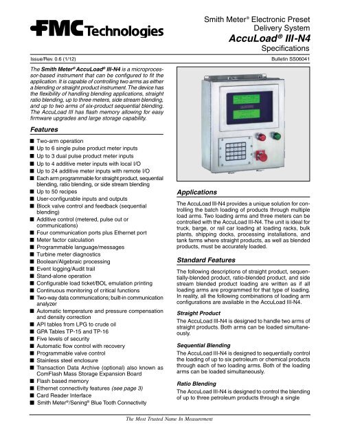
The Smith Meter ® AccuLoad ® III-N4 is a microprocessor-based<br />
instrument that can be configured to fit the<br />
application. It is capable of controlling two arms as either<br />
a blending or straight product instrument. The device has<br />
the flexibility of handling blending applications, straight<br />
ratio blending, up to three meters, side stream blending,<br />
and up to two arms of six-product sequential blending.<br />
The AccuLoad III has flash memory allowing for easy<br />
firmware upgrades and large storage capability.<br />
Features<br />
Two-arm operation<br />
Up to 6 single pulse product meter inputs<br />
Up to 3 dual pulse product meter inputs<br />
Up to 4 additive meter inputs with local I/O<br />
Up to 24 additive meter inputs with remote I/O<br />
Each arm programmable for straight product, sequential<br />
blending, ratio blending, or side stream blending<br />
Up to 50 recipes<br />
User-configurable inputs and outputs<br />
Block valve control and feedback (sequential<br />
blending)<br />
Additive control (metered, pulse out or<br />
communications)<br />
Four communication ports plus Ethernet port<br />
Meter factor calculation<br />
Programmable language/messages<br />
Turbine meter diagnostics<br />
Boolean/Algebraic processing<br />
Event logging/Audit trail<br />
Stand-alone operation<br />
Configurable load ticket/BOL emulation printing<br />
Continuous monitoring of critical functions<br />
Two-way data communications; built-in communication<br />
analyzer<br />
Automatic temperature and pressure compensation<br />
and density correction<br />
API tables from LPG to crude oil<br />
GPA Tables TP-15 and TP-16<br />
Five levels of security<br />
Automatic flow control with recovery<br />
Programmable valve control<br />
Stainless steel enclosure<br />
Transaction Data Archive (optional) also known as<br />
ComFlash Mass Storage Expansion Board<br />
Flash based memory<br />
Ethernet connectivity features (see page 3)<br />
Card Reader Interface<br />
■■<br />
Smith Meter ® /Sening ® Blue Tooth Connectivity<br />
Applications<br />
Smith Meter ® Electronic Preset<br />
Delivery System<br />
Bulletin <strong>SS06041</strong><br />
The AccuLoad III-N4 provides a unique solution for controlling<br />
the batch loading of products through multiple<br />
load arms. Two loading arms and three meters can be<br />
controlled with the AccuLoad III-N4. The unit is ideal for<br />
truck, barge, or rail car loading at loading racks, bulk<br />
plants, shipping docks, processing installations, and<br />
tank farms where straight products, as well as blended<br />
products, must be accurately loaded.<br />
Standard Features<br />
AccuLoad ® III-N4<br />
Specifications<br />
The following descriptions of straight product, sequentially-blended<br />
product, ratio-blended product, and side<br />
stream blended product loading are written as if all<br />
loading arms are programmed for that type of loading.<br />
In reality, all the following combinations of loading arm<br />
configurations are available in the AccuLoad III-N4.<br />
Straight Product<br />
The AccuLoad III-N4 is designed to handle two arms of<br />
straight products. Both arms can be loaded simultaneously.<br />
Sequential Blending<br />
The AccuLoad III-N4 is designed to sequentially control<br />
the loading of up to six petroleum or chemical products<br />
through each of two loading arms. Both of the loading<br />
arms can be loaded simultaneously.<br />
Ratio Blending<br />
The AccuLoad III-N4 is designed to control the blending<br />
of up to three petroleum products through a single<br />
The Most Trusted Name In <strong>Measurement</strong>
loading arm. All products flow through a metering<br />
system, are co-mingled downstream of the metering<br />
system, and flow through a single loading arm into<br />
a transport or into storage. Since both of the loading<br />
arms are programmable, the unit could be programmed<br />
for two load arms, one of which could be programmed<br />
as a two-product blender and the other as a straight<br />
product arm.<br />
Side Stream Blending<br />
The AccuLoad III-N4 is designed to control the blending<br />
of a minor product and a major product. The minor<br />
product is metered and controlled by a valve and the<br />
main product is free flowing. A second meter and control<br />
valve is located down stream of the blending point<br />
and measures/controls the flow of the blended product.<br />
The second arm could be programmed as a straight<br />
product arm.<br />
Wild Stream Blending<br />
The AccuLoad also supports Wild Stream Blending,<br />
which allows for continuous (no preset entered) ratio<br />
blending of products. One of the products can be uncontrolled<br />
(wild stream). This option is also available with the<br />
hybrid arm configuration. Wild Stream Blending supports<br />
“on the fly” blend percent changes and also for changing<br />
meters to accommodate varying flow rates.<br />
Temperature Compensation<br />
The temperature compensation option provides the<br />
customer with the capability of compensating for the<br />
variance in temperature from a reference temperature.<br />
This option is used with an RTD input or a temperature<br />
transducer and, excluding the accuracy of the fluid temperature<br />
measurement, will exactly match the proper<br />
volume correction factor of ASTM-D-1250-04 and API<br />
MPMS CH 11.1 - 2004 over the fluid temperature range<br />
of -40°F to 572°F (-40°C to 300°C). The following API<br />
tables can be programmed in the AccuLoad III: 5A,<br />
5B, 5D, 6, 6A, 6B, 6C, 6D, 23, 23A, 23B, 23D, 23E, 24,<br />
24A, 24B, 24D, 24E, 53, 53A, 53B, 53D, 54, 54A, 54B,<br />
54C, 54D, 59A, 59B, 59D, 60A, 60B, 60D, BR1A, BR1P,<br />
and BR2P.<br />
Pressure Compensation<br />
The pressure compensation option provides the customer<br />
with the capability of compensating the volume<br />
of product delivered at varying pressures per API Tables<br />
11.2.1 and 11.2.2, using a 4-20 mA pressure transducer<br />
input per preset position. This option also contains realtime<br />
control functions for maintaining system pressures<br />
at the meter to a minimally-acceptable, user-definable<br />
level (pressure transducer not included). This option<br />
is particularly useful for light products, such as LPG,<br />
where the compressibility factor varies a great deal with<br />
different pressures.<br />
Density Correction<br />
The density correction option provides the customer<br />
with the capability of correcting the volume of product<br />
delivered at varying densities. This can be either a frequency<br />
input or a 4-20 mA input.<br />
Metered Injectors, Piston Injectors and Smart<br />
Additives<br />
The AccuLoad III has been designed to provide maximum<br />
flexibility when it comes to additive control. The unit<br />
is capable of handling metered injectors, piston injectors<br />
and smart additives simultaneously.<br />
The AccuLoad is capable of controlling four additive<br />
injector metered systems. (See Hardware Options for<br />
additional injector systems.) The AccuLoad controls<br />
the additive solenoids to precisely inject the additive into<br />
the main product. It monitors the pulses of the additive<br />
meter and controls the amount of the additive, based<br />
on the incoming pulses from the additive meter and the<br />
main product meter.<br />
Additive monitoring and smart additives provide the<br />
capability for the AccuLoad to monitor the feedback<br />
from the piston injectors of the additive products. The<br />
AccuLoad monitors the injector feedback switches for<br />
a change of state and counts the errors and alarms if<br />
no change is detected within the cycle or a period of<br />
time, depending on how the unit is programmed. The<br />
AccuLoad will totalize the additive volume based on<br />
confirmation signals and a programmable volume per<br />
cycle. The totalized volume will print on the emulated<br />
load ticket printed on the shared printer output.<br />
For Smart additives, the firmware has also been designed<br />
with a Master/Slave type of communications,<br />
with the AccuLoad being the master and the Additive<br />
Injector System being the slave. The AccuLoad constantly<br />
interrogates the Additive Injector System for<br />
a change in status. The AccuLoad can be operated<br />
with communications control over the Smart Additive<br />
Injector System or with communication/pulse control.<br />
When the AccuLoad has communication control over the<br />
Additive System, it will constantly monitor the Additive<br />
System for its status, poll the additive totals, and signal<br />
the system when to inject the additive -- all through the<br />
communications line.<br />
The AccuLoad communications package has also been<br />
designed with a pass-through communications mode. In<br />
this mode of operation the supervisory computer can talk<br />
to the Additive Injector System through the communication<br />
lines that have been run to the AccuLoad and from<br />
the AccuLoad to the Additive Injector System(s).<br />
Dual Pulse Security<br />
This option provides continuous monitoring, error indication<br />
alarm, and correction of the pulse transmission for<br />
each preset position per API Petroleum <strong>Measurement</strong><br />
Standard, Chapter 5.5, Level A, and Institute of Petroleum<br />
Standard, IP 252/76, Part XIII, Section 1, Level A<br />
(PPS High-Security Pulse Transmitter is not included).<br />
The PPS High-Security Transmitter provides four signals:<br />
“A,” “A inverted,” “B,” and “B inverted.” The “A” and<br />
“B” signals are 90 electrical degrees out-of-phase and<br />
used for dual-pulse security. The “A” and “A inverted,”<br />
and “B” and “B inverted” signals are 180 electrical degrees<br />
out-of-phase and are used for transmitter power<br />
sensing. If power sensing is not required, only “A” and<br />
“B” are used for dual-pulse security.<br />
Page 2 • <strong>SS06041</strong> Issue/Rev. 0.6 (1/12)
Automated Proving Mode<br />
The AccuLoad III firmware provides an automated proving<br />
mode of operation. When the automated proving<br />
mode is activated the AccuLoad will calculate the meter<br />
factor for a proving run based on information that is<br />
obtained during the prove. The operator can select the<br />
flow rate and meter factor that is being proved through<br />
the keypad of the AccuLoad. After the prove is complete<br />
the operator enters the prover volume and prover<br />
temperature and the AccuLoad will calculate the new<br />
meter factor. The operator has the choice of downloading<br />
it to the program or ignoring it. The AccuLoad also<br />
has the capability of providing an average meter factor<br />
over a maximum of ten proves. This feature allows the<br />
operator to prove the meter on all four products, and<br />
four meter factors and associated flow rates for each<br />
product without having to enter the program mode for<br />
each product and meter factor.<br />
Boolean and Algebraic Processing<br />
The AccuLoad III provides the customer the flexibility to<br />
set-up inputs and outputs for tasks that are not standard<br />
in the unit. Through Boolean processing, relays can be<br />
turned on and off through equations and events set up<br />
by the customer. For example, a relay is required to<br />
close at the first trip point of the load. This can be set up<br />
using Boolean processing and does not require special<br />
software from Smith.<br />
Algebraic processing is also a feature that the customer<br />
can use to do simple mathematical calculations that are<br />
not in the unit. These calculations can then be used on<br />
the configurable reports for the current batch being run<br />
by the unit.<br />
Hardware Options<br />
AccuLoad Interface Control Board<br />
The AccuLoad Remote Mounted Interface Control Board<br />
provides additional flexibility to the AccuLoad's standard<br />
features. The optional AICB Board provides either ten<br />
additional metered additive injector systems or twenty<br />
additional programmable outputs per board set. With<br />
the optional AICB Board, the AccuLoad III with firmware<br />
has the capability of handling up to twelve metered<br />
injectors, twelve meter inputs, twelve solenoid valve<br />
outputs, and twelve additive pump outputs. One of the<br />
four communication ports is required to communicate<br />
with the AICB Board.<br />
ComFlash Mass Storage Expansion Board<br />
The optional hardware module provides additional nonvolatile<br />
memory to store transaction data. The module<br />
come with a 512 M SD card that has the capability of<br />
storing thousands of additional transactions. The module<br />
is only available on COM 4 and uses RS232 communications.<br />
The A3X also provides alarms for the expansion<br />
board to ensure proper operation. The Smith Meter ®<br />
Proximity Card Reader can also operate on COM 4 in<br />
conjunction with the ComFlash board.<br />
Card Reader<br />
The Smith Meter ® Card Reader can be added to the face<br />
of the AccuLoad III-N4. This option provides an integrally<br />
mounted RF-based proximity reader to the AccuLoad<br />
III. It is capable of interpreting multiple card formats<br />
and transmitting card data either to the AccuLoad III or<br />
directly to an automation system.<br />
Ethernet Connectivity Features<br />
ARP/RARP and DHCP support<br />
PING echo diagnostics<br />
SLIP<br />
FTP file transfer<br />
Smith protocol and Modbus protocol support over<br />
TCP/IP<br />
Limited HTTP server functionality<br />
Dynamic name server lookups (DNS client)<br />
Simple Mail Transport Protocol (SMTP)<br />
Post Office Protocol V3 (POP3)<br />
A collection of HTML and XML pages and CGI scripts<br />
Web server – command line argument passing<br />
Support for network printers (LPR client)<br />
The addition of a Remote Display/TCP daemon to the<br />
AccuLoad III<br />
Compliance with TCP/IP standards<br />
Specifications (AccuLoad III)<br />
Accuracy<br />
Calculated Accuracy: The gross at standard temperature<br />
to gross volume ratio, excluding the accuracy of<br />
fluid temperature measurement, will exactly match<br />
the proper volume correction factor of ASTM-D-1250-<br />
04 over the fluid temperature range of -40°F to 572°F<br />
(-40°C to 300°C).<br />
Temperature <strong>Measurement</strong> Accuracy: Fluid temperature<br />
is measured to within ±0.72°F (±0.4°C) over the<br />
fluid temperature range of -148°F to 572°F (-100°C<br />
to 300°C). Fluid temperature is measured to within<br />
±0.45°F (±0.25°C) over the fluid temperature range<br />
of 32°F to 572°F (0°C to 300°C).<br />
Stability: 0.1°F (0.06°C)/year.<br />
Flow Totalizing: Within one pulse of input frequency.<br />
Electrical Inputs<br />
AC Instrument Power:<br />
Universal input 100 to 240 Vac, 58W maximum, 48 to<br />
63 Hz. The AC circuitry is fuse-protected.<br />
Surge Current: 28A maximum for less than 0.1<br />
seconds.<br />
Power Interruption Tolerance: Interruption of power<br />
greater than .05 seconds (typical) will cause an<br />
orderly shut-down of the AccuLoad and the control<br />
valve will be immediately signaled to close.<br />
Note: A constant voltage transformer (CVT) is recommended if<br />
the available AC power is suspected not to comply with these<br />
specifications.<br />
Issue/Rev. 0.6 (1/12) <strong>SS06041</strong> • Page 3
Pulse Input:<br />
Type: High-speed, edge-triggered, optically isolated<br />
pulse transmitter input. The input pulse must rise<br />
above V (high min.) for a period of time and then<br />
fall below V (low) to be recognized as a pulse by<br />
AccuLoad III.<br />
V (High): 5 Vdc minimum to 28 Vdc maximum.<br />
V (Low): 1 Vdc maximum.<br />
Input Impedance: 1.8 KΩ.<br />
Pulse Resolution: 1 pulse/unit minimum, 9,999<br />
pulses/unit maximum.<br />
Frequency Range: 0 to 10.0 kHz.<br />
Response: Within one pulse to a step change in flow<br />
rate.<br />
Mode: Single, dual, dual with power sensing, density.<br />
Duty Cycle: 35/65 to 65/35 (on/off).<br />
Temperature Probe:<br />
Type: four-wire, 100 Ω Platinum Resistance Temperature<br />
Detector (PRTD).<br />
Temperature Coefficient: @ 32°F: 0.00214 Ω/Ω/°F<br />
(0.00385 Ω/Ω/°C).<br />
Temperature Range: -148°F to 572°F (-100°C to<br />
300°C).<br />
Offset: Temperature probe offset is program-adjustable<br />
through the AccuLoad keypad in ±0.1 degree<br />
increments in the unit of temperature measurement<br />
used.<br />
Self-calibrating: Lead length compensation that<br />
requires no resistance balancing of leads.<br />
Analog (4-20 mA):<br />
Type: Two-wire, 4-20 mA current loop receiver, isolated<br />
from ground, programmable as to function.<br />
Span Adjustment: Program-adjustable through the<br />
AccuLoad keypad or communication in tenths of the<br />
unit used.<br />
Input Burden: 50 Ω.<br />
Accuracy: ±0.025% of range.<br />
Resolution: One part in 65,536.<br />
Voltage Drop: 2 Volts maximum.<br />
Sampling Rate: One sample/300 mSec minimum.<br />
Analog (1-5 Vdc):<br />
Type: Two-wire, 1-5 Vdc voltage loop receiver, isolated<br />
from ground, programmable as to function.<br />
Span Adjustment: Program-adjustable through the<br />
AccuLoad keypad or communications in tenths of<br />
the unit used.<br />
Input Burden: 1 m Ω.<br />
Accuracy: ±0.025% of range<br />
Resolution: One part in 65,536.<br />
Sampling Rate: One sample/300 mSec minimum.<br />
AC Inputs:<br />
Type: Optically-isolated, solid-state voltage sensor.<br />
Input Voltage Range: 90 to 280 Vac.<br />
Pickup Voltage: 90 Vac minimum.<br />
Drop-out Voltage: 30 Vac maximum.<br />
Current at Maximum Voltage: 20 mA maximum.<br />
Input Resistance: 44,000 Ω typical.<br />
DC Inputs:<br />
Type: Optically-isolated solid state voltage sensors<br />
Input Voltage Range: 5 to 28 Vdc.<br />
Pickup Voltage: 5 Vdc minimum.<br />
Drop-out Voltage: Less than 1 volt.<br />
Current at Maximum Voltage: 20 mA maximum.<br />
Input Level Duration: 120 mSec minimum.<br />
Keypad:<br />
Type: Metal encapsulated, one-piece, sealed, no<br />
moving parts, piezoelectric design. Protected against<br />
the environment.<br />
Display:<br />
The Graphics Display is a 240 by 64 pixel graphic<br />
Liquid Crystal Display (LCD) modules with LED<br />
backlighting.<br />
Electrical Outputs<br />
DC Power:<br />
24 Vdc ±10%, 1 A maximum, short circuit protected.<br />
AC Outputs:<br />
Type: Optically-isolated, AC, solid-state relays. Userprogrammable<br />
as to function.<br />
Load Voltage Range: 90 to 280 Vac (rms), 48 to 63 Hz.<br />
Steady-State Load Current Range: 0.05A (rms) minimum<br />
to 1.0A (rms) maximum into an inductive load.<br />
Leakage Current at Maximum Voltage Rating: 5.2 mA<br />
(rms) maximum @ 240 Vac.<br />
On-State Voltage Drop: 2 Vac at maximum load.<br />
DC Outputs:<br />
Type: Optically-isolated solid state output. User-programmable<br />
as to function.<br />
Polarity: Programmable (normally open or normally<br />
closed).*<br />
Switch Blocking Voltage: 30 Vdc maximum.<br />
Load Current: 150 mA maximum with 0.6 volt drop.<br />
Note: *Power-down normally open.<br />
Analog (4-20 mA):<br />
Type: Two-wire, 4-20 mA current loop transmitter,<br />
isolated from ground, programmable as to function.<br />
Span Adjustment: Program adjustable through the<br />
AccuLoad keypad or through communications.<br />
Accuracy: ±0.025% of range.<br />
Resolution: One part in 65,536.<br />
Voltage Burden: 4 volts maximum.<br />
Analog (1-5 Vdc):<br />
Type: Two-wire, 1-5 Vdc voltage loop transmitter, isolated<br />
from ground, programmable as to function.<br />
Span Adjustment: Program adjustable through the<br />
AccuLoad keypad or through communications.<br />
Accuracy: ±0.025% of range.<br />
Page 4 • <strong>SS06041</strong> Issue/Rev. 0.6 (1/12)
Resolution: One part in 65,536.<br />
Pulse Output 1 & 2:<br />
Type: Optically-isolated solid state output. Pulser<br />
output units are program-selectable through the AccuLoad<br />
keypad or communications.<br />
Polarity: Programmable (normally open or normally<br />
closed).<br />
Switch Blocking Voltage (Switch Off): 30 Vdc maximum.<br />
Load Current (Switch On): 10 mA with 0.6 volts<br />
drop.<br />
Frequency Range: 0 to 3000 Hz.<br />
Duty Cycle: 50/50 (on/off).<br />
Pulse Output 3, 4 & 5:<br />
Type: Solid state relay digital output switch<br />
Load Current: 110mA max.<br />
Frequency Range: 0-125Hz<br />
Duty Cycle: 50/50 (on/off)<br />
Programmable maximum frequency output. All<br />
intended pulses will be eventually transmitted, the<br />
total period may increase to ensure all pulses are<br />
output.<br />
Note: When used, these outputs use the DC output popints on<br />
the KDC (DC output 1-3 respectively and also the 3 digital inputs<br />
1-3 respectively).<br />
Environment<br />
Ambient Operating Temperature<br />
-40 o F to 140 o F (-40 o C to 60 o C).<br />
Humidity:<br />
5 to 95% with condensation.<br />
Enclosure:<br />
Industrial type 4X.<br />
Approvals<br />
UL/CUL<br />
Class I, Division 2, Groups C & D; UNL-UL Enclosure<br />
4X, CNL-CSA Enclosure 4.<br />
Class I, Zone 2, Group IIB.<br />
UL/CUL File E23545 (N).<br />
AccuLoad III-N4 Weight: Approximately 35 lb (15.90 kg).<br />
Communications<br />
General<br />
Number of Ports: Four, plus Ethernet port.<br />
Configuration: Multi-drop network. Standard IT practices<br />
should be followed when connecting multiple<br />
AccuLoad IIIs via an Ethernet hub, router, or switch.<br />
Data Rate: Keypad-selectable to asynchronous data<br />
rates of 1,200, 2,400, 3,600, 4,800, 7,200, 9,600,<br />
19,200, or 38,400 bps (serial comm).<br />
Data Format: Programmable one start bit, programmable<br />
seven or eight data bits - even, odd, or no<br />
parity, one stop bit.<br />
Line Protocol: Half-duplex, full-duplex, no character<br />
echo.<br />
Data Structure: ASCII character-oriented, modeled<br />
after ISO Standard 1155.<br />
Protocol: Smith ASCII LRC, Smith ASCII CR, Smith<br />
ASCII binary, Modicon Modbus (PI-MBUS-300 Rev.<br />
D).<br />
AccuLoad II Style: Terminal Mode, Minicomputer<br />
Mode.<br />
Ethernet: 10/100 Base TRJ-45 8 or 10 pin UTP<br />
(unshielded twisted pair) connector.<br />
EIA-232 (1 dedicated, 2 selectable)<br />
Type: Interfaceable with EIA-232 data communication<br />
standards. Data transmitters are tri-state design.<br />
Typical Applications: Product receipt ticket printing<br />
(used with a stand-alone ASCII printer or as a backup<br />
in the standby mode with automation for BOL emulation)<br />
or communications with Product Management<br />
Automation Systems. Up to 16 AccuLoads can be<br />
connected onto the same transmit and receive data<br />
lines.<br />
EIA-485 (1 dedicated, 2 selectable)<br />
Type: Interfaceable with EIA-485 data communication<br />
standards.<br />
Typical Application: Communications with Product<br />
Management Automation Systems.<br />
Number of Units per Communication Line: Up to 32<br />
AccuLoads can be connected onto the same transmit<br />
and receive data lines.<br />
Specifications (Red and Green Indicating<br />
Light Units – Optional)<br />
Electrical Ratings<br />
Bulbs:<br />
LED Lamp, 120V AC in Red or Green<br />
Terminals:<br />
Saddle clamp type for 1 x 22 AWG<br />
Specifications (Stop Button – Optional)<br />
Electrical Ratings<br />
Contact Block:<br />
A600 (AC): 120V maximum<br />
Make and Emergency Interrupting Capacity (Amps):<br />
60 (120V); 30 (240V)<br />
Normal Load Break (Amps): 6 (120V); 3 (240V)<br />
Thermal Current (Amp): 10<br />
Voltamperes: Maximum Make 7200; Maximum Break<br />
720<br />
Contact Type:<br />
1N0-1NC (Momentary)<br />
Color: Black<br />
Issue/Rev. 0.6 (1/12) <strong>SS06041</strong> • Page 5
Terminals:<br />
Stainless steel saddle clamp type for 1 x 18 - 14<br />
AWG (0.75 - 2.5 sq. mm) solid or stranded copper<br />
conductor<br />
Specifications (AICB Board – Optional)<br />
(Remote Mount)<br />
Electrical Inputs<br />
DC Instrument Power:<br />
24 Vdc ±10%, 1 watt maximum<br />
Pulse Input:<br />
Type: High-speed, edge-triggered, optically isolated,<br />
compatible with contact closure, open collector or<br />
voltage sink/source pulse transmitter input. The input<br />
pulse must rise above V (high min.) for a period of<br />
time and then fall below V (low) to be recognized as<br />
a pulse.<br />
V (High): 10 Vdc minimum to 24 Vdc maximum.<br />
V (Low): 8 Vdc maximum.<br />
Pulse Resolution: 1 pulse/unit minimum, 9,999 pulses/<br />
unit maximum.<br />
Frequency Range: 0 to 5 kHz.<br />
Response: Within one pulse to a step change in flow<br />
rate.<br />
Minimum Pulse Width: 50 uS.<br />
Electrical Outputs<br />
AC Outputs:<br />
Type: Optically-isolated, AC, solid-state relays. Userprogrammable<br />
by the host as to function.<br />
Load Voltage Range: 90 to 275 Vac (rms), 48 to 63 Hz.<br />
Steady-State Load Current Range: 0.05A (rms) minimum<br />
to 0.5A (rms) maximum into an inductive load.<br />
Leakage Current at Maximum Voltage Rating: 0.1mA<br />
(rms) maximum at 240 Vac.<br />
On-State Voltage Drop: 1.5 Vac at maximum load.<br />
Environment<br />
Ambient Operating Temperature<br />
-40 o F to 140 o F (-40 o C to 60 o C).<br />
Humidity:<br />
5 to 95% with condensation.<br />
Remote Enclosure:<br />
Explosion-proof (NEMA 7, Class I, Groups C and D)<br />
and watertight (NEMA 4X), IP65<br />
Approvals (Remote Enclosure)<br />
UL/CUL:<br />
Class I, Division 1, Groups C and D; UNL-UL Enclosure<br />
4X, CNL-CSA Enclosure 4.<br />
Class I, Zone 1, AEx d IIB T6, IP65.<br />
Page 6 • <strong>SS06041</strong> Issue/Rev. 0.6 (1/12)
Programmable Inputs/Outputs<br />
Digital Inputs AC DC Total<br />
Standard 5 6 11<br />
Optional (One Remote AICB) 5 16 21<br />
Digital Outputs AC DC Total<br />
Standard 11 3 14<br />
Optional (One Remote AICB) 31 13 44<br />
Analog Inputs/Outputs - Up to 6<br />
Modeling 1 Analog Modules 2<br />
ALIII-N4 ⎯ ALX2 ⎯ 1 ⎯ 1 ⎯ 1 ⎯ A00000 ⎯ 10<br />
Number of Fuse Holders<br />
Hardware Model<br />
Designation<br />
(0 - 10)<br />
N4 - NEMA IV<br />
Firmware<br />
ALX1 - 1 Arm Operation<br />
ALX2 - 2 Arm Operation<br />
Digit 1 - Number of RTDs<br />
Digit 2 - Number of 4-20 mA inputs<br />
Digit 3 - Number of 4-20 mA outputs<br />
Digit 4 - Number of 1-5 Vdc inputs<br />
Digit 5 - Number of 1-5 Vdc outputs<br />
Stop Button<br />
0 - None<br />
1 - 120 / 230 Volt<br />
Hardware Options<br />
0 - None<br />
1 - Card Reader<br />
Indicator Lights<br />
0 - None<br />
1 - 120 Volt (Red, Green)<br />
2 - 240 Volt (Red, Green)<br />
3 - 120 Volt (Green, Green)<br />
AICB Modeling<br />
REM ⎯ XP ⎯ A<br />
Model Designation<br />
Hardware Option<br />
A = AICB Board<br />
Housing<br />
XP - Explosion Proof<br />
1 A complete model number is required when ordering the AccuLoad III.<br />
2 Maximum of 6 Analog Modules per AccuLoad III.<br />
Issue/Rev. 0.6 (1/12) <strong>SS06041</strong> • Page 7
14.0"<br />
(356)<br />
.31 DIA.<br />
7.19"<br />
(183)<br />
16.0"<br />
(406)<br />
16.75"<br />
(425)<br />
1 2 3 F1 F2<br />
4 5 6 Set Print<br />
7 8 9 Clear Start<br />
STOP<br />
+/- 0 . Enter Stop<br />
12.0"<br />
(305 )<br />
Three 1.75" (45)<br />
Conduit Entrances<br />
4.0"<br />
(102)<br />
3.0"<br />
(76)<br />
6.0"<br />
(152)<br />
3.0"<br />
(76)<br />
4.0"<br />
(102)<br />
Note: Dimensions — Inches to the nearest tenth (millimetres to the nearest whole mm), each independently dimensioned from respective<br />
engineering drawings.<br />
Figure 1 – Enclosure Dimensions<br />
14.0"<br />
(356)<br />
Page 8 • <strong>SS06041</strong> Issue/Rev. 0.6 (1/12)
2.50"<br />
(64)<br />
6.50"<br />
(165)<br />
13.4"<br />
(340)<br />
10.4"<br />
(264)<br />
2.00"<br />
(51)<br />
6.2"<br />
(157)<br />
1.00" - 11.5" NPT<br />
Conduit Entrance<br />
1.50"<br />
(38)<br />
9.75"<br />
(248)<br />
1.50"<br />
(38)<br />
1.25" - 11.5" NPT<br />
Conduit Entrances<br />
Typical 2 Places<br />
Figure 2 – Remote Housing (Optional AICB)<br />
Issue/Rev. 0.6 (1/12) <strong>SS06041</strong> • Page 9
Revisions included in <strong>SS06041</strong> Issue/Rev. 0.6 (1/12):<br />
Page 6: Removed CENELEC (DEMKO) EEx d IIB T6, IP65 Class I, Zone 1, Ex d IIB T6.<br />
The specifications contained herein are subject to change without notice and any user of said specifications should verify from the manufacturer that the specifications are currently<br />
in effect. Otherwise, the manufacturer assumes no responsibility for the use of specifications which may have been changed and are no longer in effect.<br />
Contact information is subject to change. For the most current contact information, visit our website at www.fmctechnologies.com/measurementsolutions and click on the<br />
“Contact Us” link in the left-hand column.<br />
Headquarters:<br />
500 North Sam Houston Parkway West, Suite 100, Houston, TX 77067 USA, Phone: +1 (281) 260 2190, Fax: +1 (281) 260 2191<br />
<strong>Measurement</strong> Products and Equipment:<br />
Erie, PA USA +1 (814) 898 5000<br />
Ellerbek, Germany +49 (4101) 3040<br />
Barcelona, Spain +34 (93) 201 0989<br />
Beijing, China +86 (10) 6500 2251<br />
Buenos Aires, Argentina +54 (11) 4312 4736<br />
Burnham, England +44 (1628) 603205<br />
Dubai, United Arab Emirates +971 (4) 883 0303<br />
Los Angeles, CA USA +1 (310) 328 1236<br />
Melbourne, Australia +61 (3) 9807 2818<br />
Moscow, Russia +7 (495) 5648705<br />
Singapore, +65 6861 3011<br />
Visit our website at www.fmctechnologies.com/measurementsolutions<br />
Printed in U.S.A. © 1/12 <strong>FMC</strong> <strong>Technologies</strong> <strong>Measurement</strong> <strong>Solutions</strong>, Inc. All rights reserved. <strong>SS06041</strong> Issue/Rev. 0.6 (1/12)<br />
Integrated <strong>Measurement</strong> Systems:<br />
Corpus Christi, TX USA +1 (361) 289 3400<br />
Kongsberg, Norway +47 (32) 286700<br />
Dubai, United Arab Emirates +971 (4) 883 0303


