Hard Flanged Circuit Balancing Valves - Armstrong Pumps
Hard Flanged Circuit Balancing Valves - Armstrong Pumps
Hard Flanged Circuit Balancing Valves - Armstrong Pumps
- No tags were found...

Create successful ePaper yourself
Turn your PDF publications into a flip-book with our unique Google optimized e-Paper software.
®<br />
FILE NO.: 36.88<br />
DATE: November 20,1998<br />
SUPERSEDES: NEW<br />
DATE: NEW<br />
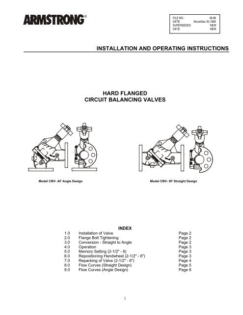
INSTALLATION AND OPERATING INSTRUCTIONS<br />
HARD FLANGED<br />
CIRCUIT BALANCING VALVES<br />
Model CBV- AF Angle Design<br />
Model CBV- SF Straight Design<br />
INDEX<br />
1.0 Installation of Valve Page 2<br />
2.0 Flange Bolt Tightening Page 2<br />
3.0 Conversion - Straight to Angle Page 2<br />
4.0 Operation Page 3<br />
5.0 Memory Setting (2-1/2" - 6) Page 3<br />
6.0 Repositioning Handwheel (2-1/2" - 6") Page 3<br />
7.0 Repacking of Valve (2-1/2" - 6") Page 4<br />
8.0 Flow Curves (Straight Design) Page 5<br />
9.0 Flow Curves (Angle Design) Page 6<br />
1
1.0 INSTALLATION<br />
1.1 To ensure accuracy of measurement, the CBV<br />
should be located at least five pipe diameters<br />
downstream from any fitting and at least ten pipe<br />
diameters downstream from a pump. Two pipe<br />
diameters downstream from the CBV should be<br />
free of any fitting (as illustrated in Fig 1).<br />
3.0 CONVERSION (Straight to Angle)<br />
3.1 Open the valve one complete turn.<br />
3.2 Remove the body bolts from the valve body.<br />
3.3 Rotate one-half of the valve body, 180, making<br />
sure the seat and "O" ring stay in position and do<br />
not get nicked or cut.<br />
3.4 Replace the body bolts and tighten evenly.<br />
Fig. 1<br />
1.2 CBV valves must be installed with flow in the<br />
direction of the arrow on the valve body. Easy<br />
access to the probe metering ports (P.M.P's) and<br />
handwheel must be provided.<br />
1.3 CBV valves can be installed in horizontal or<br />
vertical piping. The metering ports should never<br />
be installed below the pipe (pointing down), as<br />
this will allow system sediment to accumulate in<br />
the ports. (Illustrated below for horizontal piping in<br />
Fig. 2).<br />
Fig. 3 With no arrows visible, the Inner Scale set at 0<br />
on the indicator line aligned with the 0 on the<br />
Outer Scale; the valve is closed.<br />
Fig. 4<br />
Shows a valve setting of 2.0, indicating that the<br />
valve is partially open.<br />
Fig. 2<br />
(1) Metering Port (2) Body Port & (3) Handwheel<br />
Drain<br />
1.4 CBV angle-style valves are designed to replace<br />
piping elbows.<br />
1.5 Metering ports and body plugs may be<br />
interchanged for improved accessibility.<br />
2.0 BOLT TIGHTENING<br />
2.1 Tighten all bolts evenly in standard star pattern.<br />
When used with a "raised face" flange, there will<br />
be a gap between the faces on the outer flange<br />
diameters.<br />
2<br />
Fig. 5 With all arrows visible, the Inner Scale, set at 6<br />
and the indicator line aligned with Outer Scale 0; the<br />
valve setting is 6.0 and the valve is fully open.
4.0 OPERATION<br />
4.1 The valve operates from closed (Fig.3) to fully open<br />
by a counterclockwise rotation of the red handwheel.<br />
Using five (5) 380 turns far the 2-1/2" and 3" valves, six<br />
(6) turns for the 4", 5", and 6" valves, 12 turns for the 8"<br />
and 10" valves and 14 turns for the 12" valve. Two scales<br />
indicate the position of the valve.<br />
Inner Scale (Fig.4&5)- This sleeve has a vertical arrowed<br />
scale which indicated the number of full turns the valve<br />
have been opened<br />
Outer Scale (Fig 4&5)- This scale is a micrometer-type<br />
scale marked 0-9 at the tapered base of the handwheel.<br />
Each gives 1/10th indications for each 360 turn of<br />
opening against the indicator line of the Inner Scale.<br />
Connect meter quick-disconnect hoses to metering ports<br />
as follows:<br />
• Remove protective cap from metering ports<br />
• Insert and lock the meter probe into the metering<br />
ports<br />
4.2 The hose with the red fitting upstream: the hose with<br />
the blue fitting downstream.<br />
4.3 CAUTION: The probe should not be left inserted into<br />
the fitting for prolonged periods of time; overnight, etc, as<br />
leakage of the P.M.P, may occur when the probe is<br />
removed.<br />
The locking nut on the probe is designed to hold it in the<br />
P.M.P. when taking readings in systems having a high<br />
working pressure. As sealing is accomplished internally<br />
on the probe stem, it is only necessary to tighten the<br />
locking nut finger-tight. Overtightening may cause<br />
damage to the P.M.P. or locking nut threads.<br />
4.4 Safety glasses should be used.<br />
4.5 Before taking a flow measurement reading, set the<br />
valve to its fully open (4.0) or at a preset position<br />
Read the pressure drop across the valve with an<br />
<strong>Armstrong</strong> CBDM-135/60. Determine GPM now by<br />
use of valve C v , curve an Pages 5 and 6 or the<br />
<strong>Armstrong</strong> Circular Slide Rule.<br />
BODY<br />
"O" RING<br />
INDICATOR HANDWHEEL<br />
SLEEVE<br />
LOCK COLLAR<br />
RETAINING<br />
BOLT<br />
5.0 MEMORY SETTING (Fig. 6)<br />
2-1/2"- 6" <strong>Valves</strong><br />
5.1 After the valve has been adjusted to its balance set<br />
point and without moving the handwheel, remove the<br />
retaining bolt from the end of the handwheel using a 1/4"<br />
Allen wrench.<br />
5.2 Carefully remove the handwheel and turn indicator<br />
sleeve assembly, leaving the valve at its balance set<br />
point.<br />
53 Turn the plastic memory stop (clockwise) down until it<br />
stops. Finger-tight pressure is sufficient. Do not overtighten.<br />
5.4 Holding the memory stops in position, turn the lock<br />
collar (clockwise) down until it stops against the valve<br />
bonnet. The memory has now been set.<br />
5.5 With the handwheel/turn indicator sleeve assembly<br />
still at its balance set point indication, reinstall them on<br />
the valve stem and hold in place with the 1/4" retaining<br />
bolt.<br />
CAUTION: Care must be taken not to rotate the valve<br />
stem or change the handwheel/indicator setting while<br />
setting the memory.<br />
6.0 REPOSITIONING HANDWHEEL<br />
2-1/2"- 6" <strong>Valves</strong><br />
6.1 The handwheel can be removed and repositioned in<br />
any of six positions around the stem.<br />
a) Close valve fully.<br />
b) Remove handwheel-retaining bolt.<br />
c) Remove handwheel and turn indicator sleeve<br />
by grasping the handwheel and pulling away<br />
from the valve body along the stem.<br />
d) Select a new position for easy reading and<br />
with the sleeve and handwheel held together<br />
in the closed position (0.0), push them back<br />
over the bonnet head and valve stem.<br />
e) Replace handwheel-retaining bolt.<br />
f) Open valve.<br />
6.2 If handwheel is removed for any reason, it is<br />
important to first close the valve and then replace<br />
the handwheel per 6.1 d) and e) above.<br />
BONNET<br />
MEMORY STOP<br />
STEM<br />
Fig. 6<br />
PLUG<br />
GASKET<br />
3
7.0 REPACKING CBV UNDER FULL<br />
SYSTEM PRESSURE<br />
2-1/2"- 6" <strong>Valves</strong><br />
7.1 Open valve fully to its memory setting and, on a<br />
piece of paper, record the valve setting.<br />
7.2 Remove the handwheel/indicator sleeve assembly<br />
as per 5.1 and 5.2.<br />
7.3 Loosen the lockcollar by turning it counter-clockwise<br />
until it seats against the top of the memory stop.<br />
7.4 Remove the memory stop/lockcollar assembly by<br />
turning the plastic memory stop counter-clockwise.<br />
7.5 Using the handwheel WITH THE INDICATOR<br />
SLEEVE REMOVED, turn the valve stem counterclockwise<br />
until the valve is fully open and will not<br />
turn any further (45 ft. Ibs.). A step on the valve plug<br />
has now been back-seated against the upper<br />
portion of the valve body (metal-to-metal).<br />
7.7 Clean exposed portion of valve stem (Do not<br />
scratch).<br />
7.8 Remove and replace the '0' ring and gasket.<br />
7.9 Install the valve bonnet.<br />
7.10 Replace memory stop/lockcollar assembly into the<br />
valve bonnet.<br />
7.11 Close the valve fully by turning the stem in a clockwise<br />
direction. Tightening valve bonnet is<br />
necessary to stop any leaks.<br />
7.12 Replace handwheel/indicator sleeve assembly per<br />
6.1 d) and a) above.<br />
7.13 Open valve to balance set point as recorded in 7.1.<br />
7.14 Reset memory per 5.0.<br />
7.6 The valve bonnet may now be removed. There may<br />
be slight leakage, as the metal-to-metal backseating<br />
does not provide a drip-tight seal.<br />
4
Handwheel Position<br />
8.0 FLOW CURVES<br />
STRAIGHT DESIGN<br />
CBV-21/2"S<br />
Handwheel Position<br />
Handwheel Position<br />
CBV-3" S<br />
CBV-4" S<br />
Handwheel Position<br />
Handwheel Position<br />
CBV-5" S<br />
CBV-6" S<br />
5
9.0 FLOW CURVES<br />
ANGLE DESIGN<br />
Handwheel Position<br />
Handwheel Position<br />
Handwheel Position<br />
Handwheel Position<br />
Handwheel Position<br />
S.A. <strong>Armstrong</strong> Limited<br />
23 Bertrand Avenue<br />
Toronto, Ontario<br />
Canada, M1L 2P3<br />
Tel: (416) 755-2291<br />
Fax: (416) 759-9101<br />
Visit us at www.armstrongpumps.com<br />
<strong>Armstrong</strong> <strong>Pumps</strong> Limited<br />
Peartree Road, Stanway<br />
Colchester, Essex<br />
United Kingdom, C03 5JX<br />
Tel: 01206-579491<br />
Fax: 01206-760532<br />
© S.A. <strong>Armstrong</strong> Limited 1998<br />
6<br />
<strong>Armstrong</strong> <strong>Pumps</strong> Inc.<br />
93 East Avenue<br />
Buffalo, New York<br />
U.S.A. 14120-6594<br />
Tel: (716) 693-8813<br />
Fax: (716) 693-8970<br />
<strong>Armstrong</strong> Darling Inc.<br />
2200 Place Transcanadienne<br />
Montreal, Quebec<br />
Canada, H9P 2X5<br />
Tel: (514) 421-2424<br />
Fax: (514) 421-2436