ITAL GROUP MOTOR R8D

You also want an ePaper? Increase the reach of your titles
YUMPU automatically turns print PDFs into web optimized ePapers that Google loves.
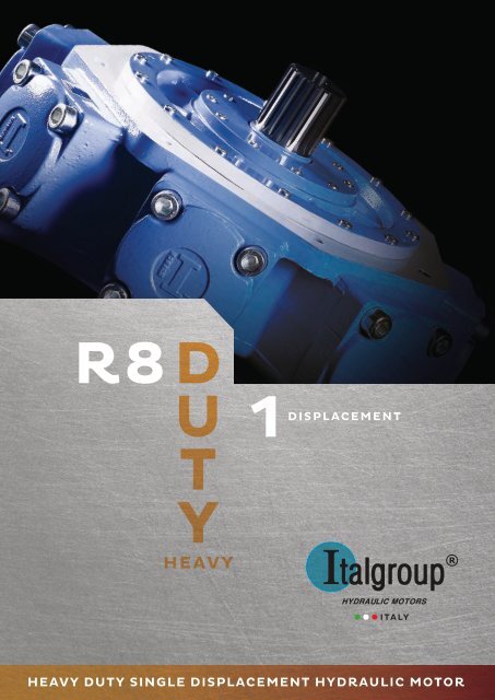
R8<br />
D<br />
U<br />
TY<br />
1DISPLACEMENT<br />
HEAVY<br />
<strong>ITAL</strong>Y<br />
HEAVY DUTY SINGLE DISPLACEMENT HYDRAULIC <strong>MOTOR</strong>
<strong>R8D</strong> SERIES<br />
TECHNICAL CATALOGUE<br />
The data specified into the catalogue are for product description purpose only<br />
and must not be interpreted as warranted characteristics in legal sense.<br />
Italgroup S.r.l. reserves the right to implement modifications without notice.<br />
All partial or total reproduction and copy without written authorization of Italgroup<br />
S.r.l. is strictly forbidden.<br />
©2018 <strong>ITAL</strong><strong>GROUP</strong> S.R.L. - ALL RIGHTS RESERVED -<br />
<strong>R8D</strong> rev.01 - Jan. 2019
GENERAL INDEX<br />
FORMULAS Pag. 3<br />
INTRODUCTION - GENERAL INFORMATION Pag. 4 - 5<br />
<strong>MOTOR</strong> TECHNICAL DATA Pag. 6 - 7<br />
INTERCHANGEABILITY CHART Pag. 8<br />
<strong>R8D</strong> ORDERING CODE Pag. 9<br />
HYDRAULIC FLUID RECOMMENDATIONS Pag. 10 - 11<br />
DRAIN RECOMMENDATIONS - FLUSHING Pag. 12 - 13<br />
STANDARD SHAFT SEAL FEATURES Pag. 14 - 15<br />
<strong>MOTOR</strong> INSTALLATION AND STARTUP Pag. 16 - 18<br />
<strong>MOTOR</strong> HANDLING AND STORAGE Pag. 19 - 20<br />
MAINTENANCE OPERATION Pag. 21<br />
INSTRUCTION AND ADVICES Pag. 22<br />
SPECIAL FEATURES Pag. 23<br />
TROUBLESHOOTING Pag. 24 - 25<br />
UNIT CONVERSIONS Pag. 26<br />
<strong>R8D</strong> H2 Pag. 27 - 36<br />
<strong>R8D</strong> H3 Pag. 37 - 50<br />
<strong>R8D</strong> H4 Pag. 51 - 69<br />
<strong>R8D</strong> H45 Pag. 71 - 79<br />
<strong>R8D</strong> H5 Pag. 79 - 99<br />
<strong>R8D</strong> H55 Pag. 101 - 113<br />
<strong>R8D</strong> H6 Pag. 115 - 133<br />
<strong>R8D</strong> H7 Pag. 135 - 149<br />
<strong>R8D</strong> H8 Pag. 151 - 162<br />
<strong>R8D</strong> H9 Pag. 163 - 173<br />
<strong>MOTOR</strong> DISTRIBUTORS Pag. 174 - 175<br />
TACHOMETERS Pag. 177 - 180<br />
SPLINED BILLETS - SPLINED BARS Pag. 181 - 185<br />
ADAPTOR FLANGES Pag. 186 - 187<br />
VALVES Pag. 189 - 206<br />
CONTACT US - REACH US Pag. 207<br />
The data specified into the catalogue are for product description purpose only and must not be interpreted as warranted characteristics in legal sense. Italgroup S.r.l. reserves the<br />
right to implement modifications without notice. All partial or total reproduction and copy without written authorization of Italgroup S.r.l. is strictly forbidden.
<strong>ITAL</strong><strong>GROUP</strong> <strong>MOTOR</strong>S <strong>R8D</strong> SERIES TECHNICAL CATALOGUE<br />
<strong>R8D</strong> rev.01 - Jan. 2019
FORMULAS<br />
Torque [Nm]<br />
=<br />
Specific torque [Nm/bar]<br />
*<br />
Pressure [bar]<br />
Torque [Nm]<br />
=<br />
Displacement [cc/Rev]<br />
62.8<br />
*<br />
Pressure [bar]<br />
Power [kW]<br />
=<br />
Torque [Nm]<br />
*<br />
9549<br />
Speed [rpm]<br />
Power [CV]<br />
=<br />
Torque [Nm]<br />
*<br />
7023<br />
Speed [rpm]<br />
Speed [rpm]<br />
=<br />
Flow [l/min] * 1000<br />
Displacement [cc/Rev]<br />
Displacement [cc/Rev]<br />
=<br />
Torque [Nm]<br />
*<br />
Pressure [bar]<br />
62,8<br />
Flow [l/min]<br />
=<br />
Displacement [cc/Rev] * Speed [rpm]<br />
1000<br />
The data specified into the catalogue are for product description purpose only and must not be interpreted as warranted characteristics in legal sense. Italgroup S.r.l. reserves the<br />
right to implement modifications without notice. All partial or total reproduction and copy without written authorization of Italgroup S.r.l. is strictly forbidden.<br />
3
<strong>ITAL</strong><strong>GROUP</strong> <strong>MOTOR</strong>S <strong>R8D</strong> SERIES TECHNICAL CATALOGUE<br />
INTRODUCTION<br />
GENERAL INFORMATION<br />
Carefully read the use and maintenance manual before start-up the motor. The<br />
use and maintenance manual must be placed near to motor installation location<br />
in order to guarantee operators easy access to the instruction manual. For further<br />
information please contact Italgroup.<br />
<strong>MOTOR</strong> DESCRIPTION<br />
<strong>R8D</strong> series motors are radial piston hydraulic motors (generally indicated as LSHT motors,<br />
low speed high torque motors) with a rotating shaft (1) and a stationary housing (2). The pistons<br />
(4) are located radially and the working fluid provide the mechanical force that push<br />
the pistons against the eccentric shaft, providing the shaft ouput torque. The inlet and outlet<br />
flow to and from the pistons is regulated by a distributor (5), that provides the oil distribution<br />
correct timing. The pistons transfer the forces to the eccentric shaft through a connecting rod<br />
(3). Acting in the adequate way (increasing or reducing the oil flow coming from the pump)<br />
the motor rotational speed can be increased or reduced. The motor design guarantee extremely<br />
high starting torque and high mechanical working efficiency. Respecting the limitation<br />
of working parameters (indicated into the technical datasheets) and all recommendations (including<br />
fluid recommendations), high motor lifetimes are obtained and very low maintenance<br />
requirements are needed.<br />
4<br />
3<br />
2<br />
5<br />
1<br />
4<br />
<strong>R8D</strong> rev.01 - Jan. 2019
<strong>R8D</strong> SERIES<br />
Hydraulic motors of the <strong>R8D</strong> series are single displacement crankshaft radial piston motors. Thanks to great<br />
variety of accessories <strong>R8D</strong> series can be used in a wide range of applications such as:<br />
• marine equipments<br />
• winches<br />
• offshore equipments<br />
• conveyors<br />
• injection moulding machines<br />
• steel bending machines<br />
• fork lifts trucks<br />
• skid steer loaders<br />
• dumpers<br />
• agricultural and forestry machines<br />
• municipal vehicles<br />
• airport machinery<br />
PRODUCT FEATURES:<br />
High volumetric and mechanical efficiencies<br />
Very smooth running at low speeds<br />
High starting torque / constant torque<br />
Wide speed range<br />
Compact Design<br />
Low maintenance and high reliability<br />
Bi-directional<br />
High radial and axial force allowed<br />
Speed sensor available<br />
Built-in valves available<br />
The data specified into the catalogue are for product description purpose only and must not be interpreted as warranted characteristics in legal sense. Italgroup S.r.l. reserves the<br />
right to implement modifications without notice. All partial or total reproduction and copy without written authorization of Italgroup S.r.l. is strictly forbidden.<br />
5
<strong>ITAL</strong><strong>GROUP</strong> <strong>MOTOR</strong>S <strong>R8D</strong> SERIES TECHNICAL CATALOGUE<br />
<strong>MOTOR</strong> TECHNICAL DATA<br />
Motor Size Displacement Theoretical<br />
torque<br />
Max cont.<br />
pressure<br />
Max cont.<br />
speed<br />
Peak speed<br />
(**)<br />
Max cont.<br />
power (*)<br />
Max<br />
power<br />
Dry<br />
weight<br />
[cc] [Nm/bar] [bar] [rpm] [rpm] [kW] [kW] [kg]<br />
<strong>R8D</strong> 300 H2 314 5 270 900 1100 45 66 42<br />
<strong>R8D</strong> 350 H3 342 5.4 270 850 950 85 130 68<br />
<strong>R8D</strong> 400 H3 398 6.3 270 750 860 85 130 68<br />
<strong>R8D</strong> 450 H3 452 7.2 270 650 760 85 130 68<br />
<strong>R8D</strong> 500 H3 492 7.8 270 600 690 85 130 68<br />
<strong>R8D</strong> 600 H3 594 9.5 270 500 570 85 130 68<br />
<strong>R8D</strong> 700 H3 707 11.2 170 440 500 78 118 68<br />
<strong>R8D</strong> 500 H4 493 7.8 270 700 800 130 160 92<br />
<strong>R8D</strong> 600 H4 584 9.3 270 700 800 130 160 92<br />
<strong>R8D</strong> 700 H4 714 11.4 270 500 580 130 160 92<br />
<strong>R8D</strong> 800 H4 792 12.6 270 450 530 130 160 92<br />
<strong>R8D</strong> 850 H4 847 13.5 270 420 490 130 160 92<br />
<strong>R8D</strong> 900 H4 904 14.4 270 400 460 130 160 92<br />
<strong>R8D</strong> 1000 H4 992 15.8 270 355 405 130 160 92<br />
<strong>R8D</strong> 1250 H4 1247 19.8 200 280 320 102 130 92<br />
<strong>R8D</strong> 1100 H45 1182 18.8 250 400 450 158 190 120<br />
<strong>R8D</strong> 1400 H45 1376 21.9 250 350 400 158 190 120<br />
<strong>R8D</strong> 900 H5 941 15 270 550 600 178 210 173<br />
<strong>R8D</strong> 1000 H5 1094 17.4 270 500 550 178 210 173<br />
<strong>R8D</strong> 1200 H5 1231 19.6 270 450 510 178 210 173<br />
<strong>R8D</strong> 1400 H5 1376 21.9 270 410 470 178 210 173<br />
<strong>R8D</strong> 1500 H5 1528 24.3 270 390 450 178 210 173<br />
<strong>R8D</strong> 1600 H5 1648 26.2 270 370 425 178 210 173<br />
<strong>R8D</strong> 1800 H5 1815 28.9 250 340 390 178 210 173<br />
<strong>R8D</strong> 2000 H5 2034 32.4 190 280 310 140 160 173<br />
<strong>R8D</strong> 1800 H55 1800 28.7 270 265 290 190 220 203<br />
<strong>R8D</strong> 2000 H55 1962 31.2 270 245 270 190 220 203<br />
<strong>R8D</strong> 2100 H55 2035 32.4 270 235 260 190 220 203<br />
<strong>R8D</strong> 2150 H55 2126 33,8 270 235 260 190 220 203<br />
<strong>R8D</strong> 2200 H55 2193 34,9 270 220 240 190 220 203<br />
<strong>R8D</strong> 2300 H55 2293 36.5 250 210 235 180 210 203<br />
<strong>R8D</strong> 2400 H55 2393 38.1 250 190 220 170 210 203<br />
<strong>R8D</strong> 1800 H6 1866 29.7 270 350 400 220 245 308<br />
<strong>R8D</strong> 2000 H6 1993 31.7 270 350 400 220 245 308<br />
<strong>R8D</strong> 2200 H6 2206 35.1 270 325 375 220 245 308<br />
<strong>R8D</strong> 2500 H6 2525 40.2 270 285 325 220 245 308<br />
<strong>R8D</strong> 2800 H6 2807 44.7 270 250 290 220 245 308<br />
<strong>R8D</strong> 3000 H6 2983 47.5 270 235 270 220 245 308<br />
<strong>R8D</strong> 3200 H6 3289 52.4 270 210 240 220 245 308<br />
<strong>R8D</strong> 3500 H6 3479 55.4 270 200 230 210 235 308<br />
6<br />
<strong>R8D</strong> rev.01 - Jan. 2019
Motor Size Displacement Theoretical<br />
torque<br />
Max cont.<br />
pressure<br />
Max cont.<br />
speed<br />
Peak<br />
speed (**)<br />
Max cont.<br />
power (*)<br />
Max<br />
power<br />
Dry<br />
weight<br />
[cc] [Nm/bar] [bar] [rpm] [rpm] [kW] [kW] [kg]<br />
<strong>R8D</strong> 3400 H7 3413 54.3 270 200 220 238 265 405<br />
<strong>R8D</strong> 3600 H7 3650 58.1 270 185 210 238 265 405<br />
<strong>R8D</strong> 3900 H7 3907 62.2 270 175 200 238 265 405<br />
<strong>R8D</strong> 4300 H7 4343 69.1 270 160 190 238 265 405<br />
<strong>R8D</strong> 4600 H7 4616 73.5 270 150 190 238 265 405<br />
<strong>R8D</strong> 5000 H7 5088 81.0 270 140 180 238 265 405<br />
<strong>R8D</strong> 5400 H7 5384 85.7 270 130 170 230 258 405<br />
<strong>R8D</strong> 3000 H8 3020 48.1 270 240 300 215 236 590<br />
<strong>R8D</strong> 6000 H8 5966 95 250 120 140 215 236 590<br />
<strong>R8D</strong> 6500 H8 6581 104.7 250 120 140 215 236 590<br />
<strong>R8D</strong> 6800 H8 6962 110.8 250 120 140 215 236 590<br />
<strong>R8D</strong> 7600 H8 7620 121.3 250 90 100 215 236 590<br />
<strong>R8D</strong> 8000 H8 8062 128.3 240 80 90 215 236 590<br />
<strong>R8D</strong> 7000 H9 7050 112 270 160 190 330 370 750<br />
<strong>R8D</strong> 8000 H9 8332 132.6 270 135 160 330 370 750<br />
<strong>R8D</strong> 9000 H9 8757 139.4 260 130 155 330 370 750<br />
<strong>R8D</strong> 10000 H9 10214 162.6 250 110 135 330 370 750<br />
<strong>R8D</strong> 11000 H9 11016 175.3 250 105 120 330 370 750<br />
<strong>R8D</strong> 12000 H9 12073 192,2 250 95 110 330 370 750<br />
<strong>R8D</strong> 13000 H9 13020 207.3 250 90 105 330 370 750<br />
For all motors:<br />
- Hydrostatic test pressure: 420 bar<br />
- Refer to motor performance diagrams for more information<br />
- (*) For motor operation with a continuous duty cycle at maximum continuous power the flushing is usually required.<br />
For more information please contact our technical department.<br />
- (**) Do not exceed maximum power.<br />
The data specified into the catalogue are for product description purpose only and must not be interpreted as warranted characteristics in legal sense. Italgroup S.r.l. reserves the<br />
right to implement modifications without notice. All partial or total reproduction and copy without written authorization of Italgroup S.r.l. is strictly forbidden.<br />
7
<strong>ITAL</strong><strong>GROUP</strong> <strong>MOTOR</strong>S <strong>R8D</strong> SERIES TECHNICAL CATALOGUE<br />
INTERCHANGEABILITY CHART<br />
Italgroup motor code<br />
Cross reference motor code<br />
<strong>R8D</strong> 450/B30 HMB 30<br />
<strong>R8D</strong> 800/B45 HMB 45<br />
<strong>R8D</strong> 1000 H5 - <strong>R8D</strong> 1000/B60 H5 HMB 60<br />
<strong>R8D</strong> 1400 H5 - <strong>R8D</strong> 1400/B80 H5 HMB 80<br />
<strong>R8D</strong> 1600 H5 - <strong>R8D</strong> 1600/B100 H5 HMB 100<br />
<strong>R8D</strong> 2150 H55 HMB 125<br />
<strong>R8D</strong> 2200 H6 - <strong>R8D</strong> 2200/B125 H6 HMB 125<br />
<strong>R8D</strong> 2500 H6 - <strong>R8D</strong> 2500/B150 H6 HMB 150<br />
<strong>R8D</strong> 3000 H6 - <strong>R8D</strong> 3000/B200 H6 HMB 200<br />
<strong>R8D</strong> 4600 H7 HMB 270<br />
<strong>R8D</strong> 5400 H7 HMB 325<br />
<strong>R8D</strong> 350-450-500/C H3 MR 350 - MR 450 - MRE 500<br />
<strong>R8D</strong> 600-700-800/C H4 MR 600 - MR 700 - MRE 800<br />
<strong>R8D</strong> 1100-1400/C H45 MR 1100 - MRE 1400<br />
<strong>R8D</strong> 1000-1400-1600/C1100 H5 MR 1100 - MRE 1400 - MR 1600<br />
<strong>R8D</strong> 1600-1800-2000/C H5 MR 1600 - MR 1800 - MRE 2100<br />
<strong>R8D</strong> 1800-2100-2400/MR1800 H55 MR 1800 - MRE 2100 - MRA 2400<br />
<strong>R8D</strong> 2500-2800-3000-3500/C H6 MR 2400 - MR 2800 - MRE 3100 MRA 3500<br />
<strong>R8D</strong> 3600-4500-5400/C H7 MR 3600 - MR 4500 - MRE 5400<br />
<strong>R8D</strong> 6500-6800-8000/C H8 MR 6500 - MR 7000 - MRE 8200<br />
<strong>R8D</strong> 450-500/RM H3 RM 450 - RM 500<br />
<strong>R8D</strong> 900/RM H5 RM 900<br />
<strong>R8D</strong> 5000/RM H7 RM 5000<br />
<strong>R8D</strong> H2/GM2<br />
GM2<br />
<strong>R8D</strong> H4/GM4<br />
GM4<br />
<strong>R8D</strong> H5/GM5<br />
GM5<br />
<strong>R8D</strong> H6/GM6<br />
GM6<br />
<strong>R8D</strong> H2/S<br />
M2<br />
<strong>R8D</strong> H3/S<br />
M3<br />
<strong>R8D</strong> H4/S<br />
M4<br />
8<br />
<strong>R8D</strong> rev.01 - Jan. 2019
<strong>R8D</strong> - ORDERING CODE<br />
<strong>R8D</strong> - - - - - - - - - - - - - - - -<br />
DISPLACEMENT<br />
300<br />
See pag. 27-36<br />
350<br />
500<br />
400<br />
600<br />
See pag. 37-50<br />
500<br />
800<br />
1000<br />
600<br />
850<br />
See pag. 51-69<br />
1250<br />
450<br />
700<br />
700<br />
900<br />
INTERCHANGEABILITY<br />
/GM2<br />
/C<br />
/C<br />
/GM4<br />
/H4C<br />
/SB506<br />
/S<br />
/RM<br />
/B45<br />
/S<br />
SERIE<br />
H2<br />
H3<br />
H4<br />
1100 1400<br />
/C H45<br />
See pag. 71-78<br />
SHAFT<br />
A0 A01<br />
A1 A11<br />
A12 A13<br />
A2 A21<br />
A22 A23<br />
A3 A31<br />
A32 A33<br />
A34 A4<br />
A5<br />
TACHOMETER<br />
TA<br />
TB<br />
TT1<br />
TQ1<br />
EST<br />
EST30<br />
EST31<br />
EST32<br />
EST33<br />
See pag. 177-180<br />
SPECIAL<br />
FEATURES<br />
MP<br />
SPSL<br />
HPS<br />
CCW<br />
See pag. 23<br />
Z - -<br />
Italgroup<br />
internal code<br />
900<br />
1000<br />
1200<br />
/C1100<br />
/C<br />
H5<br />
1400 1500 1600<br />
1800 2000<br />
See pag. 79-99<br />
/B60 /B80<br />
/B100 /GM5<br />
/S /RM<br />
DISTRIBUTOR<br />
D31B D31BJ<br />
D36B D36BJ<br />
SPLINED BILLET / SPLINED BAR<br />
SB2 SB3<br />
SB4 SB5<br />
1800<br />
2150<br />
2000<br />
2200<br />
2400<br />
2100<br />
2300<br />
/MR1800<br />
See pag. 101-113<br />
1800 2000 2200 /C /B125<br />
2500 2800 3000 /B150 /B200<br />
3200 3500 /GM6 /PL<br />
See pag. 115-133<br />
3400 3600 3900 /C /RM<br />
H55<br />
H6<br />
H7<br />
D310B D310BJ<br />
D40 D40J<br />
D47 D47J<br />
D416 D416J<br />
D75 D75J<br />
D90 D90J<br />
D200 D200J<br />
D202 D202J<br />
See pag. 174-175<br />
SB6 SB7<br />
SB8 SB9<br />
SB10 SB11<br />
SB12 SB16<br />
SB17 SB21<br />
SB22 SB24<br />
SB27 SB30<br />
B8076 B8078<br />
B8079<br />
See pag. 181-185<br />
4300<br />
4600 5000<br />
5400<br />
See pag. 135-149<br />
3000<br />
6800<br />
6000<br />
7600<br />
6500<br />
8000<br />
See pag. 151-162<br />
7000 8000 9000<br />
10000 11000 12000<br />
13000<br />
See pag. 163-173<br />
/C<br />
/C<br />
H8<br />
H9<br />
The data specified into the catalogue are for product description purpose only and must not be interpreted as warranted characteristics in legal sense. Italgroup S.r.l. reserves the<br />
right to implement modifications without notice. All partial or total reproduction and copy without written authorization of Italgroup S.r.l. is strictly forbidden.<br />
9
<strong>ITAL</strong><strong>GROUP</strong> <strong>MOTOR</strong>S <strong>R8D</strong> SERIES TECHNICAL CATALOGUE<br />
HYDRAULIC FLUID RECOMMENDATIONS<br />
Fluid selection<br />
Optimal viscosity selection<br />
In general, we recommend the use of hydraulic oils with minimum viscosity<br />
index of 95, with anti-wear additives (ISO HM and HV). Once normal working<br />
temperature is reached, the drain oil viscosity must be at least 35-40 cSt,<br />
preferably in the range from 40 to 60 cSt.<br />
HE oils (ecological fluids) are allowed, but must be used with particular attention,<br />
because them can influence the motor seals compatibility, and can<br />
reduce motor performances and life. Please contact us in case of HE oils<br />
usage.<br />
Referring the first approximated selection to the room temperature, we advice<br />
the following:<br />
Room temperature<br />
-20°C/0°C BP ENERGOL HLP – HM 22<br />
-15°C/+5°C BP ENERGOL HLP – HM 32<br />
-8°C/+15°C BP ENERGOL HLP – HM 46<br />
0°C/+22°C BP ENERGOL HLP – HM 68<br />
+8°C/+30°C BP ENERGOL HLP – HM 100<br />
Oil<br />
-20°C/+5°C BP BARTRAN HV 32<br />
-15°C/+22°C BP BARTRAN HV 46<br />
0°C/+30°C BP BARTRAN HV 68<br />
ATF (automatic transmission fluid) oils, SAE 10-20-30 W oils, multigrade<br />
motor oils (SAE 15 W 40, 10 W 40), universal oils, can also be used.<br />
Always fill the motor (please refer to the “DRAIN RECOMMENDATIONS”<br />
section) with the selected hydraulic fluid before motor start-up. During<br />
cold start-up avoid high-speed operation until the system reach<br />
the working temperature, in order to provide an adequate lubrication.<br />
Every 5-8 °C of increase respect to the optimal working temperature<br />
for the selected oil, the hydraulic fluid life decrease of about<br />
40-50% (refer to “OXIDATION” section). Consequently, the motor<br />
lifetime will be affected by the working temperature increase<br />
respect to the optimal working temperature of the selected oil.<br />
The maximum continuous working temperature is 70 °C, the temperature<br />
must be measured from motor drain line. If the motor doesn’t have<br />
a drain line, the temperature must be evaluated at the return line port.<br />
Fire resistant oil limitations<br />
Max cont.<br />
Pressure<br />
[bar]<br />
Max int.<br />
Pressure<br />
[bar]<br />
Max<br />
Speed<br />
[rpm]<br />
HFA, 5-95% oil-water 103 138 50%<br />
HFB, 60-40% oil-water 138 172 100%<br />
HFC, water-glycol 103 138 50%<br />
HFD, ester phosphate 250 293 100%<br />
10<br />
<strong>R8D</strong> rev.01 - Jan. 2019
Filtration<br />
Hydraulic systems oil must always be filtered.<br />
The choice of filtration grade derives from needs of service life and money<br />
spent. In order to obtain stated service life it is important to follow our recommendations<br />
concerning filtration grade.<br />
When choosing the filter it is important to consider the amount of dirt particles<br />
that filter can absorb and still operate satisfactorily. For that reason we recommend<br />
filters showing when you need to substitute filtering cartridge.<br />
· 25 μm filtration required in most applications<br />
· 10 μm filtration in closed circuit applications<br />
Oxidation<br />
Hydraulic oil oxidizes with time of use and temperature. Oxidation causes<br />
changes in colour and smell, acidity increase or sludge formation in the tank.<br />
Oxidation rate increases rapidly at surface temperatures above 60°C, in these<br />
situations oil should be checked more often.<br />
The oxidation process increases the acidity of the fluid; the acidity is stated in<br />
terms of the “neutralization number”. Oxidation is usually slow at the beginning<br />
and then it increases rapidly.<br />
A sharp increase (by a factor of 2 to 3) in neutralization number between<br />
inspections shows that oil has oxidized too much and should be replaced<br />
immediately.<br />
Water content<br />
Oil contamination by water can be detected by sampling from the bottom of<br />
the tank. Most hydraulic oils repel the water, which then collects at the bottom<br />
of the tank. This water must be drained off at regular intervals. Certain types<br />
of transmission oils and engine oils emulsify the water; this can be detected<br />
by coatings on filter cartridges or a change in the colour of the oil. In such<br />
cases, obtain your oil supplier advice.<br />
Degree of contamination<br />
Heavy contamination of the oil causes wear rising in hydraulic system components.<br />
Contamination causes must be immediately investigated and remedied.<br />
Analysis<br />
It is recommended oil being analyzed every 6 months. The analysis should<br />
cover viscosity, oxidation, water content, additives and contamination. Most<br />
oil suppliers are equipped to analyze oil state and to recommend appropriate<br />
action. Oil must be immediately replaced if the analysis shows that it is exhausted.<br />
The data specified into the catalogue are for product description purpose only and must not be interpreted as warranted characteristics in legal sense. Italgroup S.r.l. reserves the<br />
right to implement modifications without notice. All partial or total reproduction and copy without written authorization of Italgroup S.r.l. is strictly forbidden.<br />
11
<strong>ITAL</strong><strong>GROUP</strong> <strong>MOTOR</strong>S <strong>R8D</strong> SERIES TECHNICAL CATALOGUE<br />
DRAIN RECOMMENDATIONS<br />
<strong>MOTOR</strong> AXIS HORIZONTAL<br />
Leakage line<br />
Leakage line<br />
Check valve<br />
1 bar setting<br />
Plug<br />
Plug<br />
50 min<br />
50 min<br />
<strong>MOTOR</strong> AXIS VERTICAL, SHAFT DOWN<br />
50 min<br />
Leakage line<br />
50 min<br />
Plug<br />
Leakage line<br />
Plug<br />
50 min<br />
50 min<br />
50 min<br />
50 min<br />
50 min<br />
Check valve<br />
1 bar setting<br />
50 min<br />
50 min<br />
<strong>MOTOR</strong> AXIS VERTICAL, SHAFT UP<br />
Leakage line using<br />
an additional drain<br />
(on request)<br />
50 min<br />
50 min<br />
50 min<br />
Leakage line using<br />
an additional drain<br />
(on request)<br />
Leakage line<br />
Plug<br />
Plug<br />
Plug Plug Check valve Plug<br />
1 bar setting<br />
Check valve<br />
1 bar setting<br />
LEAKAGE LINE CONNECTION<br />
Always fill the motor with hydraulic fluid before start-up. Arrange piping in a way that the motor cannot<br />
drain off and cannot generates air bubbles into the motor case. Under certain conditions may be is necessary<br />
to arrange a check valve in order to help avoiding the motor drain off. Always check carefully that the<br />
leakage line pressure doesn’t overcome 10 bar pressure: therefore leakage lines must be shorter as possible<br />
and with a minimum flow resistance.<br />
12<br />
<strong>R8D</strong> rev.01 - Jan. 2019
FLUSHING<br />
Motor<br />
Flushing flow [l/min]<br />
<strong>R8D</strong> H2 5<br />
<strong>R8D</strong> H3 8<br />
<strong>R8D</strong> H4 10<br />
<strong>R8D</strong> H45 - <strong>R8D</strong> H5 15<br />
<strong>R8D</strong> H55 - <strong>R8D</strong> H6 - <strong>R8D</strong> H7 - <strong>R8D</strong> H8 - <strong>R8D</strong> H9 20<br />
Important note: the above value are approximated. The correct way to operate is the following: the flushing flow is<br />
adequate if during the motor operation the drain oil viscosity be at least 35-40 cSt, preferably in the range from 40 to<br />
60 cSt.<br />
Maximum continuous case pressure 6 bar (10 bar peak pressure). Special seals for 20-25 bar continuous case pressure<br />
are available upon request (ordering code: HPS).<br />
FLUSHING OUTLET PORT<br />
Please note: the flushing outlet port<br />
must always be located in the highest<br />
possible position.<br />
MAXIMUM CASE PRESSURE<br />
6 bar continuous<br />
10 bar peak<br />
For standard <strong>R8D</strong> motors<br />
FLUSHING<br />
INLET PORT<br />
The data specified into the catalogue are for product description purpose only and must not be interpreted as warranted characteristics in legal sense. Italgroup S.r.l. reserves the<br />
right to implement modifications without notice. All partial or total reproduction and copy without written authorization of Italgroup S.r.l. is strictly forbidden.<br />
13
<strong>ITAL</strong><strong>GROUP</strong> <strong>MOTOR</strong>S <strong>R8D</strong> SERIES TECHNICAL CATALOGUE<br />
STANDARD SHAFT SEAL FEATURES<br />
Features<br />
Type: BABSL<br />
Form: AS DIN 3760<br />
Material: SIMRIT® 72 NBR 902<br />
SIMRIT® 75 FKM 595<br />
Material<br />
SIMMERRING® radial shaft seal with rubber covered O.D., short,<br />
flexibility suspensed, spring loaded sealing lip and additional dust<br />
lip:<br />
see Part B/SIMMERRING®, sections 1.1 and 2.<br />
Application<br />
Sealing lip and O.D.:<br />
– Acrylonitrile-butadiene rubber with 72<br />
Shore A hardness (designation: SIMRIT® 72 NBR 902)<br />
– Fluoro rubber with 75 Shore A hardness<br />
(designation: SIMRIT®75 FKM 595)<br />
Metal insert:<br />
– Plain steel DIN 1624<br />
Spring:<br />
– Spring steel DIN 17223<br />
Operating conditions See Part B/ SIMMERRING®, sections 2. 4.<br />
Media: mineral oils, synthetic oils<br />
Temperature:<br />
-40°C to +100°C (SIMRIT® 72 NBR 902)<br />
-40°C to +160°C (SIMRIT® 75 FKM 595)<br />
Surface speed: up to 5 m/s<br />
Working pressure: see diagram on next page, pressure is function of<br />
surface speed (i.e. of rotating speed and shaft diameter)<br />
14<br />
<strong>R8D</strong> rev.01 - Jan. 2019
Housing and machining<br />
criteria<br />
See Part B/ SIMMERRING®, sections 2.<br />
Shaft:<br />
Tolerance: ISO h11<br />
Concentricity: IT 8<br />
Roughness: Ra=0.2-0.8 μm<br />
Rz=1-4 μm<br />
Rmax=6 μm<br />
Hardness:<br />
45-60 HRc<br />
Roughness: non oriented;<br />
preferably by plunge grinding<br />
Housing:<br />
Tolerance:<br />
Roughness:<br />
ISO H8<br />
Rmax
<strong>ITAL</strong><strong>GROUP</strong> <strong>MOTOR</strong>S <strong>R8D</strong> SERIES TECHNICAL CATALOGUE<br />
<strong>MOTOR</strong> INSTALLATION AND STARTUP<br />
Motor installation and<br />
start-up<br />
The motor, after testing, it’s packed in different ways that depends by customer<br />
and/or logistic requirements. The motor must be carefully moved<br />
from his box or pallet, with the assistance of correctly sized movimentation<br />
tools, like eyebolts (all the motors has a thread hole in the shaft end,<br />
please refer to the <strong>R8D</strong> general catalogue, shafts section) or lifting slings.<br />
When the motor is moved from one place to another always be very careful<br />
and act in a way that the motor is stable and under control during<br />
movimentation (refer to handling and storage section for more details).<br />
Before mount the motor, check carefully the absence of damage happened<br />
for example during transportation and/or storing.<br />
For mounting dimensions please refer to the <strong>R8D</strong> installation drawings. The<br />
motor must be installed using the correct screws size (we recommends the<br />
use of 10.9 and 12.9 class resistance fixing screws) and must be placed on<br />
a structure that is capable to correctly support the motor during functioning:<br />
for this reason the structure must not only be able to support the motor<br />
weight but must also assure the absence of vibration during operation and<br />
must win the reaction forces that are generated by the working torque. Regarding<br />
the motor fitting design, the concentricity between the centering<br />
diameter (spigot) and shaft (both splined or parallel) must be assured with a<br />
strict tolerance (please refer to the following general indication). If the concentricity<br />
between the shaft and the centering diameter and/or fixing holes<br />
is not respected, in the worst case the motor can have an unusual failure or<br />
can work only with low performances. Splined adaptors (splined billets) are<br />
available upon request.<br />
C<br />
Ø0,15 A B<br />
C<br />
D<br />
ØA H6<br />
ØB<br />
0,05<br />
0,05 A<br />
0,05 B<br />
ØB<br />
ØA<br />
D<br />
B<br />
3.2<br />
3.2<br />
A<br />
F<br />
E<br />
E+1 +1 0<br />
0.1<br />
F+1 +1 0<br />
16<br />
<strong>R8D</strong> rev.01 - Jan. 2019
Hoses and piping must be clean and free from contamination. Use proper<br />
hoses for oil connection, both for inlet and outlet main ports, and for drain line.<br />
Refer to hoses and fitting constructors in order to correctly size and select hoses<br />
and fittings. In order to keep control on the oil compressibility keep hoses<br />
to the minimum recommended size and select pipelines most rigid as possible.<br />
The motor can be mounted in any position (refer also to drain recommendations<br />
section). In run-away conditions you must use counterbalance valves.<br />
When the motor is installed vertically with shaft pointing upwards, consult our<br />
technical department. If the motor is connected to high inertial loads, the hydraulic<br />
system must be designed to prevent peaks of pressure and cavitation.<br />
Consider the use of relief valves, possibly directly mounted on motor distributor<br />
in case the application can generates pressure peaks at the motor ports: the<br />
relief valve should be able to discharge all the flow (or at least a good part of<br />
it) with a limited pressure increase. Italgroup can provide differents valve types<br />
that can be placed directly on the motor distributor (please refer to Italgroup<br />
valves technical catalogue).<br />
Motor case and pistons must be completely filled with oil before starting.<br />
Do not load motor to maximum working pressure instantly. During cold start-up<br />
avoid high-speed operation until the system reach the working temperature.<br />
Connect the case drain directly to tank, and avoid excessive drain line pressure<br />
losses (the case drain pressure must not exceed 10 bar continuous pressure for<br />
<strong>R8D</strong> serie standard motors). The case drain port on the motor must be located<br />
on the highest point of the installation to ensure that the motor will always be<br />
full of oil. (See drain recommendations page for more details)<br />
Maximum oil temperature must not exceed 70°C. Heath exchangers must be<br />
used with higher temperatures. The operating fluid viscosity must always be<br />
higher than a certain minimum value (see “fluid recommendation” section) in<br />
order to guarantee an optimal motor internal lubrication. When the working<br />
conditions cause the motor case overheating above a critical value, the motor<br />
flushing is required. Flushing consists in the introduction of fresh oil (taken from<br />
the hydraulic circuit) into the motor case. Oil must be taken from the return line<br />
to avoid internal motor damage (the continuous motor case pressure must be<br />
maximum 6 bar). Flushing is an important operation that can be very effective<br />
to improve motor lifetime with heavy duty working conditions and improve the<br />
motor mechanical efficiency.<br />
The motor flushing, if the motor works in one direction only, can be easily<br />
performed connecting the motor return line to the lowest motor drain port. The<br />
highest motor drain port must be connected to the tank. For D75 and D90 flow<br />
distributors, the side 1/4” metallic plugs can be used for flushing circuit installation:<br />
infact the plug (corresponding to the return line port) can be removed<br />
and the connection between motor low pressure port and motor case can be<br />
correctly realized.<br />
The data specified into the catalogue are for product description purpose only and must not be interpreted as warranted characteristics in legal sense. Italgroup S.r.l. reserves the<br />
right to implement modifications without notice. All partial or total reproduction and copy without written authorization of Italgroup S.r.l. is strictly forbidden.<br />
17
<strong>ITAL</strong><strong>GROUP</strong> <strong>MOTOR</strong>S <strong>R8D</strong> SERIES TECHNICAL CATALOGUE<br />
<strong>MOTOR</strong> INSTALLATION AND STARTUP<br />
If the motor axis is not horizontal and/or the motor works in bidirectional<br />
operation, please contact Italgroup technical department, that can assist<br />
you to advice how to perform the desired operation in the best way. Just<br />
for your reference, Italgroup can provide you flushing valves in order to<br />
perform an effective flushing circuit.<br />
Minimum speed is very low and can reach values near to 0.5-1 rpm (depending<br />
on motor displacement). In case of low speed vibration a reasonable<br />
back pressure can eliminate or minimize the vibration and noise level (a<br />
general guideline value can be defined by 5-8 bar back pressure). For<br />
more information please contact our technical department.<br />
Back pressure limit for <strong>R8D</strong> series motors is 70-80 bar (back pressure occurs<br />
for example when hydraulic motors are installed in series circuit). High<br />
back pressure values are often responsible of motor overheating, so if drain<br />
temperature reach values that bring the oil viscosity under the recommended<br />
limit (refer to fluid recommendations section), perform appropriate motor<br />
flushing and/or reduce the back pressure.<br />
During start-up and in the period immediately after it, any hydraulic installation<br />
must be regurarly and carefully checked at frequent intervals. The<br />
working pressure must be checked in order to understand that it agrees<br />
with the design values. The drain line pressure for standard motors must<br />
not overcome 10 bar continuous. If leakage occurs, check the reason,<br />
correct it and carry out new measurements. Check all lines, connections,<br />
screws, etc, and tighten if necessary. Replace contaminated fluid immediately.<br />
The motor installation and start-up must be performed by instructed and<br />
experienced personnel only.<br />
Please contact us freely to obtain further information.<br />
18<br />
<strong>R8D</strong> rev.01 - Jan. 2019
<strong>MOTOR</strong> HANDLING AND STORAGE<br />
Motor handling<br />
The motor must be correctly packed during transport and correctly stored into<br />
the warehouse in order to avoid eventual damages that can make the motor<br />
functioning not adequate.<br />
During handling operations, make sure that the motor shaft and tachometer<br />
shaft (if present) don’t receive any hit, in order to avoid motor damage.<br />
During all operations of lifting and handling, never movimentate motors by<br />
hand but use adequate tools. In order to avoid that motor can falls, creating<br />
danger for authorized working persons in the nearings, use one of following<br />
methods:<br />
- use lifting slings of adequate capacity;<br />
- use adequate eyebolt using the thread hole in the shaft end.<br />
Refer to the following pictures.<br />
The data specified into the catalogue are for product description purpose only and must not be interpreted as warranted characteristics in legal sense. Italgroup S.r.l. reserves the<br />
right to implement modifications without notice. All partial or total reproduction and copy without written authorization of Italgroup S.r.l. is strictly forbidden.<br />
19
<strong>ITAL</strong><strong>GROUP</strong> <strong>MOTOR</strong>S <strong>R8D</strong> SERIES TECHNICAL CATALOGUE<br />
<strong>MOTOR</strong> HANDLING AND STORAGE<br />
Storage<br />
Storing must be carefully made using adequate storing tools (for example<br />
boxes, pallets, etc...) that can guarantee that the motor is stable and cannot<br />
move without control, in order to avoid damage problems. Make sure that<br />
the weight of the motor doesn’t be substained by the motor shaft or by the<br />
tachometer shaft (if present).<br />
<strong>R8D</strong> series motors are supplied together with plastic plugs, that keep the<br />
hydraulic oil (that was used during final test in Italgroup testing workbench)<br />
inside the motor. A thin oil film is present on the internal motor parts, whereas<br />
the external parts are covered with antirust oil that prevents damage from<br />
oxidation and corrosion.<br />
Therefore the motors can be safely stored into the customer warehouse<br />
without performance losses for long periods (up to 4-6 months).<br />
The storing location must has some important characteristics:<br />
- room temperature comprised between -15°C and +55°C without fast and/or<br />
excessives temperature excursions;<br />
- low relative humidity;<br />
- absence of aggressive and corrosive medias in the motor nearings.<br />
In particular, if motor should be motionless for more than 4-6 months, it must<br />
be protected against internal rust. Proceed as follows:<br />
- fill the motor case with hydraulic oil. After that the motor case is full of oil,<br />
close it with a screw plug;<br />
- fill the motor also from inlet or outlet port. Turn the shaft by hand (the shaft<br />
must make about one revolution) and finally close the inlet and outlet ports.<br />
Please note that the plastic plugs are necessary not only to keep the hydraulic<br />
oil inside the motor, but even to avoid that dirt and other fluids (like water<br />
for example) can enter into the motor and create damage during storing or<br />
during motor start-up. Therefore make sure all drain ports, supply ports and<br />
discharge ports are closed during motor handling and storing. If plugs are<br />
missing, use plastic plugs or adequate systems in order to guarantee that<br />
the motor is well protected by dirt and other fluids.<br />
20<br />
<strong>R8D</strong> rev.01 - Jan. 2019
MAINTENANCE OPERATIONS<br />
Maintenance operations<br />
All the assembly and maintenance works must be performed when the motor<br />
is stopped and not connected to any power source, in order to avoid an accidental<br />
start-up. In addition the pressure inside the motor must be set to zero<br />
(the motor must be depressurized) before to perform maintenance operations.<br />
The motor maintenance must be performed by instructed and experienced<br />
personnel only, following carefully Italgroup advices and procedures.<br />
<strong>R8D</strong> series motors are internally lubricated by the operating fluid, if the motors<br />
are used according to the technical data reported into the <strong>R8D</strong> catalogue, they<br />
need very limited maintenance operations. In order to achieve good performances,<br />
long bearings lifetime and safe working, the working fluid must be<br />
carefully selected in function of the operating parameters (a fundamental parameter<br />
is the ambient temperature range). In case of fire resistence fluid usage<br />
, some limitation on pressure and speed can be required. Refer to hydraulic<br />
fluid recommendations section for more information. If required please contact<br />
Italgroup technical department for further information.<br />
Motor parts<br />
Motor shaft, rollers, pins, screws,<br />
distributor bush, rotating distributor,<br />
distributor joint, pistons, connecting<br />
rod, ring for rod<br />
Motor case, cylinders, motor flange,<br />
distributor body<br />
Distributor disk, piston shoes<br />
Slippers<br />
O-Rings<br />
Radial shaft seal rings<br />
Material<br />
Steel<br />
Cast iron<br />
Bronze<br />
Charged PTFE, PTFE<br />
Elastomer<br />
Elastomer / charged PTFE<br />
The data specified into the catalogue are for product description purpose only and must not be interpreted as warranted characteristics in legal sense. Italgroup S.r.l. reserves the<br />
right to implement modifications without notice. All partial or total reproduction and copy without written authorization of Italgroup S.r.l. is strictly forbidden.<br />
21
<strong>ITAL</strong><strong>GROUP</strong> <strong>MOTOR</strong>S <strong>R8D</strong> SERIES TECHNICAL CATALOGUE<br />
INSTRUCTIONS AND ADVICES<br />
Bearings<br />
The bearing life depends by different factors, like bearing type, motor<br />
speed, working pressure, external loads, duty cycle, fluid viscosity, oil<br />
cleanliness, type and temperature.<br />
Lifetime is measured by L 10<br />
which is called “theoretic lifetime”. It represents<br />
the number of cycles that 90% of identical bearings can effort at<br />
the same load without showing wear and tear.<br />
Please refer to bearing lifetime diagrams reported in the following pages<br />
to obtain the theoretical bearing lifetime. The lifetimes diagrams shown<br />
the L 50<br />
, median or average lifetime, that can be considered as 5 times<br />
L 10<br />
.<br />
Please note that the theoretical lifetime can be different from the real<br />
lifetime, especially in case of heavy duty applications with continuous<br />
work cycle.<br />
Please contact Italgroup S.r.l. for more information.<br />
Motor creep speed<br />
The hydraulic motor is able to hold the load acting as a brake (if proper<br />
valves or circuit are considered and installed), but a certain creep speed<br />
is always present: this is typical of all brands hydraulic motors.<br />
The motor creep speed depends by many factors, like operating conditions<br />
(motor displacement and type, pressure load on the shaft, oil viscosity,<br />
type and temperature)<br />
If creep speed is higher than desired value a negative brake can be<br />
considered: Italgroup can supply negative brakes that can be fitted to<br />
the hydraulic motor.<br />
Please contact Italgroup S.r.l. for more information.<br />
22<br />
<strong>R8D</strong> rev.01 - Jan. 2019
SPECIAL FEATURES<br />
Special features<br />
Marine painting<br />
If needed, special painting or primers are available in order to guarantee<br />
optimal protection against normal corrosion and marine environment corrosion.<br />
The ordering code is MP. Please contact Italgroup S.r.l. for more<br />
information.<br />
Speedy-sleeve<br />
A special inox sleeve is available upon request. In case the motor is used<br />
in aggressive medias or environments, this can be very useful in order<br />
to protect the motor shaft surface located in proximity of the motor shaft<br />
seal. This improves the shaft and seal endurance respect to wear and<br />
corrosion. The ordering code is SPSL. Please contact Italgroup S.r.l. for<br />
more information.<br />
High pressure shaft seal<br />
Standard <strong>R8D</strong> motors are supplied with high pressure shaft seals, the<br />
continuous drain pressure must be maximum 6 bar, whereas the peak<br />
drain pressure must be maximum 10 bar. In case the drain line can or<br />
must has a higher pressure, special shaft seals are available upon request.<br />
The ordering code is HPS. The drain pressure with HPS shaft seal<br />
can reach 20-25 bar continuous pressure and 30 bar peak pressure. The<br />
HPS shaft seal is bi-directional also, so it can be used for example in underwater<br />
applications. Please contact Italgroup S.r.l. for more information.<br />
Counterclockwise rotation<br />
Standard <strong>R8D</strong> motors are supplied with clockwise distributor timing. Please<br />
refer to the installation drawings of each section for more information.<br />
With ordering code CCW the motor is supplied with counterclockwise<br />
rotation timing. Contact Italgroup for more information.<br />
Standard timing<br />
CCW timing<br />
Oil inlet<br />
Oil outlet<br />
The data specified into the catalogue are for product description purpose only and must not be interpreted as warranted characteristics in legal sense. Italgroup S.r.l. reserves the<br />
right to implement modifications without notice. All partial or total reproduction and copy without written authorization of Italgroup S.r.l. is strictly forbidden.<br />
23
<strong>ITAL</strong><strong>GROUP</strong> <strong>MOTOR</strong>S <strong>R8D</strong> SERIES TECHNICAL CATALOGUE<br />
TROUBLESHOOTING<br />
Problem Possible cause Solution<br />
Excessive noises<br />
Unit overheating<br />
Anomalous drainage flow<br />
Insufficient torque<br />
Insufficient speed<br />
Output shaft cannot rotate<br />
Cavitation<br />
Mechanical vibrations<br />
Irregular pressure or flow<br />
Air bubbles in the circuit<br />
Overflow<br />
Overpressure<br />
Oil viscosity too low<br />
Undersized cooling system<br />
Working without oil in the case<br />
Worn motor internal<br />
components<br />
Motor internal seals worn<br />
Excessive pressure in the motor<br />
case<br />
Pressure relief valve set<br />
incorrectly<br />
Undersized motor displacement<br />
Pump not able to reach the<br />
design pressure<br />
Oversized motor displacement<br />
Pump not able to reach the<br />
design flow<br />
Undersized pump<br />
Excessive drain flow<br />
Seized motor flow distributor<br />
Motor internal seizure<br />
Motor internal seals worn<br />
Air in the circuit<br />
Adopt an anti-cavitation system<br />
Check and fix damaged<br />
components<br />
Check other components<br />
(pump, valves, accumulators)<br />
and check drain flow<br />
Bleed circuit<br />
Check max allowed flow<br />
Check relief valve pressure<br />
setting<br />
Choose the appropriate oil<br />
according to the temperature<br />
Improve cooling system<br />
Overhaul the unit, fill with oil<br />
before start-up<br />
Overhaul the motor<br />
Overhaul the motor<br />
Check drain port size, pressure<br />
and flow, check piping<br />
connections<br />
Check relief valve pressure<br />
setting<br />
Replace with bigger displ.<br />
motor<br />
Check pump integrity<br />
Replace with smaller displ.<br />
motor<br />
Check pump integrity<br />
Improve pump output flow<br />
Overhaul the motor<br />
Overhaul the flow distributor<br />
Overhaul the motor<br />
Check drain flow, overhaul the<br />
motor<br />
Bleed the circuit<br />
24<br />
<strong>R8D</strong> rev.01 - Jan. 2019
Problem Possible cause Solution<br />
Oil leakage<br />
Incorrecte sense of rotation<br />
Worn seals<br />
Excessive pressure in the motor<br />
case<br />
Burst motor shaft seal<br />
Pipes incorrectly connected<br />
Incorrect rotating distributor<br />
timing<br />
Replace seals<br />
Check drain port size, pressure<br />
and flow, check piping connections<br />
Check drain port size, pressure<br />
and flow, check piping connections<br />
Check pipe connections<br />
Change rotating distributor<br />
timing<br />
The data specified into the catalogue are for product description purpose only and must not be interpreted as warranted characteristics in legal sense. Italgroup S.r.l. reserves the<br />
right to implement modifications without notice. All partial or total reproduction and copy without written authorization of Italgroup S.r.l. is strictly forbidden.<br />
25
<strong>ITAL</strong><strong>GROUP</strong> <strong>MOTOR</strong>S <strong>R8D</strong> SERIES TECHNICAL CATALOGUE<br />
LENGHT 1 m = 39,3701 in MASS 1 kg = 2,2046 lb POWER 1 kW = 1,341 HP<br />
= 3,2808 ft = 1,3596 CV<br />
= 1,0936 yd FORCE 1 N = 0,102 kgf 1 HP = 0,7457 kW<br />
= 1000 mm = 0,2248 lbf = 1,0139 CV<br />
1 in = 0,0833 ft 1 kgf = 2,205 lbf<br />
= 25,4 mm = 9,806 N VOLUME 1 m 3 = 1000 l<br />
1 ft = 0,3048 m 1 lbf = 0,4536 kgf 1 l = 61,023 in 3<br />
= 0,3333 yd = 4,448 N = 0,264 galUS<br />
= 12 in 1 in 3 = 0,01639 l<br />
1 yd = 0,9144 m PRESSURE 1 bar = 14,223 psi = 16,39 cm 3<br />
= 3 ft = 0,99 atm = 0,004326<br />
galUS<br />
= 36 in = 1,02 ata 1 galUS = 3,7879 l<br />
1 km = 1000 m = 100000 Pa =231,15 in 3<br />
= 1093,6 yd = 100 kPa<br />
= 0,6214 mile = 0,1 MPa TORQUE 1 Nm = 0,102 kgm<br />
1 mile = 1,609 km 1 psi = 0,0703 bar = 0,7376 lbf ft<br />
= 1760 yd 1 kgm = 9,806 Nm<br />
FLOW 1 l/min = 0,264 gpm = 7,2325 lbf ft<br />
SPEED 1 m/s = 3,6 km/h = 1000 cc/Rev 1 lbf ft = 0,1383 kgm<br />
= 2,237 mph 1 gpm = 3,785 l/min = 1,3558 Nm<br />
= 3,2808 ft/s = 3785 cc/min<br />
1 km/h = 0,2778 m/s 1 m 3 /s = 60000 l/min<br />
= 0,6214 mph = 15852 gpm<br />
= 0,9113 ft/s<br />
1 mph = 1,609 km/h<br />
= 0,447 m/s<br />
= 1,467 ft/s<br />
1 ft/s = 0,3048 m/s<br />
= 1,0973 km/h<br />
= 0,6818 mph<br />
26<br />
<strong>R8D</strong> rev.01 - Jan. 2019
<strong>R8D</strong> H2<br />
<strong>R8D</strong> 300 H2 Pag. 28 - 29<br />
<strong>R8D</strong> 300/GM2 H2 Pag. 30 - 31<br />
<strong>R8D</strong> 300/S H2 Pag. 32 - 33<br />
<strong>R8D</strong> H2 - PERFORMANCE CURVES Pag. 34 - 35<br />
<strong>R8D</strong> H2 - ORDERING CODE Pag. 36<br />
The data specified into the catalogue are for product description purpose only and must not be interpreted as warranted characteristics in legal sense. Italgroup S.r.l. reserves the<br />
right to implement modifications without notice. All partial or total reproduction and copy without written authorization of Italgroup S.r.l. is strictly forbidden.<br />
27
<strong>ITAL</strong><strong>GROUP</strong> <strong>MOTOR</strong>S <strong>R8D</strong> SERIES TECHNICAL CATALOGUE<br />
<strong>R8D</strong> 300 H2<br />
20<br />
14<br />
9<br />
164<br />
DRAIN PORT<br />
3/8" BSP<br />
N°2 PORTS<br />
1" BSP<br />
130<br />
69<br />
20<br />
~82<br />
190 -0,05<br />
-0,15<br />
86<br />
341<br />
D40 (*)<br />
77<br />
41<br />
141<br />
MTG FACE<br />
N°5 MTG HOLES<br />
12,5 ON A 210 P.C.D.<br />
DRAIN PORT<br />
3/8" BSP<br />
68<br />
Ø210<br />
TECHNICAL DATA<br />
300<br />
DISPLACEMENT [cc] 314<br />
SPECIFIC TORQUE [Nm/bar] 5<br />
MAX. CONT. PRESSURE [bar] 270<br />
HYDROSTATIC TEST PRES-<br />
SURE<br />
[bar] 420<br />
MAX. CONT. SPEED [rpm] 900<br />
PEAK SPEED (***) [rpm] 1100<br />
MAX. CONT. POWER (****) [kW] 45<br />
MAX. POWER [kW] 66<br />
MAX. CASE PRESSURE [bar] 6<br />
DRY WEIGHT [kg] 42<br />
TEMPERATURE RANGE (**) [°C] -30÷70<br />
- (*) The standard distributor (D40) is shown. Please refer to distributors section (pag. 174-175) for differents distributor interfaces.<br />
- (**) Please refer to the hydraulic fluid recommendations (pag. 10-11).<br />
- (***) Do not exceed maximum power (see pag. 13).<br />
- (****) For motor operation with a continuous duty cycle at maximum continuous power the flushing is usually required. For<br />
more information please contact our technical department.<br />
28<br />
<strong>R8D</strong> rev.01 - Jan. 2019
SHAFTS<br />
MOUNTING FACE<br />
MOUNTING FACE<br />
MOUNTING FACE<br />
MOUNTING FACE<br />
A0<br />
79<br />
79<br />
79 79 79<br />
57<br />
57<br />
57 57 57<br />
38<br />
38<br />
38 38 38<br />
M12x30<br />
M12x30<br />
32 UNI 221<br />
M12x30<br />
32 UNI 221<br />
UNI<br />
32 UNI<br />
-<br />
221<br />
UNI M12x30 8953 8x32x38<br />
UNI<br />
DIN DIN ISO 32 8953<br />
ISO UNI 14<br />
- 8x32x38<br />
14 221 8x32x38 - DIN 32 UNI 221<br />
UNI ISO 8953 14 - - 8x32x38 8x32x38<br />
UNI 8953 - 8x32x38<br />
DIN ISO 14 - 8x32x38<br />
DIN ISO 14 - 8x32x38<br />
MOUNTING FACE<br />
MOUNTING FACE<br />
MOUNTING FACE<br />
MOUNTING FACE<br />
A1<br />
79<br />
79<br />
79 79 79<br />
57<br />
57<br />
57 57 57<br />
38<br />
38<br />
38 38 38<br />
M12x30<br />
M12x30<br />
W40x3x12-8e<br />
M12x30<br />
W40x3x12-8e M12x30<br />
DIN DIN 5480<br />
W40x3x12-8e<br />
DIN 5480<br />
W40x3x12-8e<br />
DIN 5480<br />
DIN 5480<br />
Available spline billet:<br />
SB2<br />
Available spline billet:<br />
SB22<br />
41 41<br />
41<br />
10<br />
10 10<br />
41<br />
41<br />
MOUNTING FACE<br />
MOUNTING FACE<br />
10<br />
10<br />
A2<br />
MOUNTING FACE<br />
MOUNTING FACE<br />
45<br />
45 45<br />
45<br />
45 6 6<br />
57 57<br />
57 57 79 57<br />
79<br />
79 79 79<br />
M12x30<br />
M12x30<br />
6<br />
6<br />
M12x30<br />
M12x30<br />
∅38±0,01<br />
∅38±0,01<br />
∅38±0,01<br />
∅38±0,01<br />
8 8<br />
MOUNTING FACE<br />
MOUNTING FACE<br />
A3<br />
MOUNTING FACE<br />
MOUNTING FACE<br />
N40x3x12-9H<br />
N40x3x12-9H<br />
DIN DIN 5480<br />
N40x3x12-9H<br />
DIN 5480<br />
∅55 ∅55 N40x3x12-9H<br />
∅55 DIN 5480<br />
DIN 5480<br />
∅55<br />
∅55<br />
8<br />
8 36<br />
36<br />
36 36 36 48<br />
48<br />
48 48 48<br />
MOUNTING FACE<br />
MOUNTING FACE<br />
A31<br />
MOUNTING FACE<br />
MOUNTING FACE<br />
8<br />
8 8 8 36<br />
36<br />
36 36 36 48<br />
48<br />
48 48 48<br />
36 36 UNI UNI 220 220<br />
36 UNI 220<br />
∅55 ∅55<br />
36 ∅55 UNI 220<br />
36 UNI 220<br />
∅55<br />
∅55<br />
Available spline bar:<br />
B8076<br />
Available spline bar:<br />
B8078<br />
The data specified into the catalogue are for product description purpose only and must not be interpreted as warranted characteristics in legal sense. Italgroup S.r.l. reserves the<br />
right to implement modifications without notice. All partial or total reproduction and copy without written authorization of Italgroup S.r.l. is strictly forbidden.<br />
29
<strong>ITAL</strong><strong>GROUP</strong> <strong>MOTOR</strong>S <strong>R8D</strong> SERIES TECHNICAL CATALOGUE<br />
<strong>R8D</strong> H2/GM2<br />
18<br />
4<br />
N°5 MTG HOLES<br />
12,5 ON A 250 P.C.D.<br />
164<br />
DRAIN PORT<br />
3/8" BSP<br />
N°2 PORTS<br />
1" BSP<br />
130<br />
69<br />
150 -0,05<br />
-0,15<br />
250<br />
280<br />
86<br />
341<br />
D40 (*)<br />
41<br />
77 159<br />
MTG FACE<br />
5<br />
DRAIN PORT<br />
3/8" BSP<br />
68<br />
TECHNICAL DATA<br />
300<br />
DISPLACEMENT [cc] 314<br />
SPECIFIC TORQUE [Nm/bar] 5<br />
MAX. CONT. PRESSURE [bar] 270<br />
HYDROSTATIC TEST PRES-<br />
SURE<br />
[bar] 420<br />
MAX. CONT. SPEED [rpm] 900<br />
PEAK SPEED (***) [rpm] 1100<br />
MAX. CONT. POWER (****) [kW] 45<br />
MAX. POWER [kW] 66<br />
MAX. CASE PRESSURE [bar] 6<br />
DRY WEIGHT [kg] 42<br />
TEMPERATURE RANGE (**) [°C] -30÷70<br />
- (*) The standard distributor (D40) is shown. Please refer to distributors section (pag. 174-175) for differents distributor interfaces.<br />
- (**) Please refer to the hydraulic fluid recommendations (pag. 10-11).<br />
- (***) Do not exceed maximum power (see pag. 13).<br />
- (****) For motor operation with a continuous duty cycle at maximum continuous power the flushing is usually required. For<br />
more information please contact our technical department.<br />
30<br />
<strong>R8D</strong> rev.01 - Jan. 2019
SHAFTS<br />
MOUNTING FACE<br />
A0<br />
72<br />
72<br />
72<br />
67<br />
67<br />
67<br />
M16x32<br />
48<br />
48<br />
48<br />
M16x32<br />
36 UNI 220<br />
UNI M16x32<br />
8953 - 8x36x40<br />
36 UNI 220<br />
DIN ISO 14 - 8x36x40<br />
UNI 36 8953 UNI - 8x36x40<br />
220<br />
DIN UNI ISO 8953 14 - - 8x36x40<br />
8x36x40<br />
DIN ISO 14 - 8x36x40<br />
MOUNTING FACE<br />
61<br />
61<br />
61<br />
57<br />
57<br />
57<br />
A1<br />
M12x30<br />
38<br />
38<br />
38<br />
M12x30<br />
W40x3x12-8e<br />
M12x30<br />
DIN 5480<br />
W40x3x12-8e<br />
W40x3x12-8e<br />
DIN 5480<br />
DIN 5480<br />
Available spline billet:<br />
SB3 Available spline billet: SB22<br />
A2<br />
A3<br />
A31<br />
16<br />
MOUNTING FACE<br />
55<br />
55<br />
55 5<br />
M20x40<br />
54<br />
MOUNTING FACE<br />
MOUNTING FACE<br />
MOUNTING FACE<br />
MOUNTING FACE<br />
16<br />
16<br />
MOUNTING FACE<br />
MOUNTING FACE<br />
5<br />
5<br />
M20x40<br />
∅50 m6<br />
M20x40<br />
∅50 m6<br />
∅50 m6<br />
MOUNTING FACE<br />
N40x3x12-9H<br />
MOUNTING FACE<br />
DIN<br />
MOUNTING 5480<br />
FACE<br />
N40x3x12-9H<br />
N40x3x12-9H<br />
∅55 DIN 5480<br />
∅55<br />
DIN 5480<br />
∅55<br />
MOUNTING FACE<br />
MOUNTING FACE<br />
36 MOUNTING UNI 220 FACE<br />
36 ∅55 UNI 220<br />
36 ∅55 UNI 220<br />
∅55<br />
54<br />
54<br />
66<br />
66<br />
66<br />
72<br />
72<br />
72<br />
8<br />
8<br />
8 18<br />
18<br />
18<br />
48<br />
48<br />
48<br />
8<br />
18<br />
18<br />
18<br />
8<br />
8<br />
48<br />
48<br />
48<br />
Available spline bar:<br />
B8076<br />
Available spline bar:<br />
B8078<br />
The data specified into the catalogue are for product description purpose only and must not be interpreted as warranted characteristics in legal sense. Italgroup S.r.l. reserves the<br />
right to implement modifications without notice. All partial or total reproduction and copy without written authorization of Italgroup S.r.l. is strictly forbidden.<br />
31
<strong>ITAL</strong><strong>GROUP</strong> <strong>MOTOR</strong>S <strong>R8D</strong> SERIES TECHNICAL CATALOGUE<br />
<strong>R8D</strong> H2/S<br />
18<br />
6<br />
N°5 MTG HOLES<br />
12,5 ON A 195 P.C.D.<br />
164<br />
DRAIN PORT<br />
3/8" BSP<br />
N°2 PORTS<br />
1" BSP<br />
130<br />
69<br />
150 -0,05<br />
-0,15<br />
19<br />
195<br />
280<br />
86<br />
341<br />
D40 (*)<br />
41<br />
77 159<br />
MTG FACE<br />
5<br />
DRAIN PORT<br />
3/8" BSP<br />
68<br />
TECHNICAL DATA<br />
300<br />
DISPLACEMENT [cc] 314<br />
SPECIFIC TORQUE [Nm/bar] 5<br />
MAX. CONT. PRESSURE [bar] 270<br />
HYDROSTATIC TEST PRES-<br />
SURE<br />
[bar] 420<br />
MAX. CONT. SPEED [rpm] 900<br />
PEAK SPEED (***) [rpm] 1100<br />
MAX. CONT. POWER (****) [kW] 45<br />
MAX. POWER [kW] 66<br />
MAX. CASE PRESSURE [bar] 6<br />
DRY WEIGHT [kg] 42<br />
TEMPERATURE RANGE (**) [°C] -30÷70<br />
- (*) The standard distributor (D40) is shown. Please refer to distributors section (pag. 174-175) for differents distributor interfaces.<br />
- (**) Please refer to the hydraulic fluid recommendations (pag. 10-11).<br />
- (***) Do not exceed maximum power (see pag. 13).<br />
- (****) For motor operation with a continuous duty cycle at maximum continuous power the flushing is usually required. For<br />
more information please contact our technical department.<br />
32<br />
<strong>R8D</strong> rev.01 - Jan. 2019
SHAFTS<br />
MOUNTING FACE<br />
A0<br />
72<br />
72<br />
72<br />
67<br />
67<br />
67<br />
M16x32<br />
48<br />
48<br />
48<br />
M16x32<br />
36 UNI 220<br />
UNI M16x32<br />
8953 - 8x36x40<br />
36 UNI 220<br />
DIN ISO 14 - 8x36x40<br />
UNI 36 8953 UNI - 8x36x40<br />
220<br />
DIN UNI ISO 8953 14 - - 8x36x40<br />
8x36x40<br />
DIN ISO 14 - 8x36x40<br />
MOUNTING FACE<br />
61<br />
61<br />
61<br />
57<br />
57<br />
57<br />
A1<br />
M12x30<br />
38<br />
38<br />
38<br />
M12x30<br />
W40x3x12-8e<br />
M12x30<br />
DIN 5480<br />
W40x3x12-8e<br />
W40x3x12-8e<br />
DIN 5480<br />
DIN 5480<br />
Available spline billet:<br />
SB3 Available spline billet: SB22<br />
A2<br />
A3<br />
A31<br />
16<br />
MOUNTING FACE<br />
55<br />
55<br />
55 5<br />
M20x40<br />
54<br />
MOUNTING FACE<br />
MOUNTING FACE<br />
MOUNTING FACE<br />
MOUNTING FACE<br />
16<br />
16<br />
MOUNTING FACE<br />
MOUNTING FACE<br />
5<br />
5<br />
M20x40<br />
∅50 m6<br />
M20x40<br />
∅50 m6<br />
∅50 m6<br />
MOUNTING FACE<br />
N40x3x12-9H<br />
MOUNTING FACE<br />
DIN<br />
MOUNTING 5480<br />
FACE<br />
N40x3x12-9H<br />
N40x3x12-9H<br />
∅55 DIN 5480<br />
∅55<br />
DIN 5480<br />
∅55<br />
MOUNTING FACE<br />
MOUNTING FACE<br />
36 MOUNTING UNI 220 FACE<br />
36 ∅55 UNI 220<br />
36 ∅55 UNI 220<br />
∅55<br />
54<br />
54<br />
66<br />
66<br />
66<br />
72<br />
72<br />
72<br />
8<br />
8<br />
8 18<br />
18<br />
18<br />
48<br />
48<br />
48<br />
8<br />
18<br />
18<br />
18<br />
8<br />
8<br />
48<br />
48<br />
48<br />
Available spline bar:<br />
B8076<br />
Available spline bar:<br />
B8078<br />
The data specified into the catalogue are for product description purpose only and must not be interpreted as warranted characteristics in legal sense. Italgroup S.r.l. reserves the<br />
right to implement modifications without notice. All partial or total reproduction and copy without written authorization of Italgroup S.r.l. is strictly forbidden.<br />
33
<strong>ITAL</strong><strong>GROUP</strong> <strong>MOTOR</strong>S <strong>R8D</strong> SERIES TECHNICAL CATALOGUE<br />
<strong>R8D</strong> H2 - PERFORMANCE CURVES<br />
<strong>R8D</strong> 300 H2<br />
350 bar<br />
300 bar<br />
270 bar<br />
180 bar<br />
120 bar<br />
60 bar<br />
Continuous operation<br />
Continuous operation with flushing or intermittent operation<br />
(see below for intermittent operation)<br />
Intermittent operation: permitted for a 15% of<br />
duty cycle, for 3 minutes maximum period<br />
Peak operation: permitted for very short<br />
periods (3-5 seconds every 10-15 minutes)<br />
The above diagrams are referring to the hydraulic motor working<br />
with a fluid in ideal conditions (viscosity at 40 cSt). In<br />
case the working temperature increases and viscosity reach<br />
values under the recommended values (see hydraulic fluid<br />
recommendations) flushing must be performed or ISO oil<br />
grade must be changed. The working temperature must not<br />
overcome 70 °C.<br />
34<br />
<strong>R8D</strong> rev.01 - Jan. 2019
CREEP SPEED - VOLUMETRIC EFFICIENCY<br />
50 100<br />
300 600<br />
300<br />
15<br />
10<br />
5<br />
creep speed [rpm]<br />
25<br />
10 rpm<br />
200<br />
0 1 2 3<br />
external leakage [l/min]<br />
0<br />
60 70 80 90 100<br />
volumetric efficiency [%]<br />
0 50<br />
100 150 200 250<br />
pressure [bar]<br />
Reference viscosity: 40 cSt<br />
Example:<br />
We suppose (300 cc): p=200 [bar], we obtain: external leakage 2,9 [l/min], shaft creep speed 12,7 [rpm].<br />
If we suppose (300 cc): p=200 [bar] and n=300 [rpm] we obtain a volumetric efficiency of 96%;<br />
BEARING LIFE<br />
n=25<br />
n=50<br />
EX 2<br />
n=100<br />
n=200<br />
n=300<br />
n=500<br />
n=1000<br />
EX 1<br />
120 bar<br />
180 bar<br />
250 bar<br />
60 bar<br />
L50h<br />
5 4 3 200000<br />
9 8 7 6 5 4 3 2 10 4<br />
10 5<br />
5000<br />
5 kN<br />
a=150 mm<br />
a=100 mm<br />
a=75 mm<br />
F r<br />
F r<br />
10 kN<br />
Shaft stress limit<br />
Fr=radial load<br />
a=distance of radial load from mounting face<br />
n=shaft speed [rpm]<br />
15 kN<br />
a=50 mm<br />
a<br />
20 kN<br />
Reference viscosity: 40 cSt<br />
Example:<br />
We suppose (EX1): p=120 [bar], n=50 [rpm]; we obtain an average lifetime of 200000 [h].<br />
If we suppose (EX2): F r<br />
=10 [kN], a=50 [mm], n=50 [rpm] and p=250 [bar] we obtain an average lifetime<br />
of 12500 [h].<br />
The data specified into the catalogue are for product description purpose only and must not be interpreted as warranted characteristics in legal sense. Italgroup S.r.l. reserves the<br />
right to implement modifications without notice. All partial or total reproduction and copy without written authorization of Italgroup S.r.l. is strictly forbidden.<br />
35
<strong>ITAL</strong><strong>GROUP</strong> <strong>MOTOR</strong>S <strong>R8D</strong> SERIES TECHNICAL CATALOGUE<br />
<strong>R8D</strong> H2 - ORDERING CODE<br />
<strong>R8D</strong> - - - - H2 - - - - - - - - SB -<br />
TACHOMETER<br />
DISPLACEMENT<br />
300<br />
INTERCHANGEABILITY<br />
/GM2<br />
SERIE<br />
/S<br />
H2<br />
SHAFT<br />
A0<br />
A1<br />
A2<br />
A3<br />
A31<br />
DISTRIBUTOR<br />
TA<br />
TB<br />
TT1<br />
TQ1<br />
EST<br />
EST30<br />
EST31<br />
EST32<br />
EST33<br />
See pag. 177-180<br />
SPECIAL<br />
FEATURES<br />
MP<br />
SPSL<br />
HPS<br />
CCW<br />
See pag. 23<br />
Z - -<br />
Italgroup<br />
internal code<br />
SPLINE<br />
BILLET<br />
SB2<br />
SB3<br />
SB22<br />
See pag. 181-185<br />
D31B<br />
D31BJ<br />
D36B<br />
D36BJ<br />
D310B<br />
D310BJ<br />
D40<br />
D40J<br />
D47<br />
D47J<br />
D416<br />
D416J<br />
See pag. 174-175<br />
EXAMPLES:<br />
<strong>R8D</strong> 300/GM2 H2 A1 D40<br />
<strong>R8D</strong> 300 H2 A2 D310B<br />
<strong>R8D</strong> 300/GM2 H2 A0 D47 CCW<br />
36<br />
<strong>R8D</strong> rev.01 - Jan. 2019
<strong>R8D</strong> H3<br />
<strong>R8D</strong> H3 Pag. 38 - 39<br />
<strong>R8D</strong> H3/C Pag. 40 - 41<br />
<strong>R8D</strong> H3/RM Pag. 42 - 43<br />
<strong>R8D</strong> H3/H4C Pag. 44 - 45<br />
<strong>R8D</strong> H3 - PERFORMANCE CURVES Pag. 46 - 49<br />
<strong>R8D</strong> H3 - ORDERING CODE Pag. 50<br />
The data specified into the catalogue are for product description purpose only and must not be interpreted as warranted characteristics in legal sense. Italgroup S.r.l. reserves the<br />
right to implement modifications without notice. All partial or total reproduction and copy without written authorization of Italgroup S.r.l. is strictly forbidden.<br />
37
<strong>ITAL</strong><strong>GROUP</strong> <strong>MOTOR</strong>S <strong>R8D</strong> SERIES TECHNICAL CATALOGUE<br />
<strong>R8D</strong> H3<br />
19<br />
14<br />
190<br />
DRAIN PORT<br />
1/2" BSP<br />
N°2 PORTS<br />
1" BSP<br />
130<br />
69<br />
24<br />
150<br />
- 0,05<br />
- 0,15<br />
230<br />
95<br />
386<br />
D40 (*)<br />
41<br />
77 165<br />
MTG FACE<br />
10<br />
N°5 MTG. HOLES<br />
15 ON A 254 P.C.D.<br />
DRAIN PORT<br />
1/2" BSP<br />
68<br />
254<br />
350 400 450 500 600 700<br />
DISPLACEMENT [cc] 342 398 452 492 594 707<br />
SPECIFIC TORQUE [Nm/bar] 5.4 6.3 7.2 7.8 9.5 11.2<br />
MAX. CONT. PRESSURE [bar] 270 270 270 270 270 170<br />
HYDROSTATIC TEST PRES-<br />
SURE<br />
[bar] 420 420 420 420 420 420<br />
MAX. CONT. SPEED [rpm] 850 750 650 600 500 440<br />
PEAK SPEED (***) [rpm] 950 860 760 690 570 500<br />
MAX. CONT. POWER (****) [kW] 85 85 85 85 85 78<br />
MAX. POWER [kW] 130 130 130 130 130 118<br />
MAX. CASE PRESSURE [bar] 6 6 6 6 6 6<br />
DRY WEIGHT [kg] 68 68 68 68 68 68<br />
TEMPERATURE RANGE (**) [°C] -30÷70 -30÷70 -30÷70 -30÷70 -30÷70 -30÷70<br />
TECHNICAL DATA<br />
- (*) The standard distributor (D40) is shown. Please refer to distributors section (pag. 174-175) for differents distributor interfaces.<br />
- (**) Please refer to the hydraulic fluid recommendations (pag. 10-11).<br />
- (***) Do not exceed maximum power (see pag. 13).<br />
- (****) For motor operation with a continuous duty cycle at maximum continuous power the flushing is usually required. For<br />
more information please contact our technical department.<br />
38<br />
<strong>R8D</strong> rev.01 - Jan. 2019
SHAFTS<br />
MOUNTING FACE<br />
MOUNTING FACE<br />
90<br />
MOUNTING FACE<br />
63<br />
43<br />
63<br />
M14x30<br />
43<br />
36 UNI 221<br />
UNI 8953 8x36x42<br />
DIN ISO 14 - 8x36x42<br />
A0<br />
M14x30<br />
63<br />
43<br />
36 UNI 221<br />
UNI M14x30 8953 8x36x42<br />
DIN ISO 14 - 8x36x42<br />
36 UNI 221<br />
UNI 8953 8x36x42<br />
DIN ISO 14 - 8x36x42<br />
45<br />
45<br />
12<br />
12<br />
45<br />
MOUNTING FACE<br />
MOUNTING FACE<br />
12<br />
MOUNTING FACE<br />
50<br />
63<br />
90<br />
50<br />
6.5<br />
A2<br />
M14x30<br />
50<br />
6.5<br />
∅42±0,01<br />
M14x30<br />
∅42±0,01<br />
6.5<br />
M14x30<br />
∅42±0,01<br />
90<br />
90<br />
Available spline billet:<br />
SB3<br />
63<br />
90<br />
63<br />
90<br />
MOUNTING FACE<br />
MOUNTING FACE<br />
A3<br />
MOUNTING FACE<br />
36 UNI 220<br />
36 UNI 220<br />
∅60<br />
∅60<br />
36 UNI 220<br />
∅60<br />
8<br />
48<br />
32<br />
Available 8 spline 8 bar:<br />
32<br />
48<br />
B8078<br />
32<br />
48<br />
The data specified into the catalogue are for product description purpose only and must not be interpreted as warranted characteristics in legal sense. Italgroup S.r.l. reserves the<br />
right to implement modifications without notice. All partial or total reproduction and copy without written authorization of Italgroup S.r.l. is strictly forbidden.<br />
39
<strong>ITAL</strong><strong>GROUP</strong> <strong>MOTOR</strong>S <strong>R8D</strong> SERIES TECHNICAL CATALOGUE<br />
<strong>R8D</strong> H3/C<br />
12<br />
190<br />
DRAIN PORT<br />
1/2" BSP<br />
N°2 PORTS<br />
1" BSP<br />
130<br />
69<br />
24<br />
190 -0,05<br />
-0,15<br />
285<br />
95<br />
386<br />
D40 (*)<br />
41<br />
77 177<br />
Available distributor flange:<br />
Refer to page 186-187<br />
(distributor fitting D47)<br />
FL2<br />
MTG FACE<br />
N°5 MTG. HOLES<br />
13 ON A 266 P.C.D.<br />
DRAIN PORT<br />
1/2" BSP<br />
68<br />
Ø266<br />
TECHNICAL DATA<br />
350 400 450 500 600 700<br />
DISPLACEMENT [cc] 342 398 452 492 594 707<br />
SPECIFIC TORQUE [Nm/bar] 5.4 6.3 7.2 7.8 9.5 11.2<br />
MAX. CONT. PRESSURE [bar] 270 270 270 270 270 170<br />
HYDROSTATIC TEST PRES-<br />
SURE<br />
[bar] 420 420 420 420 420 420<br />
MAX. CONT. SPEED [rpm] 850 750 650 600 500 440<br />
PEAK SPEED (***) [rpm] 950 860 760 690 570 500<br />
MAX. CONT. POWER (****) [kW] 85 85 85 85 85 78<br />
MAX. POWER [kW] 130 130 130 130 130 118<br />
MAX. CASE PRESSURE [bar] 6 6 6 6 6 6<br />
DRY WEIGHT [kg] 68 68 68 68 68 68<br />
TEMPERATURE RANGE (**) [°C] -30÷70 -30÷70 -30÷70 -30÷70 -30÷70 -30÷70<br />
- (*) The standard distributor (D40) is shown. Please refer to distributors section (pag. 174-175) for differents distributor interfaces.<br />
- (**) Please refer to the hydraulic fluid recommendations (pag. 10-11).<br />
- (***) Do not exceed maximum power (see pag. 13).<br />
- (****) For motor operation with a continuous duty cycle at maximum continuous power the flushing is usually required. For<br />
more information please contact our technical department.<br />
40<br />
<strong>R8D</strong> rev.01 - Jan. 2019
SHAFTS<br />
MOUNTING FACE<br />
MOUNTING FACE<br />
MOUNTING FACE<br />
A1<br />
74<br />
56.5<br />
74<br />
74<br />
56.5<br />
56.5<br />
M12x25<br />
46 UNI 222<br />
B8x46x54 M12x25 DIN 5463<br />
M12x25 46 UNI 222<br />
B8x46x54 DIN 5463<br />
46 UNI 222<br />
B8x46x54 DIN 5463<br />
MOUNTING FACE<br />
MOUNTING FACE<br />
MOUNTING FACE<br />
A11<br />
74<br />
60<br />
74<br />
74<br />
60<br />
60<br />
M12x25<br />
W55x3x17-8e<br />
DIN 5480<br />
M12x25<br />
M12x25<br />
W55x3x17-8e<br />
DIN 5480<br />
W55x3x17-8e<br />
DIN 5480<br />
97<br />
97<br />
97 97<br />
97<br />
97<br />
Available spline billet:<br />
SB5<br />
Available spline billet:<br />
SB30<br />
16<br />
59<br />
A2<br />
59<br />
16<br />
MOUNTING FACE<br />
16<br />
MOUNTING FACE<br />
MOUNTING FACE<br />
70<br />
70 70<br />
2<br />
M14x30<br />
2<br />
M14x30<br />
2<br />
∅55 m6 M14x30<br />
∅55 m6<br />
A3<br />
MOUNTING FACE<br />
MOUNTING FACE<br />
N47x2x22-9H<br />
MOUNTING FACE<br />
DIN 5480<br />
N47x2x22-9H<br />
N47x2x22-9H<br />
DIN 5480<br />
DIN 5480<br />
∅60<br />
∅60<br />
∅60<br />
59<br />
74<br />
97<br />
74<br />
97<br />
74<br />
∅55 m6<br />
5<br />
5<br />
5<br />
28<br />
28<br />
28<br />
43<br />
43<br />
97<br />
43<br />
The data specified into the catalogue are for product description purpose only and must not be interpreted as warranted characteristics in legal sense. Italgroup S.r.l. reserves the<br />
right to implement modifications without notice. All partial or total reproduction and copy without written authorization of Italgroup S.r.l. is strictly forbidden.<br />
41
<strong>ITAL</strong><strong>GROUP</strong> <strong>MOTOR</strong>S <strong>R8D</strong> SERIES TECHNICAL CATALOGUE<br />
<strong>R8D</strong> H3/RM<br />
19<br />
190<br />
95<br />
DRAIN PORT<br />
1/2" BSP<br />
N°2 PORTS<br />
1" BSP<br />
130<br />
69<br />
36<br />
122<br />
180 -0,05<br />
-0,15<br />
290<br />
386<br />
D40 (*)<br />
77<br />
41<br />
177<br />
MTG FACE<br />
11<br />
N°5 MTG. HOLES<br />
18 ON A 260 P.C.D.<br />
DRAIN PORT<br />
1/2" BSP<br />
TECHNICAL DATA<br />
350 400 450 500 600 700<br />
DISPLACEMENT [cc] 342 398 452 492 594 707<br />
SPECIFIC TORQUE [Nm/bar] 5.4 6.3 7.2 7.8 9.5 11.2<br />
MAX. CONT. PRESSURE [bar] 270 270 270 270 270 170<br />
HYDROSTATIC TEST PRES-<br />
SURE<br />
[bar] 420 420 420 420 420 420<br />
MAX. CONT. SPEED [rpm] 850 750 650 600 500 440<br />
PEAK SPEED (***) [rpm] 950 860 760 690 570 500<br />
MAX. CONT. POWER (****) [kW] 85 85 85 85 85 78<br />
MAX. POWER [kW] 130 130 130 130 130 118<br />
MAX. CASE PRESSURE [bar] 6 6 6 6 6 6<br />
DRY WEIGHT [kg] 68 68 68 68 68 68<br />
TEMPERATURE RANGE (**) [°C] -30÷70 -30÷70 -30÷70 -30÷70 -30÷70 -30÷70<br />
- (*) The standard distributor (D40) is shown. Please refer to distributors section (pag. 174-175) for differents distributor interfaces.<br />
- (**) Please refer to the hydraulic fluid recommendations (pag. 10-11).<br />
- (***) Do not exceed maximum power (see pag. 13).<br />
- (****) For motor operation with a continuous duty cycle at maximum continuous power the flushing is usually required. For<br />
more information please contact our technical department.<br />
42<br />
<strong>R8D</strong> rev.01 - Jan. 2019
SHAFTS<br />
MOUNTING FACE<br />
MOUNTING<br />
MOUNTING<br />
FACE<br />
FACE<br />
MOUNTING FACE<br />
100<br />
100 A0<br />
71 71<br />
100 100<br />
71 71<br />
1/2"-20 UNF 2B<br />
1/2"-20<br />
1/2"-20<br />
UNF 2B<br />
UNF 2B<br />
1/2"-20 UNF 2B<br />
MOUNTING FACE<br />
MOUNTING<br />
MOUNTING<br />
FACE<br />
FACE<br />
MOUNTING FACE<br />
A1<br />
100 100<br />
71 71<br />
100 100<br />
71 71<br />
1/2"-20 UNF 2B<br />
1/2"-20<br />
1/2"-20<br />
UNF 2B<br />
UNF 2B<br />
1/2"-20 UNF 2B<br />
130 130<br />
130 130<br />
Available spline billet:<br />
30 30<br />
30<br />
BS 3550 1963<br />
ASA.B.5.15.1960<br />
30<br />
SB21<br />
BS 3550 PITCH 1963 8/16 Z=17<br />
PITCH ASA.B.5.15.1960 8/16 Z=17<br />
PITCH 8/16 Z=17<br />
BS 3550 1963<br />
ASA.B.5.15.1960<br />
PITCH 8/16 Z=17<br />
BS 3550 1963<br />
ASA.B.5.15.1960<br />
130 130<br />
30 30<br />
30<br />
130 130<br />
Available spline billet:<br />
30<br />
SB30<br />
W55x3x17-8e<br />
DIN 5480<br />
W55x3x17-8e<br />
DIN 5480<br />
W55x3x17-8e<br />
DIN 5480<br />
W55x3x17-8e<br />
DIN 5480<br />
58,5<br />
58,5<br />
58,5<br />
58,5<br />
A2<br />
14 14<br />
14<br />
MOUNTING FACE<br />
MOUNTING<br />
MOUNTING<br />
FACE<br />
FACE<br />
MOUNTING FACE<br />
14<br />
90 90<br />
90 90<br />
30 30<br />
100 100<br />
30<br />
130 130<br />
100 100<br />
6<br />
30<br />
1/2"-20 UNF-2B<br />
1/2"-20<br />
1/2"-20<br />
UNF-2B<br />
UNF-2B<br />
1/2"-20 UNF-2B<br />
6<br />
6<br />
6<br />
∅55±0,01<br />
∅55±0,01<br />
∅55±0,01<br />
∅55±0,01<br />
A21<br />
53,5<br />
53,5<br />
53,5<br />
53,5<br />
14 14<br />
14<br />
MOUNTING FACE<br />
MOUNTING<br />
MOUNTING<br />
FACE<br />
FACE<br />
MOUNTING FACE<br />
14<br />
90 90<br />
90 90<br />
30 30<br />
100 100<br />
30<br />
130 130<br />
100 100<br />
5<br />
30<br />
1/2"-20 UNF-2B<br />
1/2"-20<br />
1/2"-20<br />
UNF-2B<br />
UNF-2B<br />
1/2"-20 UNF-2B<br />
5<br />
5<br />
5<br />
∅50±0,01<br />
∅50±0,01<br />
∅50±0,01<br />
∅50±0,01<br />
130 130<br />
130 130<br />
The data specified into the catalogue are for product description purpose only and must not be interpreted as warranted characteristics in legal sense. Italgroup S.r.l. reserves the<br />
right to implement modifications without notice. All partial or total reproduction and copy without written authorization of Italgroup S.r.l. is strictly forbidden.<br />
43
<strong>ITAL</strong><strong>GROUP</strong> <strong>MOTOR</strong>S <strong>R8D</strong> SERIES TECHNICAL CATALOGUE<br />
<strong>R8D</strong> H3/H4C<br />
19<br />
190<br />
DRAIN PORT<br />
1/2" BSP<br />
N°2 PORTS<br />
1" BSP<br />
130<br />
69<br />
36<br />
150<br />
220 -0,05<br />
-0,15<br />
336<br />
95<br />
Ø290<br />
386<br />
D40 (*)<br />
10<br />
41<br />
77 177<br />
Available distributor flange:<br />
Refer to page 186-187<br />
(distributor fitting D47)<br />
FL2<br />
MTG FACE<br />
N°5 MTG. HOLES<br />
13 ON A 290 P.C.D.<br />
DRAIN PORT<br />
1/2" BSP<br />
TECHNICAL DATA<br />
68<br />
350 400 450 500 600 700<br />
DISPLACEMENT [cc] 342 398 452 492 594 707<br />
SPECIFIC TORQUE [Nm/bar] 5.4 6.3 7.2 7.8 9.5 11.2<br />
MAX. CONT. PRESSURE [bar] 270 270 270 270 270 170<br />
HYDROSTATIC TEST PRES-<br />
SURE<br />
[bar] 420 420 420 420 420 420<br />
MAX. CONT. SPEED [rpm] 850 750 650 600 500 440<br />
PEAK SPEED (***) [rpm] 950 860 760 690 570 500<br />
MAX. CONT. POWER (****) [kW] 85 85 85 85 85 78<br />
MAX. POWER [kW] 130 130 130 130 130 118<br />
MAX. CASE PRESSURE [bar] 6 6 6 6 6 6<br />
DRY WEIGHT [kg] 68 68 68 68 68 68<br />
TEMPERATURE RANGE (**) [°C] -30÷70 -30÷70 -30÷70 -30÷70 -30÷70 -30÷70<br />
- (*) The standard distributor (D40) is shown. Please refer to distributors section (pag. 174-175) for differents distributor interfaces.<br />
- (**) Please refer to the hydraulic fluid recommendations (pag. 10-11).<br />
- (***) Do not exceed maximum power (see pag. 13).<br />
- (****) For motor operation with a continuous duty cycle at maximum continuous power the flushing is usually required. For<br />
more information please contact our technical department.<br />
44<br />
<strong>R8D</strong> rev.01 - Jan. 2019
SHAFTS<br />
18<br />
MOUNTING FACE<br />
27<br />
A32<br />
∅75<br />
M8<br />
10<br />
43<br />
N55x3x17-9H<br />
DIN 5480<br />
The data specified into the catalogue are for product description purpose only and must not be interpreted as warranted characteristics in legal sense. Italgroup S.r.l. reserves the<br />
right to implement modifications without notice. All partial or total reproduction and copy without written authorization of Italgroup S.r.l. is strictly forbidden.<br />
45
<strong>ITAL</strong><strong>GROUP</strong> <strong>MOTOR</strong>S <strong>R8D</strong> SERIES TECHNICAL CATALOGUE<br />
<strong>R8D</strong> H3 - PERFORMANCE CURVES<br />
<strong>R8D</strong> 350 H3<br />
350 bar<br />
300 bar<br />
270 bar<br />
180 bar<br />
120 bar<br />
60 bar<br />
<strong>R8D</strong> 400 H3<br />
350 bar<br />
300 bar<br />
270 bar<br />
180 bar<br />
120 bar<br />
60 bar<br />
Continuous operation<br />
Continuous operation with flushing or intermittent operation<br />
(see below for intermittent operation)<br />
Intermittent operation: permitted for a 15% of<br />
duty cycle, for 3 minutes maximum period<br />
Peak operation: permitted for very short<br />
periods (3-5 seconds every 10-15 minutes)<br />
The above diagrams are referring to the hydraulic motor working<br />
with a fluid in ideal conditions (viscosity at 40 cSt). In<br />
case the working temperature increases and viscosity reach<br />
values under the recommended values (see hydraulic fluid<br />
recommendations) flushing must be performed or ISO oil<br />
grade must be changed. The working temperature must not<br />
overcome 70 °C.<br />
46<br />
<strong>R8D</strong> rev.01 - Jan. 2019
<strong>R8D</strong> 450 H3<br />
350 bar<br />
300 bar<br />
270 bar<br />
180 bar<br />
120 bar<br />
60 bar<br />
<strong>R8D</strong> 500 H3<br />
350 bar<br />
300 bar<br />
270 bar<br />
180 bar<br />
120 bar<br />
60 bar<br />
Continuous operation<br />
Continuous operation with flushing or intermittent operation<br />
(see below for intermittent operation)<br />
Intermittent operation: permitted for a 15% of<br />
duty cycle, for 3 minutes maximum period<br />
Peak operation: permitted for very short<br />
periods (3-5 seconds every 10-15 minutes)<br />
The above diagrams are referring to the hydraulic motor working<br />
with a fluid in ideal conditions (viscosity at 40 cSt). In<br />
case the working temperature increases and viscosity reach<br />
values under the recommended values (see hydraulic fluid<br />
recommendations) flushing must be performed or ISO oil<br />
grade must be changed. The working temperature must not<br />
overcome 70 °C.<br />
The data specified into the catalogue are for product description purpose only and must not be interpreted as warranted characteristics in legal sense. Italgroup S.r.l. reserves the<br />
right to implement modifications without notice. All partial or total reproduction and copy without written authorization of Italgroup S.r.l. is strictly forbidden.<br />
47
<strong>ITAL</strong><strong>GROUP</strong> <strong>MOTOR</strong>S <strong>R8D</strong> SERIES TECHNICAL CATALOGUE<br />
<strong>R8D</strong> H3 - PERFORMANCE CURVES<br />
<strong>R8D</strong> 600 H3<br />
350 bar<br />
300 bar<br />
270 bar<br />
180 bar<br />
120 bar<br />
60 bar<br />
<strong>R8D</strong> 700 H3<br />
230 bar<br />
200 bar<br />
170 bar<br />
150 bar<br />
120 bar<br />
60 bar<br />
Continuous operation<br />
Continuous operation with flushing or intermittent operation<br />
(see below for intermittent operation)<br />
Intermittent operation: permitted for a 15% of<br />
duty cycle, for 3 minutes maximum period<br />
Peak operation: permitted for very short<br />
periods (3-5 seconds every 10-15 minutes)<br />
The above diagrams are referring to the hydraulic motor working<br />
with a fluid in ideal conditions (viscosity at 40 cSt). In<br />
case the working temperature increases and viscosity reach<br />
values under the recommended values (see hydraulic fluid<br />
recommendations) flushing must be performed or ISO oil<br />
grade must be changed. The working temperature must not<br />
overcome 70 °C.<br />
48<br />
<strong>R8D</strong> rev.01 - Jan. 2019
CREEP SPEED - VOLUMETRIC EFFICIENCY<br />
15<br />
50 100<br />
300<br />
350<br />
400<br />
450<br />
500<br />
600<br />
700 cc<br />
10<br />
5<br />
creep speed [rpm]<br />
25<br />
10 rpm<br />
200<br />
600<br />
0<br />
0<br />
1 2<br />
3<br />
external leakage [l/min]<br />
4<br />
60 70 80 90 100<br />
volumetric efficiency [%]<br />
0 50<br />
100 150 200 250<br />
pressure [bar]<br />
Reference viscosity: 40 cSt<br />
Example:<br />
We suppose (500 cc): p=175 [bar], we obtain: external leakage 3 [l/min], shaft creep speed 10 [rpm].<br />
If we suppose (500 cc): p=175 [bar] and n=200 [rpm] we obtain a volumetric efficiency of 95%;<br />
BEARING LIFE<br />
n=50<br />
n=100<br />
Reference displacement 500 cc<br />
EX 2<br />
EX 1<br />
n=200<br />
n=400<br />
n=600<br />
120 bar<br />
60 bar<br />
250 bar<br />
180 bar<br />
L50h<br />
5 4 3 200000<br />
9 8 7 6 5 4 3 2 10 4<br />
10 5<br />
F r<br />
5000<br />
F r<br />
10 kN<br />
a=150 mm<br />
a=100 mm<br />
a=75 mm<br />
Shaft stress limit<br />
Fr=radial load<br />
a=distance of radial load from mounting face<br />
n=shaft speed [rpm]<br />
20 kN<br />
30 kN<br />
a=50 mm<br />
a<br />
35 kN<br />
Reference viscosity: 40 cSt<br />
Example:<br />
We suppose (EX1): p=120 [bar], n=400 [rpm]; we obtain an average lifetime of 53000 [h].<br />
If we suppose (EX2): F r<br />
=9 [kN], a=75 [mm], n=100 [rpm] and p=180 [bar] we obtain an average lifetime<br />
of 42000 [h].<br />
The data specified into the catalogue are for product description purpose only and must not be interpreted as warranted characteristics in legal sense. Italgroup S.r.l. reserves the<br />
right to implement modifications without notice. All partial or total reproduction and copy without written authorization of Italgroup S.r.l. is strictly forbidden.<br />
49
<strong>ITAL</strong><strong>GROUP</strong> <strong>MOTOR</strong>S <strong>R8D</strong> SERIES TECHNICAL CATALOGUE<br />
<strong>R8D</strong> H3 - ORDERING CODE<br />
<strong>R8D</strong> - - - - H3 - - - - - - - - SB -<br />
TACHOMETER<br />
DISPLACEMENT<br />
350<br />
400<br />
450<br />
500<br />
600<br />
700<br />
INTERCHANGEABILITY<br />
/C<br />
SERIE<br />
/RM<br />
H3<br />
/H4C<br />
SHAFT<br />
A0 A1<br />
A11 A2<br />
A21 A3<br />
A32<br />
DISTRIBUTOR<br />
TA<br />
TB<br />
TT1<br />
TQ1<br />
EST<br />
EST30<br />
EST31<br />
EST32<br />
EST33<br />
See pag. 177-180<br />
SPECIAL<br />
FEATURES<br />
MP<br />
SPSL<br />
HPS<br />
CCW<br />
See pag. 23<br />
Z - -<br />
Italgroup<br />
internal code<br />
SPLINE<br />
BILLET<br />
SB3<br />
SB5<br />
SB21<br />
SB30<br />
See pag. 181-185<br />
D31B<br />
D31BJ<br />
D36B<br />
D36BJ<br />
D310B<br />
D310BJ<br />
D40<br />
D40J<br />
D47<br />
D47J<br />
D416<br />
D416J<br />
See pag. 174-175<br />
EXAMPLES:<br />
<strong>R8D</strong> 600 H3 A2 D416<br />
<strong>R8D</strong> 450/C H3 A1 D40 CCW SB5<br />
<strong>R8D</strong> 600 H3 A0 D40 EST31<br />
50<br />
<strong>R8D</strong> rev.01 - Jan. 2019
<strong>R8D</strong> H4<br />
<strong>R8D</strong> H4 Pag. 52 - 53<br />
<strong>R8D</strong> H4/C Pag. 54 - 55<br />
<strong>R8D</strong> H4/B45 Pag. 56 - 57<br />
<strong>R8D</strong> H4/GM4 Pag. 58 - 59<br />
<strong>R8D</strong> H4/S Pag. 60 - 61<br />
<strong>R8D</strong> H4/SB506 Pag. 62 - 63<br />
<strong>R8D</strong> H4 - PERFORMANCE CURVES Pag. 64 - 68<br />
<strong>R8D</strong> H4 - ORDERING CODE Pag. 69<br />
The data specified into the catalogue are for product description purpose only and must not be interpreted as warranted characteristics in legal sense. Italgroup S.r.l. reserves the<br />
right to implement modifications without notice. All partial or total reproduction and copy without written authorization of Italgroup S.r.l. is strictly forbidden.<br />
51
<strong>ITAL</strong><strong>GROUP</strong> <strong>MOTOR</strong>S <strong>R8D</strong> SERIES TECHNICAL CATALOGUE<br />
<strong>R8D</strong> H4<br />
28<br />
16<br />
224<br />
DRAIN PORT<br />
1/2" BSP<br />
N°2 PORTS<br />
1" BSP<br />
130<br />
69<br />
112<br />
160<br />
256<br />
- 0,05<br />
- 0,15<br />
110<br />
452<br />
D40 (*)<br />
41<br />
14<br />
N°5 MTG HOLES<br />
16,5 ON A 300 P.C.D.<br />
300<br />
77 179<br />
MTG FACE<br />
DRAIN PORT<br />
1/2" BSP<br />
68<br />
500 600 700 800 850 900 1000 1250<br />
DISPLACEMENT [cc] 493 584 714 792 847 904 992 1247<br />
SPECIFIC TORQUE [Nm/bar] 7.8 9.3 11.4 12.6 13.5 14.4 15.8 19.8<br />
MAX. CONT. PRESSURE [bar] 270 270 270 270 270 270 270 200<br />
HYDROSTATIC TEST PRES-<br />
SURE<br />
TECHNICAL DATA<br />
[bar] 420 420 420 420 420 420 420 420<br />
MAX. CONT. SPEED [rpm] 700 700 500 450 420 400 355 280<br />
PEAK SPEED (***) [rpm] 800 800 580 530 490 460 405 320<br />
MAX. CONT. POWER (****) [kW] 130 130 130 130 130 130 130 102<br />
MAX. POWER [kW] 160 160 160 160 160 160 160 130<br />
MAX. CASE PRESSURE [bar] 6 6 6 6 6 6 6 6<br />
DRY WEIGHT [kg] 92 92 92 92 92 92 92 92<br />
TEMPERATURE RANGE (**) [°C] -30÷70 -30÷70 -30÷70 -30÷70 -30÷70 -30÷70 -30÷70 -30÷70<br />
- (*) The standard distributor (D40) is shown. Please refer to distributors section (pag. 174-175) for differents distributor interfaces.<br />
- (**) Please refer to the hydraulic fluid recommendations (pag. 10-11).<br />
- (***) Do not exceed maximum power (see pag. 13).<br />
- (****) For motor operation with a continuous duty cycle at maximum continuous power the flushing is usually required. For<br />
more information please contact our technical department.<br />
52<br />
<strong>R8D</strong> rev.01 - Jan. 2019
SHAFTS<br />
MOUNTING FACE<br />
MOUNTING FACE FACE<br />
MOUNTING<br />
MOUNTING<br />
FACE<br />
FACE<br />
70<br />
50<br />
M16<br />
A0<br />
70<br />
70 70<br />
50<br />
70<br />
50 50 50<br />
M16 M16<br />
M16<br />
M16<br />
MOUNTING FACE<br />
MOUNTING FACE FACE<br />
MOUNTING<br />
MOUNTING<br />
FACE<br />
FACE<br />
90<br />
65<br />
90<br />
90 90<br />
65<br />
90<br />
65 65 65<br />
M16<br />
A1<br />
M16 M16<br />
M16<br />
M16<br />
104<br />
30<br />
30<br />
30 30 30<br />
46 UNI 220<br />
UNI 8953 - 8x46x50<br />
DIN ISO 14 - 8x46x50<br />
46 46 UNI UNI 220 220<br />
UNI UNI 8953 46<br />
46<br />
8953 UNI<br />
UNI 8x46x50 220<br />
220<br />
- 8x46x50<br />
DIN UNI<br />
UNI<br />
DIN ISO 8953<br />
8953 8x46x50<br />
ISO 14 - 14 8x46x50 8x46x50 - 8x46x50<br />
DIN<br />
DIN<br />
ISO<br />
ISO<br />
14<br />
14<br />
- 8x46x50<br />
8x46x50<br />
104<br />
104<br />
104<br />
Available spline billet: SB4 Available spline billet: SB5<br />
124<br />
30<br />
30<br />
30 30 30<br />
46 UNI 221<br />
UNI 8953 - 8x46x54<br />
DIN ISO 14 - 8x46x54<br />
46 46 UNI UNI 221 221<br />
UNI UNI 8953 46<br />
46<br />
8953 UNI<br />
UNI 8x46x54 221<br />
221<br />
- 8x46x54<br />
DIN UNI<br />
UNI<br />
DIN ISO 8953<br />
8953 8x46x54<br />
ISO 14 - 14 8x46x54 8x46x54 - 8x46x54<br />
DIN<br />
DIN<br />
ISO<br />
ISO<br />
14<br />
14<br />
- 8x46x54<br />
8x46x54<br />
124<br />
124<br />
124<br />
14<br />
MOUNTING FACE<br />
53,5 53,5<br />
53,5<br />
53,5<br />
14<br />
14 14 14<br />
MOUNTING FACE FACE<br />
MOUNTING<br />
MOUNTING<br />
FACE<br />
FACE<br />
60<br />
70<br />
104<br />
A2<br />
605<br />
60 60 60<br />
M16<br />
∅50±0,01<br />
30 30<br />
70 30 30 30<br />
10470<br />
70 70<br />
104<br />
104<br />
5<br />
55<br />
5<br />
M16 M16<br />
M16<br />
M16<br />
57<br />
∅50±0,01 ∅50±0,01<br />
∅50±0,01<br />
∅50±0,01<br />
14<br />
MOUNTING FACE<br />
57 57<br />
57<br />
57<br />
14<br />
14 14 14<br />
MOUNTING FACE FACE<br />
MOUNTING<br />
MOUNTING<br />
FACE<br />
FACE<br />
80<br />
90<br />
122<br />
A21<br />
805<br />
80 80 80<br />
M14<br />
∅54 f7<br />
30 30<br />
90 30 30 30<br />
12290<br />
90 90<br />
122<br />
122<br />
5<br />
55<br />
5<br />
M14 M14<br />
M14<br />
M14<br />
∅54 ∅54 f7 f7<br />
∅54<br />
∅54<br />
f7<br />
f7<br />
22<br />
10<br />
MOUNTING FACE<br />
43<br />
22<br />
22 22 22<br />
10<br />
10 10 10<br />
52<br />
MOUNTING FACE FACE<br />
MOUNTING<br />
MOUNTING<br />
FACE<br />
FACE<br />
M10<br />
43<br />
43 43 43<br />
53x58<br />
DIN 5482<br />
52<br />
52 52 52<br />
A3<br />
M10 M10<br />
M10<br />
M10<br />
∅75<br />
53x58 53x58<br />
DIN 53x58<br />
53x58<br />
DIN 5482 5482<br />
DIN<br />
DIN<br />
5482<br />
5482<br />
∅75 ∅75<br />
∅75<br />
∅75<br />
The data specified into the catalogue are for product description purpose only and must not be interpreted as warranted characteristics in legal sense. Italgroup S.r.l. reserves the<br />
right to implement modifications without notice. All partial or total reproduction and copy without written authorization of Italgroup S.r.l. is strictly forbidden.<br />
53
<strong>ITAL</strong><strong>GROUP</strong> <strong>MOTOR</strong>S <strong>R8D</strong> SERIES TECHNICAL CATALOGUE<br />
<strong>R8D</strong> H4/C<br />
15<br />
110<br />
DRAIN PORT<br />
1/2" BSP<br />
N°2 PORTS<br />
1" BSP<br />
130<br />
69<br />
42<br />
0,05<br />
- 0,15<br />
-<br />
220<br />
324<br />
452<br />
D40 (*)<br />
290<br />
41<br />
77 195<br />
Available distributor flange:<br />
FL2<br />
MTG FACE<br />
DRAIN PORT<br />
1/2" BSP<br />
224<br />
N°5 MTG HOLES<br />
13 ON A 290 P.C.D.<br />
68<br />
Refer to page 186-187<br />
(distributor fitting D47)<br />
TECHNICAL DATA<br />
500 600 700 800 850 900 1000 1250<br />
DISPLACEMENT [cc] 493 584 714 792 847 904 992 1247<br />
SPECIFIC TORQUE [Nm/bar] 7.8 9.3 11.4 12.6 13.5 14.4 15.8 19.8<br />
MAX. CONT. PRESSURE [bar] 270 270 270 270 270 270 270 200<br />
HYDROSTATIC TEST PRES-<br />
SURE<br />
[bar] 420 420 420 420 420 420 420 420<br />
MAX. CONT. SPEED [rpm] 700 700 500 450 420 400 355 280<br />
PEAK SPEED (***) [rpm] 800 800 580 530 490 460 405 320<br />
MAX. CONT. POWER (****) [kW] 130 130 130 130 130 130 130 102<br />
MAX. POWER [kW] 160 160 160 160 160 160 160 130<br />
MAX. CASE PRESSURE [bar] 6 6 6 6 6 6 6 6<br />
DRY WEIGHT [kg] 92 92 92 92 92 92 92 92<br />
TEMPERATURE RANGE (**) [°C] -30÷70 -30÷70 -30÷70 -30÷70 -30÷70 -30÷70 -30÷70 -30÷70<br />
- (*) The standard distributor (D40) is shown. Please refer to distributors section (pag. 174-175) for differents distributor interfaces.<br />
- (**) Please refer to the hydraulic fluid recommendations (pag. 10-11).<br />
- (***) Do not exceed maximum power (see pag. 13).<br />
- (****) For motor operation with a continuous duty cycle at maximum continuous power the flushing is usually required. For<br />
more information please contact our technical department.<br />
54<br />
<strong>R8D</strong> rev.01 - Jan. 2019
SHAFTS<br />
MOUNTING FACE<br />
MOUNTING FACE<br />
MOUNTING FACE<br />
81 81<br />
81 81 81<br />
62 62<br />
62 62 62<br />
A0<br />
M12<br />
M12<br />
M12<br />
A11<br />
18 18<br />
18 18 18<br />
70 70<br />
70 70 70<br />
4 4 4<br />
25 25<br />
25 25 25<br />
117 117<br />
117 117 117<br />
52 UNI 222<br />
52 52 UNI UNI 222 222<br />
52 52 UNI 222<br />
78 78<br />
78 78 78<br />
101 101<br />
101 101 101<br />
Available spline billet:<br />
SB16<br />
MOUNTING FACE<br />
MOUNTING FACE<br />
MOUNTING FACE<br />
28 28<br />
28 28 28<br />
A3<br />
18 18<br />
18 18 18<br />
A31<br />
∅75<br />
∅75 ∅75<br />
∅75<br />
MOUNTING FACE<br />
MOUNTING FACE<br />
MOUNTING FACE<br />
28 28<br />
28 28 28<br />
M8<br />
M8 M8<br />
M8<br />
∅75<br />
∅75 ∅75<br />
∅75<br />
MOUNTING FACE<br />
MOUNTING FACE<br />
MOUNTING FACE<br />
M12x25<br />
M12x25<br />
M12x25<br />
64<br />
64 64<br />
64 64<br />
∅60 k6<br />
∅60 ∅60 k6 k6<br />
∅60 k6 k6<br />
MOUNTING FACE<br />
MOUNTING FACE<br />
MOUNTING FACE<br />
81 81<br />
81 81 81<br />
62 62<br />
62 62 62<br />
M12<br />
M12<br />
M12<br />
A2<br />
25 25<br />
25 25 25<br />
117 117<br />
117 117 117<br />
W60x3x18-8e<br />
W60x3x18-8e<br />
W60x3x18-8e<br />
DIN 5480<br />
DIN DIN 5480<br />
DIN 5480<br />
6 6 6<br />
43 43<br />
43 43 43<br />
N55x3x17-9H<br />
N55x3x17-9H<br />
N55x3x17-9H<br />
DIN 5480<br />
DIN DIN 5480<br />
DIN 5480<br />
7 7 7<br />
50 50<br />
50 50 50<br />
N47x2x22-9H<br />
N47x2x22-9H<br />
N47x2x22-9H<br />
DIN 5480<br />
DIN DIN 5480<br />
DIN 5480<br />
The data specified into the catalogue are for product description purpose only and must not be interpreted as warranted characteristics in legal sense. Italgroup S.r.l. reserves the<br />
right to implement modifications without notice. All partial or total reproduction and copy without written authorization of Italgroup S.r.l. is strictly forbidden.<br />
55
<strong>ITAL</strong><strong>GROUP</strong> <strong>MOTOR</strong>S <strong>R8D</strong> SERIES TECHNICAL CATALOGUE<br />
<strong>R8D</strong> H4/B45<br />
36<br />
31<br />
224<br />
DRAIN PORT<br />
1/2" BSP<br />
N°2 PORTS<br />
1" BSP<br />
130<br />
69<br />
26<br />
180<br />
- 0,15<br />
- 0,05<br />
225,4<br />
110<br />
452<br />
D40 (*)<br />
305<br />
41<br />
12<br />
N°5 MTG HOLES<br />
18 ON A 305 P.C.D.<br />
77 179<br />
MTG FACE<br />
DRAIN PORT<br />
1/2" BSP<br />
68<br />
TECHNICAL DATA<br />
500 600 700 800 850 900 1000 1250<br />
DISPLACEMENT [cc] 493 584 714 792 847 904 992 1247<br />
SPECIFIC TORQUE [Nm/bar] 7.8 9.3 11.4 12.6 13.5 14.4 15.8 19.8<br />
MAX. CONT. PRESSURE [bar] 270 270 270 270 270 270 270 200<br />
HYDROSTATIC TEST PRES-<br />
SURE<br />
[bar] 420 420 420 420 420 420 420 420<br />
MAX. CONT. SPEED [rpm] 700 700 500 450 420 400 355 280<br />
PEAK SPEED (***) [rpm] 800 800 580 530 490 460 405 320<br />
MAX. CONT. POWER (****) [kW] 130 130 130 130 130 130 130 102<br />
MAX. POWER [kW] 160 160 160 160 160 160 160 130<br />
MAX. CASE PRESSURE [bar] 6 6 6 6 6 6 6 6<br />
DRY WEIGHT [kg] 92 92 92 92 92 92 92 92<br />
TEMPERATURE RANGE (**) [°C] -30÷70 -30÷70 -30÷70 -30÷70 -30÷70 -30÷70 -30÷70 -30÷70<br />
- (*) The standard distributor (D40) is shown. Please refer to distributors section (pag. 174-175) for differents distributor interfaces.<br />
- (**) Please refer to the hydraulic fluid recommendations (pag. 10-11).<br />
- (***) Do not exceed maximum power (see pag. 13).<br />
- (****) For motor operation with a continuous duty cycle at maximum continuous power the flushing is usually required. For<br />
more information please contact our technical department.<br />
56<br />
<strong>R8D</strong> rev.01 - Jan. 2019
SHAFTS<br />
MOUNTING FACE<br />
A1<br />
100<br />
71<br />
1/2"-20 UNF 2B<br />
MOUNTING FACE<br />
A11<br />
100<br />
71<br />
1/2"-20 UNF 2B<br />
142<br />
32<br />
BS 3550 1963<br />
ASA.B.5.15.1960<br />
PITCH 8/16 Z=17<br />
Available spline billet: SB21 Available spline billet: SB30<br />
142<br />
A2<br />
14<br />
MOUNTING FACE<br />
88<br />
5<br />
1/2"-20 UNF-2B<br />
58,5<br />
∅55±0,01<br />
32<br />
W55x3x17-8e<br />
DIN 5480<br />
30<br />
139<br />
100<br />
The data specified into the catalogue are for product description purpose only and must not be interpreted as warranted characteristics in legal sense. Italgroup S.r.l. reserves the<br />
right to implement modifications without notice. All partial or total reproduction and copy without written authorization of Italgroup S.r.l. is strictly forbidden.<br />
57
<strong>ITAL</strong><strong>GROUP</strong> <strong>MOTOR</strong>S <strong>R8D</strong> SERIES TECHNICAL CATALOGUE<br />
<strong>R8D</strong> H4/GM4<br />
37<br />
18<br />
N°5 MTG HOLES<br />
18,5 ON A 310 P.C.D.<br />
223<br />
DRAIN PORT<br />
1/2" BSP<br />
N°2 PORTS<br />
1" BSP<br />
130<br />
69<br />
265 -0,05<br />
-0,15<br />
310<br />
343<br />
452<br />
D40 (*)<br />
110<br />
41<br />
77 216<br />
MTG FACE<br />
6<br />
DRAIN PORT<br />
1/2" BSP<br />
68<br />
TECHNICAL DATA<br />
500 600 700 800 850 900 1000 1250<br />
DISPLACEMENT [cc] 493 584 714 792 847 904 992 1247<br />
SPECIFIC TORQUE [Nm/bar] 7.8 9.3 11.4 12.6 13.5 14.4 15.8 19.8<br />
MAX. CONT. PRESSURE [bar] 270 270 270 270 270 270 270 200<br />
HYDROSTATIC TEST PRES-<br />
SURE<br />
[bar] 420 420 420 420 420 420 420 420<br />
MAX. CONT. SPEED [rpm] 700 700 500 450 420 400 355 280<br />
PEAK SPEED (***) [rpm] 800 800 580 530 490 460 405 320<br />
MAX. CONT. POWER (****) [kW] 130 130 130 130 130 130 130 102<br />
MAX. POWER [kW] 160 160 160 160 160 160 160 130<br />
MAX. CASE PRESSURE [bar] 6 6 6 6 6 6 6 6<br />
DRY WEIGHT [kg] 92 92 92 92 92 92 92 92<br />
TEMPERATURE RANGE (**) [°C] -30÷70 -30÷70 -30÷70 -30÷70 -30÷70 -30÷70 -30÷70 -30÷70<br />
- (*) The standard distributor (D40) is shown. Please refer to distributors section (pag. 174-175) for differents distributor interfaces.<br />
- (**) Please refer to the hydraulic fluid recommendations (pag. 10-11).<br />
- (***) Do not exceed maximum power (see pag. 13).<br />
- (****) For motor operation with a continuous duty cycle at maximum continuous power the flushing is usually required. For<br />
more information please contact our technical department.<br />
58<br />
<strong>R8D</strong> rev.01 - Jan. 2019
SHAFTS<br />
MOUNTING FACE<br />
MOUNTING FACE<br />
A0<br />
90<br />
6190<br />
61<br />
M20<br />
M20 56 UNI 221<br />
UNI 56 UNI 8953 221 - 8x56x65<br />
UNI DIN 8953 ISO - 14 8x56x65 - 8x56x65<br />
DIN ISO 14 - 8x56x65<br />
MOUNTING FACE<br />
MOUNTING FACE<br />
A1<br />
90<br />
6190<br />
61<br />
M20<br />
M20<br />
W65x3x20-8e<br />
W65x3x20-8e DIN 5480<br />
DIN 5480<br />
40<br />
90 40<br />
90<br />
Available spline billet:<br />
SB17<br />
40<br />
40<br />
90<br />
90<br />
Available spline billet:<br />
SB23<br />
74,5<br />
74,5<br />
20<br />
20<br />
MOUNTING FACE<br />
MOUNTING FACE<br />
90<br />
90<br />
70<br />
70<br />
90<br />
90<br />
A2<br />
5<br />
5<br />
M30x55<br />
∅70 M30x55 m6<br />
∅70 m6<br />
18<br />
18<br />
10<br />
10<br />
MOUNTING FACE<br />
53<br />
MOUNTING FACE<br />
14<br />
53<br />
14<br />
M8<br />
M8<br />
A3<br />
∅75<br />
N55x3x17-9H<br />
N55x3x17-9H DIN 5480<br />
DIN 5480<br />
∅75<br />
18<br />
18<br />
10<br />
10<br />
MOUNTING FACE<br />
53<br />
MOUNTING FACE<br />
14<br />
53<br />
14<br />
M8<br />
A31<br />
M8<br />
∅75<br />
55x50<br />
55x50 DIN 5482<br />
DIN 5482<br />
∅75<br />
The data specified into the catalogue are for product description purpose only and must not be interpreted as warranted characteristics in legal sense. Italgroup S.r.l. reserves the<br />
right to implement modifications without notice. All partial or total reproduction and copy without written authorization of Italgroup S.r.l. is strictly forbidden.<br />
59
<strong>ITAL</strong><strong>GROUP</strong> <strong>MOTOR</strong>S <strong>R8D</strong> SERIES TECHNICAL CATALOGUE<br />
<strong>R8D</strong> H4/S<br />
42<br />
8<br />
N°5 MTG HOLES 16,5<br />
ON A 245 P.C.D.<br />
223<br />
DRAIN PORT<br />
1/2" BSP<br />
N°2 PORTS<br />
1" BSP<br />
130<br />
69<br />
175 -0,05<br />
-0,15<br />
245<br />
326<br />
452<br />
D40 (*)<br />
6<br />
110<br />
41<br />
77 221<br />
MTG FACE<br />
DRAIN PORT<br />
1/2" BSP<br />
68<br />
TECHNICAL DATA<br />
500 600 700 800 850 900 1000 1250<br />
DISPLACEMENT [cc] 493 584 714 792 847 904 992 1247<br />
SPECIFIC TORQUE [Nm/bar] 7.8 9.3 11.4 12.6 13.5 14.4 15.8 19.8<br />
MAX. CONT. PRESSURE [bar] 270 270 270 270 270 270 270 200<br />
HYDROSTATIC TEST PRES-<br />
SURE<br />
[bar] 420 420 420 420 420 420 420 420<br />
MAX. CONT. SPEED [rpm] 700 700 500 450 420 400 355 280<br />
PEAK SPEED (***) [rpm] 800 800 580 530 490 460 405 320<br />
MAX. CONT. POWER (****) [kW] 130 130 130 130 130 130 130 102<br />
MAX. POWER [kW] 160 160 160 160 160 160 160 130<br />
MAX. CASE PRESSURE [bar] 6 6 6 6 6 6 6 6<br />
DRY WEIGHT [kg] 92 92 92 92 92 92 92 92<br />
TEMPERATURE RANGE (**) [°C] -30÷70 -30÷70 -30÷70 -30÷70 -30÷70 -30÷70 -30÷70 -30÷70<br />
- (*) The standard distributor (D40) is shown. Please refer to distributors section (pag. 174-175) for differents distributor interfaces.<br />
- (**) Please refer to the hydraulic fluid recommendations (pag. 10-11).<br />
- (***) Do not exceed maximum power (see pag. 13).<br />
- (****) For motor operation with a continuous duty cycle at maximum continuous power the flushing is usually required. For<br />
more information please contact our technical department.<br />
60<br />
<strong>R8D</strong> rev.01 - Jan. 2019
SHAFTS<br />
MOUNTING FACE<br />
MOUNTING FACE<br />
A0<br />
85<br />
6185<br />
61<br />
M20<br />
M20 56 UNI 221<br />
UNI 56 UNI 8953 221 - 8x56x65<br />
UNI DIN 8953 ISO - 14 8x56x65 - 8x56x65<br />
DIN ISO 14 - 8x56x65<br />
MOUNTING FACE<br />
MOUNTING FACE<br />
A1<br />
85<br />
6185<br />
61<br />
M20<br />
M20<br />
W65x3x20-8e<br />
W65x3x20-8e DIN 5480<br />
DIN 5480<br />
40<br />
90 40<br />
90<br />
Available spline billet:<br />
SB17<br />
40<br />
40<br />
90<br />
90<br />
Available spline billet:<br />
SB23<br />
74,5<br />
74,5<br />
20<br />
20<br />
MOUNTING FACE<br />
MOUNTING FACE<br />
85<br />
85<br />
70<br />
70<br />
90<br />
90<br />
A2<br />
5<br />
5<br />
M30x55<br />
∅70 M30x55 m6<br />
∅70 m6<br />
18<br />
18<br />
10<br />
10<br />
MOUNTING FACE<br />
MOUNTING FACE<br />
9<br />
53<br />
53<br />
9<br />
M8<br />
M8<br />
A3<br />
∅75<br />
N55x3x17-9H<br />
N55x3x17-9H DIN 5480<br />
DIN 5480<br />
∅75<br />
18<br />
18<br />
10<br />
10<br />
MOUNTING FACE<br />
MOUNTING FACE<br />
9<br />
53<br />
53<br />
9<br />
M8<br />
A31<br />
M8<br />
∅75<br />
55x50<br />
55x50 DIN 5482<br />
DIN 5482<br />
∅75<br />
The data specified into the catalogue are for product description purpose only and must not be interpreted as warranted characteristics in legal sense. Italgroup S.r.l. reserves the<br />
right to implement modifications without notice. All partial or total reproduction and copy without written authorization of Italgroup S.r.l. is strictly forbidden.<br />
61
<strong>ITAL</strong><strong>GROUP</strong> <strong>MOTOR</strong>S <strong>R8D</strong> SERIES TECHNICAL CATALOGUE<br />
<strong>R8D</strong> H4/SB506<br />
16<br />
28<br />
223<br />
DRAIN PORT<br />
1/2" BSP<br />
N°2 PORTS<br />
1" BSP<br />
130<br />
69<br />
26<br />
112<br />
160<br />
260 -0,05<br />
-0,15<br />
110<br />
452<br />
D40 (*)<br />
41<br />
14<br />
N°5 MTG HOLES<br />
16,5 ON A 300 P.C.D.<br />
Ø300<br />
77 179<br />
MTG FACE<br />
DRAIN PORT<br />
1/2" BSP<br />
68<br />
TECHNICAL DATA<br />
500 600 700 800 850 900 1000 1250<br />
DISPLACEMENT [cc] 493 584 714 792 847 904 992 1247<br />
SPECIFIC TORQUE [Nm/bar] 7.8 9.3 11.4 12.6 13.5 14.4 15.8 19.8<br />
MAX. CONT. PRESSURE [bar] 270 270 270 270 270 270 270 200<br />
HYDROSTATIC TEST PRES-<br />
SURE<br />
[bar] 420 420 420 420 420 420 420 420<br />
MAX. CONT. SPEED [rpm] 700 700 500 450 420 400 355 280<br />
PEAK SPEED (***) [rpm] 800 800 580 530 490 460 405 320<br />
MAX. CONT. POWER (****) [kW] 130 130 130 130 130 130 130 102<br />
MAX. POWER [kW] 160 160 160 160 160 160 160 130<br />
MAX. CASE PRESSURE [bar] 6 6 6 6 6 6 6 6<br />
DRY WEIGHT [kg] 92 92 92 92 92 92 92 92<br />
TEMPERATURE RANGE (**) [°C] -30÷70 -30÷70 -30÷70 -30÷70 -30÷70 -30÷70 -30÷70 -30÷70<br />
- (*) The standard distributor (D40) is shown. Please refer to distributors section (pag. 174-175) for differents distributor interfaces.<br />
- (**) Please refer to the hydraulic fluid recommendations (pag. 10-11).<br />
- (***) Do not exceed maximum power (see pag. 13).<br />
- (****) For motor operation with a continuous duty cycle at maximum continuous power the flushing is usually required. For<br />
more information please contact our technical department.<br />
62<br />
<strong>R8D</strong> rev.01 - Jan. 2019
SHAFTS<br />
MOUNTING FACE<br />
85<br />
55<br />
A0<br />
M16<br />
MOUNTING FACE<br />
85<br />
60<br />
A01<br />
1/2"-20 UNF-2B<br />
136<br />
30<br />
INVOLUTE SPLINE<br />
Z=20, PRESSURE ANGLE 20°<br />
MODULE 2.5 mm<br />
PITCH DIAMETER ∅50<br />
126<br />
32<br />
INVOLUTE SPLINE<br />
Z=20, PRESSURE ANGLE 20°<br />
MODULE 2.5 mm<br />
PITCH DIAMETER ∅50<br />
15<br />
MOUNTING FACE<br />
105<br />
A22<br />
7.5<br />
64<br />
M16<br />
∅60±0,01<br />
30<br />
153<br />
120<br />
The data specified into the catalogue are for product description purpose only and must not be interpreted as warranted characteristics in legal sense. Italgroup S.r.l. reserves the<br />
right to implement modifications without notice. All partial or total reproduction and copy without written authorization of Italgroup S.r.l. is strictly forbidden.<br />
63
<strong>ITAL</strong><strong>GROUP</strong> <strong>MOTOR</strong>S <strong>R8D</strong> SERIES TECHNICAL CATALOGUE<br />
<strong>R8D</strong> H4 - PERFORMANCE CURVES<br />
<strong>R8D</strong> 500 H4<br />
350 bar<br />
300 bar<br />
270 bar<br />
180 bar<br />
120 bar<br />
60 bar<br />
<strong>R8D</strong> 600 H4<br />
350 bar<br />
300 bar<br />
270 bar<br />
180 bar<br />
120 bar<br />
60 bar<br />
Continuous operation<br />
Continuous operation with flushing or intermittent operation<br />
(see below for intermittent operation)<br />
Intermittent operation: permitted for a 15% of<br />
duty cycle, for 3 minutes maximum period<br />
Peak operation: permitted for very short<br />
periods (3-5 seconds every 10-15 minutes)<br />
The above diagrams are referring to the hydraulic motor working<br />
with a fluid in ideal conditions (viscosity at 40 cSt). In<br />
case the working temperature increases and viscosity reach<br />
values under the recommended values (see hydraulic fluid<br />
recommendations) flushing must be performed or ISO oil<br />
grade must be changed. The working temperature must not<br />
overcome 70 °C.<br />
64<br />
<strong>R8D</strong> rev.01 - Jan. 2019
SHAFTS<br />
<strong>R8D</strong> 700 H4<br />
350 bar<br />
300 bar<br />
270 bar<br />
180 bar<br />
120 bar<br />
60 bar<br />
<strong>R8D</strong> 800 H4<br />
350 bar<br />
300 bar<br />
270 bar<br />
180 bar<br />
120 bar<br />
60 bar<br />
Continuous operation<br />
Continuous operation with flushing or intermittent operation<br />
(see below for intermittent operation)<br />
Intermittent operation: permitted for a 15% of<br />
duty cycle, for 3 minutes maximum period<br />
Peak operation: permitted for very short<br />
periods (3-5 seconds every 10-15 minutes)<br />
The above diagrams are referring to the hydraulic motor working<br />
with a fluid in ideal conditions (viscosity at 40 cSt). In<br />
case the working temperature increases and viscosity reach<br />
values under the recommended values (see hydraulic fluid<br />
recommendations) flushing must be performed or ISO oil<br />
grade must be changed. The working temperature must not<br />
overcome 70 °C.<br />
The data specified into the catalogue are for product description purpose only and must not be interpreted as warranted characteristics in legal sense. Italgroup S.r.l. reserves the<br />
right to implement modifications without notice. All partial or total reproduction and copy without written authorization of Italgroup S.r.l. is strictly forbidden.<br />
65
<strong>ITAL</strong><strong>GROUP</strong> <strong>MOTOR</strong>S <strong>R8D</strong> SERIES TECHNICAL CATALOGUE<br />
<strong>R8D</strong> H4 - PERFORMANCE CURVES<br />
<strong>R8D</strong> 850 H4<br />
350 bar<br />
300 bar<br />
270 bar<br />
180 bar<br />
120 bar<br />
60 bar<br />
<strong>R8D</strong> 900 H4<br />
350 bar<br />
300 bar<br />
270 bar<br />
180 bar<br />
120 bar<br />
60 bar<br />
Continuous operation<br />
Continuous operation with flushing or intermittent operation<br />
(see below for intermittent operation)<br />
Intermittent operation: permitted for a 15% of<br />
duty cycle, for 3 minutes maximum period<br />
Peak operation: permitted for very short<br />
periods (3-5 seconds every 10-15 minutes)<br />
The above diagrams are referring to the hydraulic motor working<br />
with a fluid in ideal conditions (viscosity at 40 cSt). In<br />
case the working temperature increases and viscosity reach<br />
values under the recommended values (see hydraulic fluid<br />
recommendations) flushing must be performed or ISO oil<br />
grade must be changed. The working temperature must not<br />
overcome 70 °C.<br />
66<br />
<strong>R8D</strong> rev.01 - Jan. 2019
<strong>R8D</strong> 1000 H4<br />
350 bar<br />
300 bar<br />
270 bar<br />
180 bar<br />
120 bar<br />
60 bar<br />
<strong>R8D</strong> 1250 H4<br />
270 bar<br />
230 bar<br />
200 bar<br />
180 bar<br />
120 bar<br />
60 bar<br />
Continuous operation<br />
Continuous operation with flushing or intermittent operation<br />
(see below for intermittent operation)<br />
Intermittent operation: permitted for a 15% of<br />
duty cycle, for 3 minutes maximum period<br />
Peak operation: permitted for very short<br />
periods (3-5 seconds every 10-15 minutes)<br />
The above diagrams are referring to the hydraulic motor working<br />
with a fluid in ideal conditions (viscosity at 40 cSt). In<br />
case the working temperature increases and viscosity reach<br />
values under the recommended values (see hydraulic fluid<br />
recommendations) flushing must be performed or ISO oil<br />
grade must be changed. The working temperature must not<br />
overcome 70 °C.<br />
The data specified into the catalogue are for product description purpose only and must not be interpreted as warranted characteristics in legal sense. Italgroup S.r.l. reserves the<br />
right to implement modifications without notice. All partial or total reproduction and copy without written authorization of Italgroup S.r.l. is strictly forbidden.<br />
67
<strong>ITAL</strong><strong>GROUP</strong> <strong>MOTOR</strong>S <strong>R8D</strong> SERIES TECHNICAL CATALOGUE<br />
<strong>R8D</strong> H4 - PERFORMANCE CURVES<br />
CREEP SPEED - VOLUMETRIC EFFICIENCY<br />
500<br />
600<br />
50 100<br />
300 600<br />
850<br />
700<br />
10<br />
800<br />
8<br />
900<br />
1000<br />
6<br />
1250<br />
4<br />
creep speed [rpm]<br />
25<br />
10 rpm<br />
200<br />
2<br />
0<br />
0 1<br />
2 3 4 5<br />
external leakage [l/min]<br />
70 80 90 100<br />
volumetric efficiency [%]<br />
0 50<br />
100 150 200 250<br />
pressure [bar]<br />
Reference viscosity: 40 cSt<br />
Example:<br />
We suppose (1250 cc): p=200 [bar], we obtain: external leakage 4,3 [l/min], shaft creep speed 4,2 [rpm].<br />
If we suppose (1250 cc): p=200 [bar] and n=100 [rpm] we obtain a volumetric efficiency of 96%;<br />
L50h 200000<br />
300000<br />
BEARING LIFE<br />
n=25 n=50 n=100<br />
n=200<br />
n=400<br />
n=600 EX 2<br />
EX 1<br />
100000 50000 20000 10000 5000 2000 1000<br />
30000<br />
3000<br />
10 kN<br />
F r<br />
F 20 kN<br />
r<br />
Reference displacement 800 cc<br />
250 bar<br />
120 bar<br />
60 bar<br />
a=200 mm<br />
180 bar<br />
a=150 mm<br />
a=100 mm<br />
Shaft stress limit<br />
Fr=radial load<br />
a=distance of radial load from mounting face<br />
n=shaft speed [rpm]<br />
a<br />
30 kN<br />
40 kN<br />
a=50 mm<br />
Reference viscosity: 40 cSt<br />
Example:<br />
We suppose (EX1): p=180 [bar], n=100 [rpm]; we obtain an average lifetime of 25000 [h].<br />
If we suppose (EX2): F r<br />
=10 [kN], a=150 [mm], n=100 [rpm] and p=180 [bar] we obtain an average lifetime<br />
of 18000 [h].<br />
68<br />
<strong>R8D</strong> rev.01 - Jan. 2019
<strong>R8D</strong> H4 - ORDERING CODE<br />
<strong>R8D</strong> - - - - H4 - - - - - - - - SB -<br />
TACHOMETER<br />
DISPLACEMENT<br />
500<br />
600<br />
700<br />
800<br />
850<br />
900<br />
1000<br />
1250<br />
INTERCHANGEABILITY<br />
/C<br />
SERIE<br />
/B45<br />
H4<br />
/GM4<br />
/S<br />
/SB506<br />
SHAFT<br />
A0 A01<br />
A1 A11<br />
A2 A21<br />
A22 A3<br />
A31<br />
DISTRIBUTOR<br />
TA<br />
TB<br />
TT1<br />
TQ1<br />
EST<br />
EST30<br />
EST31<br />
EST32<br />
EST33<br />
See pag. 177-180<br />
SPECIAL<br />
FEATURES<br />
MP<br />
SPSL<br />
HPS<br />
CCW<br />
See pag. 23<br />
Z - -<br />
Italgroup<br />
internal code<br />
SPLINE<br />
BILLET<br />
SB4<br />
SB5<br />
SB16<br />
SB17<br />
SB21<br />
SB23<br />
SB30<br />
See pag. 181-185<br />
D31B<br />
D31BJ<br />
D36B<br />
D36BJ<br />
D310B<br />
D310BJ<br />
D40<br />
D40J<br />
D47<br />
D47J<br />
D416<br />
D416J<br />
D75<br />
D75J<br />
D90<br />
D90J<br />
See pag. 174-175<br />
EXAMPLES:<br />
<strong>R8D</strong> 800 H4 A0 D40<br />
<strong>R8D</strong> 800/C H4 A0 D47<br />
<strong>R8D</strong> 1000/GM4 H4 A3 D47 CCW<br />
The data specified into the catalogue are for product description purpose only and must not be interpreted as warranted characteristics in legal sense. Italgroup S.r.l. reserves the<br />
right to implement modifications without notice. All partial or total reproduction and copy without written authorization of Italgroup S.r.l. is strictly forbidden.<br />
69
<strong>ITAL</strong><strong>GROUP</strong> <strong>MOTOR</strong>S <strong>R8D</strong> SERIES TECHNICAL CATALOGUE<br />
70<br />
<strong>R8D</strong> rev.01 - Jan. 2019
<strong>R8D</strong> H45<br />
<strong>R8D</strong> H45 Pag. 72 - 73<br />
<strong>R8D</strong> H45/C Pag. 74 - 75<br />
<strong>R8D</strong> H45 - PERFORMANCE CURVES Pag. 76 - 78<br />
<strong>R8D</strong> H45 - ORDERING CODE Pag. 119<br />
The data specified into the catalogue are for product description purpose only and must not be interpreted as warranted characteristics in legal sense. Italgroup S.r.l. reserves the<br />
right to implement modifications without notice. All partial or total reproduction and copy without written authorization of Italgroup S.r.l. is strictly forbidden.<br />
71
<strong>ITAL</strong><strong>GROUP</strong> <strong>MOTOR</strong>S <strong>R8D</strong> SERIES TECHNICAL CATALOGUE<br />
<strong>R8D</strong> H45<br />
40,5<br />
35<br />
19<br />
246<br />
DRAIN PORT<br />
1/2" BSP<br />
N°2 PORTS<br />
1" BSP<br />
130<br />
69<br />
148<br />
228<br />
301,6<br />
- 0,15<br />
-<br />
0,05<br />
130<br />
495<br />
D40 (*)<br />
41<br />
77 210<br />
MTG FACE<br />
16<br />
N°5 MTG HOLES<br />
20,5 ON A 327 P.C.D.<br />
DRAIN PORT<br />
1/2" BSP<br />
68<br />
327<br />
TECHNICAL DATA<br />
1100 1400<br />
DISPLACEMENT [cc] 1182 1376<br />
SPECIFIC TORQUE [Nm/bar] 18.8 21.9<br />
MAX. CONT. PRESSURE [bar] 270 270<br />
HYDROSTATIC TEST PRES-<br />
SURE<br />
[bar] 420 420<br />
MAX. CONT. SPEED [rpm] 400 350<br />
PEAK SPEED (***) [rpm] 450 400<br />
MAX. CONT. POWER (****) [kW] 158 158<br />
MAX. POWER [kW] 190 190<br />
MAX. CASE PRESSURE [bar] 6 6<br />
DRY WEIGHT [kg] 120 120<br />
TEMPERATURE RANGE (**) [°C] -30÷70 -30÷70<br />
- (*) The standard distributor (D40) is shown. Please refer to distributors section (pag. 174-175) for differents distributor interfaces.<br />
- (**) Please refer to the hydraulic fluid recommendations (pag. 10-11).<br />
- (***) Do not exceed maximum power (see pag. 13).<br />
- (****) For motor operation with a continuous duty cycle at maximum continuous power the flushing is usually required. For<br />
more information please contact our technical department.<br />
72<br />
<strong>R8D</strong> rev.01 - Jan. 2019
SHAFTS<br />
MOUNTING FACE<br />
A0<br />
92<br />
72<br />
M16<br />
18<br />
MOUNTING FACE<br />
54<br />
A3<br />
M8<br />
35<br />
∅80<br />
132<br />
Available spline billet:<br />
SB6<br />
62 UNI 222<br />
8<br />
50<br />
N65x3x20-9H<br />
DIN 5480<br />
The data specified into the catalogue are for product description purpose only and must not be interpreted as warranted characteristics in legal sense. Italgroup S.r.l. reserves the<br />
right to implement modifications without notice. All partial or total reproduction and copy without written authorization of Italgroup S.r.l. is strictly forbidden.<br />
73
<strong>ITAL</strong><strong>GROUP</strong> <strong>MOTOR</strong>S <strong>R8D</strong> SERIES TECHNICAL CATALOGUE<br />
<strong>R8D</strong> H45/C<br />
16<br />
246<br />
DRAIN PORT<br />
1/2" BSP<br />
N°2 PORTS<br />
1" BSP<br />
130<br />
69<br />
39<br />
0,05<br />
- 0,15<br />
-<br />
250<br />
360<br />
130<br />
495<br />
D40 (*)<br />
330<br />
77<br />
41<br />
Available distributor flange:<br />
226<br />
Refer to page 186-187<br />
(distributor fitting D75)<br />
FL4<br />
MTG FACE<br />
16<br />
N°5 MTG HOLES<br />
15 ON A 330 P.C.D.<br />
DRAIN PORT<br />
1/2" BSP<br />
TECHNICAL DATA<br />
68<br />
1100 1400<br />
DISPLACEMENT [cc] 1182 1376<br />
SPECIFIC TORQUE [Nm/bar] 18.8 21.9<br />
MAX. CONT. PRESSURE [bar] 270 270<br />
HYDROSTATIC TEST PRES-<br />
SURE<br />
[bar] 420 420<br />
MAX. CONT. SPEED [rpm] 400 350<br />
PEAK SPEED (***) [rpm] 450 400<br />
MAX. CONT. POWER (****) [kW] 158 158<br />
MAX. POWER [kW] 190 190<br />
MAX. CASE PRESSURE [bar] 6 6<br />
DRY WEIGHT [kg] 120 120<br />
TEMPERATURE RANGE (**) [°C] -30÷70 -30÷70<br />
- (*) The standard distributor (D40) is shown. Please refer to distributors section (pag. 174-175) for differents distributor interfaces.<br />
- (**) Please refer to the hydraulic fluid recommendations (pag. 10-11).<br />
- (***) Do not exceed maximum power (see pag. 13).<br />
- (****) For motor operation with a continuous duty cycle at maximum continuous power the flushing is usually required. For<br />
more information please contact our technical department.<br />
74<br />
<strong>R8D</strong> rev.01 - Jan. 2019
SHAFTS<br />
MOUNTING FACE<br />
A0<br />
92<br />
72<br />
M16<br />
18<br />
MOUNTING FACE<br />
38<br />
A3<br />
M8<br />
35<br />
∅80<br />
116<br />
Available spline billet:<br />
SB6<br />
62 UNI 222<br />
8<br />
50<br />
N65x3x20-9H<br />
DIN 5480<br />
The data specified into the catalogue are for product description purpose only and must not be interpreted as warranted characteristics in legal sense. Italgroup S.r.l. reserves the<br />
right to implement modifications without notice. All partial or total reproduction and copy without written authorization of Italgroup S.r.l. is strictly forbidden.<br />
75
<strong>ITAL</strong><strong>GROUP</strong> <strong>MOTOR</strong>S <strong>R8D</strong> SERIES TECHNICAL CATALOGUE<br />
<strong>R8D</strong> H45 - PERFORMANCE CURVES<br />
<strong>R8D</strong> 1100 H45<br />
350 bar<br />
300 bar<br />
270 bar<br />
180 bar<br />
120 bar<br />
60 bar<br />
<strong>R8D</strong> 1400 H45<br />
350 bar<br />
300 bar<br />
270 bar<br />
180 bar<br />
120 bar<br />
60 bar<br />
Continuous operation<br />
Continuous operation with flushing or intermittent operation<br />
(see below for intermittent operation)<br />
Intermittent operation: permitted for a 15% of<br />
duty cycle, for 3 minutes maximum period<br />
Peak operation: permitted for very short<br />
periods (3-5 seconds every 10-15 minutes)<br />
The above diagrams are referring to the hydraulic motor working<br />
with a fluid in ideal conditions (viscosity at 40 cSt). In<br />
case the working temperature increases and viscosity reach<br />
values under the recommended values (see hydraulic fluid<br />
recommendations) flushing must be performed or ISO oil<br />
grade must be changed. The working temperature must not<br />
overcome 70 °C.<br />
76<br />
<strong>R8D</strong> rev.01 - Jan. 2019
CREEP SPEED - VOLUMETRIC EFFICIENCY<br />
1400<br />
6<br />
1100<br />
5<br />
4<br />
3<br />
2<br />
creep speed [rpm]<br />
25<br />
10 rpm<br />
50 100<br />
200<br />
300 450<br />
1<br />
0 1 2 3 4 5<br />
external leakage [l/min]<br />
0<br />
80 85 90 95 100<br />
volumetric efficiency [%]<br />
0 50<br />
100 150 200 250<br />
pressure [bar]<br />
Reference viscosity: 40 cSt<br />
Example:<br />
We suppose (1100 cc): p=200 [bar], we obtain: external leakage 4,3 [l/min], shaft creep speed 4,5 [rpm].<br />
If we suppose (1100 cc): p=200 [bar] and n=100 [rpm] we obtain a volumetric efficiency of 95,5%;<br />
BEARING LIFE<br />
n=25 n=50 n=100 n=200<br />
L50h<br />
100000<br />
n=300<br />
n=450<br />
n=600<br />
F r<br />
20 kN<br />
F r<br />
30 kN<br />
EX 2<br />
EX 1<br />
50000 20000 10000 5000 2000 1000<br />
30000<br />
3000<br />
10 kN<br />
a=200 mm<br />
250 bar<br />
180 bar<br />
120 bar<br />
60 bar<br />
a=150 mm<br />
a=100 mm<br />
Shaft stress limit<br />
Fr=radial load<br />
a=distance of radial load from mounting face<br />
n=shaft speed [rpm]<br />
a<br />
40 kN<br />
50 kN<br />
60 kN<br />
a=50 mm<br />
Reference viscosity: 40 cSt<br />
Example:<br />
We suppose (EX2): p=180 [bar], n=200 [rpm]; we obtain an average lifetime of 22000 [h].<br />
If we suppose (EX1): F r<br />
=15 [kN], a=150 [mm], n=200 [rpm] and p=120 [bar] we obtain an average lifetime<br />
of 51000 [h].<br />
The data specified into the catalogue are for product description purpose only and must not be interpreted as warranted characteristics in legal sense. Italgroup S.r.l. reserves the<br />
right to implement modifications without notice. All partial or total reproduction and copy without written authorization of Italgroup S.r.l. is strictly forbidden.<br />
77
<strong>ITAL</strong><strong>GROUP</strong> <strong>MOTOR</strong>S <strong>R8D</strong> SERIES TECHNICAL CATALOGUE<br />
<strong>R8D</strong> H45 - ORDERING CODE<br />
<strong>R8D</strong> - - - - H45 - - - - - - - - SB -<br />
TACHOMETER<br />
DISPLACEMENT<br />
1100<br />
1400<br />
INTERCHANGEABILITY<br />
/C<br />
SERIE<br />
H45<br />
SHAFT<br />
A0 A3<br />
DISTRIBUTOR<br />
TA<br />
TB<br />
TT1<br />
TQ1<br />
EST<br />
EST30<br />
EST31<br />
EST32<br />
EST33<br />
See pag. 177-180<br />
SPECIAL<br />
FEATURES<br />
MP<br />
SPSL<br />
HPS<br />
CCW<br />
See pag. 23<br />
Z - -<br />
Italgroup<br />
internal code<br />
SPLINE<br />
BILLET<br />
SB6<br />
See pag. 181-185<br />
D31B<br />
D31BJ<br />
D36B<br />
D36BJ<br />
D310B<br />
D310BJ<br />
D40<br />
D40J<br />
D47<br />
D47J<br />
D416<br />
D416J<br />
D75<br />
D75J<br />
D90<br />
D90J<br />
See pag. 174-175<br />
EXAMPLES:<br />
<strong>R8D</strong> 1100 H45 A0 D75<br />
<strong>R8D</strong> 1100/C H45 A0 D47<br />
<strong>R8D</strong> 1400/C H45 A0 D75 SB6<br />
78<br />
<strong>R8D</strong> rev.01 - Jan. 2019
<strong>R8D</strong> H5<br />
<strong>R8D</strong> H5 Pag. 80 - 82<br />
<strong>R8D</strong> H5/C1100 Pag. 84 - 85<br />
<strong>R8D</strong> 1600-1800-2000-2200/C H5 Pag. 86 - 87<br />
<strong>R8D</strong> 1000/B60-1400/B80-1600/B100 H5 Pag. 88 - 89<br />
<strong>R8D</strong> H5/GM5 - <strong>R8D</strong> H5/S Pag. 90 - 91<br />
<strong>R8D</strong> H5/RM Pag. 92 - 93<br />
<strong>R8D</strong> H5 - PERFORMANCE CURVES Pag. 94 - 98<br />
<strong>R8D</strong> H5 - ORDERING CODE Pag. 99<br />
The data specified into the catalogue are for product description purpose only and must not be interpreted as warranted characteristics in legal sense. Italgroup S.r.l. reserves the<br />
right to implement modifications without notice. All partial or total reproduction and copy without written authorization of Italgroup S.r.l. is strictly forbidden.<br />
79
<strong>ITAL</strong><strong>GROUP</strong> <strong>MOTOR</strong>S <strong>R8D</strong> SERIES TECHNICAL CATALOGUE<br />
<strong>R8D</strong> H5<br />
40,5<br />
35<br />
19<br />
264<br />
146<br />
DRAIN PORT<br />
1/2" BSP<br />
N°2 PORTS<br />
1"1/2 SAE 3000<br />
170<br />
83<br />
30<br />
148<br />
228<br />
- 0,15<br />
- 0,05<br />
301,6<br />
545<br />
D75 (*)<br />
327<br />
55<br />
16<br />
N°5 MTG HOLES<br />
20,5 ON A 327 P.C.D.<br />
107 215<br />
Available distributor flanges:<br />
FL5<br />
For S03 and S04, refer to page<br />
186-187 (distributor fitting D75)<br />
MTG FACE<br />
FL6<br />
DRAIN PORT<br />
1/2" BSP<br />
TECHNICAL DATA<br />
92<br />
900 1000 1200 1400 1500 1600 1800 2000<br />
DISPLACEMENT [cc] 941 1094 1231 1376 1528 1648 1815 2034<br />
SPECIFIC TORQUE [Nm/bar] 15 17.4 19.6 21.9 24.3 26.2 28.9 32.4<br />
MAX. CONT. PRESSURE [bar] 270 270 270 270 270 270 250 190<br />
HYDROSTATIC TEST PRES-<br />
SURE<br />
[bar] 420 420 420 420 420 420 420 420<br />
MAX. CONT. SPEED [rpm] 550 500 450 410 390 370 340 280<br />
PEAK SPEED (***) [rpm] 600 550 510 470 450 425 390 310<br />
MAX. CONT. POWER (****) [kW] 178 178 178 178 178 178 178 140<br />
MAX. POWER [kW] 210 210 210 210 210 210 210 160<br />
MAX. CASE PRESSURE [bar] 6 6 6 6 6 6 6 6<br />
DRY WEIGHT [kg] 173 173 173 173 173 173 173 173<br />
TEMPERATURE RANGE (**) [°C] -30÷70 -30÷70 -30÷70 -30÷70 -30÷70 -30÷70 -30÷70 -30÷70<br />
- (*) The standard distributor (D75) is shown. Please refer to distributors section (pag. 174-175) for differents distributor interfaces.<br />
- (**) Please refer to the hydraulic fluid recommendations (pag. 10-11).<br />
- (***) Do not exceed maximum power (see pag. 13).<br />
- (****) For motor operation with a continuous duty cycle at maximum continuous power the flushing is usually required. For<br />
more information please contact our technical department.<br />
80<br />
<strong>R8D</strong> rev.01 - Jan. 2019
SHAFTS<br />
MOUNTING FACE<br />
MOUNTING FACE<br />
A0<br />
88<br />
65 88<br />
65<br />
M16<br />
M16<br />
MOUNTING FACE<br />
MOUNTING FACE<br />
A1<br />
72<br />
55<br />
72<br />
55<br />
1/2"-20 UNF 2B<br />
1/2"-20 UNF 2B<br />
148<br />
148<br />
35<br />
62 UNI 221<br />
UNI 8953 - 8x62x72<br />
DIN 62 ISO UNI 14 221 - 8x62x72<br />
UNI 8953 - 8x62x72<br />
DIN ISO 14 - 8x62x72<br />
35<br />
Available spline billet: SB6 Available spline billet: SB7<br />
132<br />
132<br />
30<br />
30<br />
BS 3550 1963<br />
BS ASA.B.5.15.1960<br />
3550 1963<br />
ASA.B.5.15.1960<br />
PITCH 6/12 Z=14<br />
PITCH 6/12 Z=14<br />
A2<br />
A21<br />
A23<br />
18<br />
MOUNTING FACE<br />
18<br />
MOUNTING FACE<br />
90<br />
90<br />
5<br />
1/2"-20 UNF 2B<br />
5<br />
1/2"-20 UNF 2B<br />
64<br />
∅60 +0,013<br />
-0,008<br />
∅60 +0,013<br />
-0,008<br />
18<br />
18<br />
MOUNTING FACE<br />
90<br />
5<br />
1/2"-20 UNF 2B<br />
1/2"-20 UNF 2B<br />
74<br />
∅70 +0.012<br />
-0,007<br />
20 20<br />
MOUNTING FACE<br />
MOUNTING FACE<br />
80<br />
80<br />
5<br />
5<br />
74.5<br />
74.5<br />
MOUNTING FACE<br />
90<br />
5<br />
64<br />
M12 M12<br />
∅70 +0.03<br />
+0.011<br />
74<br />
∅70 +0.012<br />
-0,007<br />
∅70 +0.03<br />
+0.011<br />
30<br />
30<br />
30 30<br />
28 28<br />
111<br />
111<br />
100 100<br />
101<br />
171<br />
171<br />
135 135<br />
235 235<br />
The data specified into the catalogue are for product description purpose only and must not be interpreted as warranted characteristics in legal sense. Italgroup S.r.l. reserves the<br />
right to implement modifications without notice. All partial or total reproduction and copy without written authorization of Italgroup S.r.l. is strictly forbidden.<br />
81
<strong>ITAL</strong><strong>GROUP</strong> <strong>MOTOR</strong>S <strong>R8D</strong> SERIES TECHNICAL CATALOGUE<br />
<strong>R8D</strong> H5<br />
35<br />
35<br />
10<br />
MOUNTING FACE MOUNTING FACE<br />
35<br />
35<br />
53<br />
A31<br />
M16<br />
M16<br />
N65x3x20-9H<br />
DIN 5480<br />
∅80<br />
∅80<br />
31<br />
31<br />
MOUNTING FACE MOUNTING FACE<br />
55<br />
55<br />
10<br />
43<br />
65<br />
A32<br />
M12<br />
M12<br />
∅45 +0,02<br />
+0,01<br />
∅45 +0,02<br />
+0,01<br />
N55x3x17-9H<br />
DIN 5480<br />
∅80<br />
∅80<br />
10<br />
53<br />
N65x3x20-9H<br />
DIN 5480<br />
65<br />
10<br />
43<br />
N55x3x17-9H<br />
DIN 5480<br />
18<br />
18<br />
MOUNTING FACE MOUNTING FACE<br />
55<br />
55<br />
A33<br />
M8<br />
M8<br />
∅80<br />
35<br />
35<br />
MOUNTING FACE MOUNTING FACE<br />
55<br />
55<br />
A34<br />
M16<br />
M16<br />
∅80<br />
8<br />
50<br />
N65x3x20-9H<br />
DIN 5480<br />
∅80<br />
8<br />
50<br />
N60x3x18-9H<br />
DIN 5480<br />
∅80<br />
8<br />
50<br />
N65x3x20-9H<br />
DIN 5480<br />
8<br />
50<br />
N60x3x18-9H<br />
DIN 5480<br />
82<br />
<strong>R8D</strong> rev.01 - Jan. 2019
SHAFTS<br />
The data specified into the catalogue are for product description purpose only and must not be interpreted as warranted characteristics in legal sense. Italgroup S.r.l. reserves the<br />
right to implement modifications without notice. All partial or total reproduction and copy without written authorization of Italgroup S.r.l. is strictly forbidden.<br />
83
<strong>ITAL</strong><strong>GROUP</strong> <strong>MOTOR</strong>S <strong>R8D</strong> SERIES TECHNICAL CATALOGUE<br />
<strong>R8D</strong> H5/C1100<br />
16<br />
264<br />
146<br />
DRAIN PORT<br />
1/2" BSP<br />
N°2 PORTS<br />
1"1/2 SAE 3000<br />
170<br />
83<br />
30<br />
0,05<br />
- 0,15<br />
-<br />
250<br />
360<br />
545<br />
D75 (*)<br />
330<br />
55<br />
107 231<br />
MTG FACE<br />
N°5 MTG HOLES<br />
15 ON A 330 P.C.D.<br />
DRAIN PORT<br />
1/2" BSP<br />
92<br />
Available distributor flange:<br />
Refer to page 186-187<br />
(distributor fitting D75)<br />
FL4<br />
TECHNICAL DATA<br />
900 1000 1200 1400 1500 1600 1800 2000<br />
DISPLACEMENT [cc] 941 1094 1231 1376 1528 1648 1815 2034<br />
SPECIFIC TORQUE [Nm/bar] 15 17.4 19.6 21.9 24.3 26.2 28.9 32.4<br />
MAX. CONT. PRESSURE [bar] 270 270 270 270 270 270 250 190<br />
HYDROSTATIC TEST PRES-<br />
SURE<br />
[bar] 420 420 420 420 420 420 420 420<br />
MAX. CONT. SPEED [rpm] 550 500 450 410 390 370 340 280<br />
PEAK SPEED (***) [rpm] 600 550 510 470 450 425 390 310<br />
MAX. CONT. POWER (****) [kW] 178 178 178 178 178 178 178 140<br />
MAX. POWER [kW] 210 210 210 210 210 210 210 160<br />
MAX. CASE PRESSURE [bar] 6 6 6 6 6 6 6 6<br />
DRY WEIGHT [kg] 173 173 173 173 173 173 173 173<br />
TEMPERATURE RANGE (**) [°C] -30÷70 -30÷70 -30÷70 -30÷70 -30÷70 -30÷70 -30÷70 -30÷70<br />
- (*) The standard distributor (D75) is shown. Please refer to distributors section (pag. 174-175) for differents distributor interfaces.<br />
- (**) Please refer to the hydraulic fluid recommendations (pag. 10-11).<br />
- (***) Do not exceed maximum power (see pag. 13).<br />
- (****) For motor operation with a continuous duty cycle at maximum continuous power the flushing is usually required. For<br />
more information please contact our technical department.<br />
84<br />
<strong>R8D</strong> rev.01 - Jan. 2019
SHAFTS<br />
MOUNTING FACE<br />
92<br />
72<br />
A0<br />
M16<br />
MOUNTING FACE<br />
92<br />
72<br />
A01<br />
M16<br />
MOUNTING FACE<br />
92<br />
72<br />
A11<br />
M16<br />
116<br />
35<br />
62 UNI 222<br />
116<br />
35<br />
52 UNI 222<br />
116<br />
35<br />
W70x3x22-8e<br />
DIN 5480<br />
Available spline billet: SB6 Available spline billet: SB16<br />
A2<br />
20<br />
116<br />
80<br />
4<br />
76.5<br />
MOUNTING FACE<br />
M12x25<br />
∅70 k6<br />
18<br />
MOUNTING FACE<br />
38<br />
M8<br />
∅80<br />
A3<br />
88<br />
8<br />
50<br />
N65x3x20-9H<br />
DIN 5480<br />
The data specified into the catalogue are for product description purpose only and must not be interpreted as warranted characteristics in legal sense. Italgroup S.r.l. reserves the<br />
right to implement modifications without notice. All partial or total reproduction and copy without written authorization of Italgroup S.r.l. is strictly forbidden.<br />
85
<strong>ITAL</strong><strong>GROUP</strong> <strong>MOTOR</strong>S <strong>R8D</strong> SERIES TECHNICAL CATALOGUE<br />
<strong>R8D</strong> 1600-1800-2000/C H5<br />
28,5<br />
14,5<br />
264<br />
146<br />
DRAIN PORT<br />
1/2" BSP<br />
N°2 PORTS<br />
1"1/2 SAE 3000<br />
170<br />
83<br />
31,5<br />
225<br />
- 0,15<br />
- 0,05<br />
290<br />
545<br />
380<br />
D75 (*)<br />
107<br />
55<br />
216,5<br />
MTG FACE<br />
N°5 MTG HOLES<br />
17 ON A 380 P.C.D.<br />
DRAIN PORT<br />
1/2" BSP<br />
92<br />
Available distributor flange:<br />
Refer to page 186-187<br />
(distributor fitting D75)<br />
FL4<br />
TECHNICAL DATA<br />
1600 1800 2000<br />
DISPLACEMENT [cc] 1648 1815 2034<br />
SPECIFIC TORQUE [Nm/bar] 26.2 28.9 32.4<br />
MAX. CONT. PRESSURE [bar] 270 250 190<br />
HYDROSTATIC TEST PRES-<br />
SURE<br />
[bar] 420 420 420<br />
MAX. CONT. SPEED [rpm] 370 340 280<br />
PEAK SPEED (***) [rpm] 425 390 310<br />
MAX. CONT. POWER (****) [kW] 178 178 140<br />
MAX. POWER [kW] 210 210 160<br />
MAX. CASE PRESSURE [bar] 6 6 6<br />
DRY WEIGHT [kg] 173 173 173<br />
TEMPERATURE RANGE (**) [°C] -30÷70 -30÷70 -30÷70<br />
- (*) The standard distributor (D75) is shown. Please refer to distributors section (pag. 174-175) for differents distributor interfaces.<br />
- (**) Please refer to the hydraulic fluid recommendations (pag. 10-11).<br />
- (***) Do not exceed maximum power (see pag. 13).<br />
- (****) For motor operation with a continuous duty cycle at maximum continuous power the flushing is usually required. For<br />
more information please contact our technical department.<br />
86<br />
<strong>R8D</strong> rev.01 - Jan. 2019
SHAFTS<br />
MOUNTING FACE<br />
A0<br />
100<br />
80<br />
M16<br />
72 UNI 222<br />
MOUNTING FACE<br />
A1<br />
100<br />
80<br />
M12<br />
35<br />
30<br />
133<br />
Available spline billet:<br />
SB8<br />
133<br />
W80x3x25-8e<br />
DIN 5480<br />
A2<br />
A3<br />
22<br />
MOUNTING FACE<br />
90<br />
5<br />
M16<br />
∅80 +0.03<br />
+0.011<br />
MOUNTING FACE<br />
47<br />
∅95<br />
85<br />
133<br />
35<br />
8<br />
57<br />
N75x3x24-9H<br />
DIN 5480<br />
The data specified into the catalogue are for product description purpose only and must not be interpreted as warranted characteristics in legal sense. Italgroup S.r.l. reserves the<br />
right to implement modifications without notice. All partial or total reproduction and copy without written authorization of Italgroup S.r.l. is strictly forbidden.<br />
87
<strong>ITAL</strong><strong>GROUP</strong> <strong>MOTOR</strong>S <strong>R8D</strong> SERIES TECHNICAL CATALOGUE<br />
<strong>R8D</strong> 1000/B60-1400/B80-1600/B100<br />
40,5<br />
35<br />
19<br />
264<br />
146<br />
DRAIN PORT<br />
1/2" BSP<br />
N°2 PORTS<br />
1"1/2 SAE 3000<br />
170<br />
83<br />
30<br />
148<br />
228<br />
- 0,15<br />
- 0,05<br />
301,6<br />
545<br />
D75 (*)<br />
327<br />
55<br />
16<br />
N°5 MTG HOLES<br />
20,5 ON A 327 P.C.D.<br />
107 215<br />
Available distributor flanges:<br />
FL5<br />
For S03 and S04, refer to page<br />
186-187 (distributor fitting D75)<br />
MTG FACE<br />
FL6<br />
DRAIN PORT<br />
1/2" BSP<br />
TECHNICAL DATA<br />
92<br />
1000 1400 1600<br />
DISPLACEMENT [cc] 1094 1376 1648<br />
SPECIFIC TORQUE [Nm/bar] 17.4 21.9 26.2<br />
MAX. CONT. PRESSURE [bar] 270 270 270<br />
HYDROSTATIC TEST PRES-<br />
SURE<br />
[bar] 420 420 420<br />
MAX. CONT. SPEED [rpm] 500 410 370<br />
PEAK SPEED (***) [rpm] 550 470 425<br />
MAX. CONT. POWER (****) [kW] 178 178 178<br />
MAX. POWER [kW] 210 210 210<br />
MAX. CASE PRESSURE [bar] 6 6 6<br />
DRY WEIGHT [kg] 173 173 173<br />
TEMPERATURE RANGE (**) [°C] -30÷70 -30÷70 -30÷70<br />
- (*) The standard distributor (D75) is shown. Please refer to distributors section (pag. 174-175) for differents distributor interfaces.<br />
- (**) Please refer to the hydraulic fluid recommendations (pag. 10-11).<br />
- (***) Do not exceed maximum power (see pag. 13).<br />
- (****) For motor operation with a continuous duty cycle at maximum continuous power the flushing is usually required. For<br />
more information please contact our technical department.<br />
88<br />
<strong>R8D</strong> rev.01 - Jan. 2019
SHAFTS<br />
MOUNTING FACE<br />
MOUNTING FACE<br />
A0<br />
88<br />
65 88<br />
65<br />
M16<br />
M16<br />
MOUNTING FACE<br />
MOUNTING FACE<br />
A1<br />
72<br />
55<br />
72<br />
55<br />
1/2"-20 UNF 2B<br />
1/2"-20 UNF 2B<br />
148<br />
148<br />
35<br />
62 UNI 221<br />
UNI 8953 - 8x62x72<br />
DIN 62 ISO UNI 14 221 - 8x62x72<br />
UNI 8953 - 8x62x72<br />
DIN ISO 14 - 8x62x72<br />
35<br />
Available spline billet: SB6 Available spline billet: SB7<br />
132<br />
132<br />
30<br />
30<br />
BS 3550 1963<br />
BS ASA.B.5.15.1960<br />
3550 1963<br />
ASA.B.5.15.1960<br />
PITCH 6/12 Z=14<br />
PITCH 6/12 Z=14<br />
A2<br />
A21<br />
A23<br />
18<br />
MOUNTING FACE<br />
18<br />
MOUNTING FACE<br />
90<br />
90<br />
5<br />
1/2"-20 UNF 2B<br />
5<br />
1/2"-20 UNF 2B<br />
64<br />
∅60 +0,013<br />
-0,008<br />
∅60 +0,013<br />
-0,008<br />
18<br />
18<br />
MOUNTING FACE<br />
90<br />
5<br />
1/2"-20 UNF 2B<br />
1/2"-20 UNF 2B<br />
74<br />
∅70 +0.012<br />
-0,007<br />
20 20<br />
MOUNTING FACE<br />
MOUNTING FACE<br />
80<br />
80<br />
5<br />
5<br />
74.5<br />
74.5<br />
MOUNTING FACE<br />
90<br />
5<br />
64<br />
M12 M12<br />
∅70 +0.03<br />
+0.011<br />
74<br />
∅70 +0.012<br />
-0,007<br />
∅70 +0.03<br />
+0.011<br />
30<br />
30<br />
30 30<br />
28 28<br />
111<br />
111<br />
100 100<br />
101<br />
171<br />
171<br />
135 135<br />
235 235<br />
The data specified into the catalogue are for product description purpose only and must not be interpreted as warranted characteristics in legal sense. Italgroup S.r.l. reserves the<br />
right to implement modifications without notice. All partial or total reproduction and copy without written authorization of Italgroup S.r.l. is strictly forbidden.<br />
89
-<br />
<strong>ITAL</strong><strong>GROUP</strong> <strong>MOTOR</strong>S <strong>R8D</strong> SERIES TECHNICAL CATALOGUE<br />
<strong>R8D</strong> H5/GM5 - <strong>R8D</strong> H5/S<br />
N°2 PORTS<br />
1"1/2 SAE 3000<br />
8<br />
N°5 MTG SLOTS 19 mm<br />
WIDE FROM 310 TO 330<br />
264<br />
146<br />
DRAIN PORT<br />
1/2" BSP<br />
170<br />
83<br />
0,05<br />
265 - 0,15<br />
310<br />
330<br />
372<br />
545<br />
<br />
D75 (*)<br />
55<br />
107 257<br />
42<br />
6<br />
MTG FACE<br />
DRAIN PORT<br />
1/2" BSP<br />
92<br />
TECHNICAL DATA<br />
900 1000 1200 1400 1500 1600 1800 2000<br />
DISPLACEMENT [cc] 941 1094 1231 1376 1528 1648 1815 2034<br />
SPECIFIC TORQUE [Nm/bar] 15 17.4 19.6 21.9 24.3 26.2 28.9 32.4<br />
MAX. CONT. PRESSURE [bar] 270 270 270 270 270 270 250 190<br />
HYDROSTATIC TEST PRES-<br />
SURE<br />
[bar] 420 420 420 420 420 420 420 420<br />
MAX. CONT. SPEED [rpm] 550 500 450 410 390 370 340 280<br />
PEAK SPEED (***) [rpm] 600 550 510 470 450 425 390 310<br />
MAX. CONT. POWER (****) [kW] 178 178 178 178 178 178 178 140<br />
MAX. POWER [kW] 210 210 210 210 210 210 210 160<br />
MAX. CASE PRESSURE [bar] 6 6 6 6 6 6 6 6<br />
DRY WEIGHT [kg] 173 173 173 173 173 173 173 173<br />
TEMPERATURE RANGE (**) [°C] -30÷70 -30÷70 -30÷70 -30÷70 -30÷70 -30÷70 -30÷70 -30÷70<br />
- (*) The standard distributor (D75) is shown. Please refer to distributors section (pag. 174-175) for differents distributor interfaces.<br />
- (**) Please refer to the hydraulic fluid recommendations (pag. 10-11).<br />
- (***) Do not exceed maximum power (see pag. 13).<br />
- (****) For motor operation with a continuous duty cycle at maximum continuous power the flushing is usually required. For<br />
more information please contact our technical department.<br />
90<br />
<strong>R8D</strong> rev.01 - Jan. 2019
SHAFTS<br />
A0<br />
A1<br />
A2<br />
MOUNTING FACE<br />
90<br />
61<br />
M20<br />
56 UNI 221<br />
UNI 8953 - 8x56x65<br />
DIN ISO 14 - 8x56x65<br />
MOUNTING FACE<br />
90<br />
61<br />
M20<br />
W65x3x20-8e<br />
DIN 5480<br />
20<br />
MOUNTING FACE<br />
132<br />
110<br />
M30<br />
6<br />
74.5<br />
∅70 +0.03<br />
+0.011<br />
40<br />
40<br />
90<br />
90<br />
Available spline billet: SB17 Available spline billet: SB23<br />
134<br />
55<br />
18<br />
MOUNTING FACE<br />
14<br />
M8<br />
A3 A31 A4<br />
18<br />
20<br />
10 +0,5<br />
-0,5<br />
90<br />
70 5<br />
40.5<br />
∅73<br />
28.5<br />
MOUNTING FACE<br />
14<br />
∅75<br />
M8<br />
∅75<br />
MOUNTING FACE<br />
10<br />
53<br />
N55x3x17-9H<br />
DIN 5480<br />
10<br />
53<br />
55x50<br />
DIN 5482<br />
55<br />
TAPER 1:10<br />
M30<br />
The data specified into the catalogue are for product description purpose only and must not be interpreted as warranted characteristics in legal sense. Italgroup S.r.l. reserves the<br />
right to implement modifications without notice. All partial or total reproduction and copy without written authorization of Italgroup S.r.l. is strictly forbidden.<br />
91
<strong>ITAL</strong><strong>GROUP</strong> <strong>MOTOR</strong>S <strong>R8D</strong> SERIES TECHNICAL CATALOGUE<br />
<strong>R8D</strong> H5/RM<br />
50<br />
9<br />
N°5 MTG HOLES 21<br />
ON A 300 P.C.D.<br />
31<br />
264<br />
146<br />
DRAIN PORT<br />
1/2" BSP<br />
N°2 PORTS<br />
1"1/2 SAE 3000<br />
170<br />
83<br />
230 -0,05<br />
-0,15<br />
300<br />
380<br />
545<br />
D75 (*)<br />
Ø327<br />
55<br />
107 265<br />
MTG FACE<br />
8<br />
N°5 MTG HOLES<br />
20,5 ON A 327 P.C.D.<br />
DRAIN PORT<br />
1/2" BSP<br />
92<br />
TECHNICAL DATA<br />
900 1000 1200 1400 1500 1600 1800 2000<br />
DISPLACEMENT [cc] 941 1094 1231 1376 1528 1648 1815 2034<br />
SPECIFIC TORQUE [Nm/bar] 15 17.4 19.6 21.9 24.3 26.2 28.9 32.4<br />
MAX. CONT. PRESSURE [bar] 270 270 270 270 270 270 250 190<br />
HYDROSTATIC TEST PRES-<br />
SURE<br />
[bar] 420 420 420 420 420 420 420 420<br />
MAX. CONT. SPEED [rpm] 550 500 450 410 390 370 340 280<br />
PEAK SPEED (***) [rpm] 600 550 510 470 450 425 390 310<br />
MAX. CONT. POWER (****) [kW] 178 178 178 178 178 178 178 140<br />
MAX. POWER [kW] 210 210 210 210 210 210 210 160<br />
MAX. CASE PRESSURE [bar] 6 6 6 6 6 6 6 6<br />
DRY WEIGHT [kg] 173 173 173 173 173 173 173 173<br />
TEMPERATURE RANGE (**) [°C] -30÷70 -30÷70 -30÷70 -30÷70 -30÷70 -30÷70 -30÷70 -30÷70<br />
- (*) The standard distributor (D75) is shown. Please refer to distributors section (pag. 174-175) for differents distributor interfaces.<br />
- (**) Please refer to the hydraulic fluid recommendations (pag. 10-11).<br />
- (***) Do not exceed maximum power (see pag. 13).<br />
- (****) For motor operation with a continuous duty cycle at maximum continuous power the flushing is usually required. For<br />
more information please contact our technical department.<br />
92<br />
<strong>R8D</strong> rev.01 - Jan. 2019
SHAFTS<br />
A1<br />
A23<br />
MOUNTING FACE<br />
138<br />
101<br />
95<br />
M20<br />
DETAIL X<br />
∅67 h12<br />
74.5<br />
20<br />
MOUNTING FACE<br />
80<br />
5<br />
M12<br />
∅70 +0.03<br />
+0.011<br />
71<br />
35<br />
X<br />
W70x3x22-8e<br />
DIN 5480<br />
2.65 H13<br />
185<br />
101<br />
28<br />
The data specified into the catalogue are for product description purpose only and must not be interpreted as warranted characteristics in legal sense. Italgroup S.r.l. reserves the<br />
right to implement modifications without notice. All partial or total reproduction and copy without written authorization of Italgroup S.r.l. is strictly forbidden.<br />
93
<strong>ITAL</strong><strong>GROUP</strong> <strong>MOTOR</strong>S <strong>R8D</strong> SERIES TECHNICAL CATALOGUE<br />
<strong>R8D</strong> H5 - PERFORMANCE CURVES<br />
<strong>R8D</strong> 1000 H5<br />
350 bar<br />
300 bar<br />
270 bar<br />
180 bar<br />
120 bar<br />
60 bar<br />
<strong>R8D</strong> 1200 H5<br />
350 bar<br />
300 bar<br />
270 bar<br />
180 bar<br />
120 bar<br />
60 bar<br />
Continuous operation<br />
Continuous operation with flushing or intermittent operation<br />
(see below for intermittent operation)<br />
Intermittent operation: permitted for a 15% of<br />
duty cycle, for 3 minutes maximum period<br />
Peak operation: permitted for very short<br />
periods (3-5 seconds every 10-15 minutes)<br />
The above diagrams are referring to the hydraulic motor working<br />
with a fluid in ideal conditions (viscosity at 40 cSt). In<br />
case the working temperature increases and viscosity reach<br />
values under the recommended values (see hydraulic fluid<br />
recommendations) flushing must be performed or ISO oil<br />
grade must be changed. The working temperature must not<br />
overcome 70 °C.<br />
94<br />
<strong>R8D</strong> rev.01 - Jan. 2019
<strong>R8D</strong> 1400 H5<br />
350 bar<br />
300 bar<br />
270 bar<br />
180 bar<br />
120 bar<br />
60 bar<br />
<strong>R8D</strong> 1500 H5<br />
350 bar<br />
300 bar<br />
270 bar<br />
180 bar<br />
120 bar<br />
60 bar<br />
Continuous operation<br />
Continuous operation with flushing or intermittent operation<br />
(see below for intermittent operation)<br />
Intermittent operation: permitted for a 15% of<br />
duty cycle, for 3 minutes maximum period<br />
Peak operation: permitted for very short<br />
periods (3-5 seconds every 10-15 minutes)<br />
The above diagrams are referring to the hydraulic motor working<br />
with a fluid in ideal conditions (viscosity at 40 cSt). In<br />
case the working temperature increases and viscosity reach<br />
values under the recommended values (see hydraulic fluid<br />
recommendations) flushing must be performed or ISO oil<br />
grade must be changed. The working temperature must not<br />
overcome 70 °C.<br />
The data specified into the catalogue are for product description purpose only and must not be interpreted as warranted characteristics in legal sense. Italgroup S.r.l. reserves the<br />
right to implement modifications without notice. All partial or total reproduction and copy without written authorization of Italgroup S.r.l. is strictly forbidden.<br />
95
<strong>ITAL</strong><strong>GROUP</strong> <strong>MOTOR</strong>S <strong>R8D</strong> SERIES TECHNICAL CATALOGUE<br />
<strong>R8D</strong> H5 - PERFORMANCE CURVES<br />
<strong>R8D</strong> 1600 H5<br />
350 bar<br />
300 bar<br />
270 bar<br />
180 bar<br />
120 bar<br />
60 bar<br />
<strong>R8D</strong> 1800 H5<br />
350 bar<br />
300 bar<br />
250 bar<br />
180 bar<br />
120 bar<br />
60 bar<br />
Continuous operation<br />
Continuous operation with flushing or intermittent operation<br />
(see below for intermittent operation)<br />
Intermittent operation: permitted for a 15% of<br />
duty cycle, for 3 minutes maximum period<br />
Peak operation: permitted for very short<br />
periods (3-5 seconds every 10-15 minutes)<br />
The above diagrams are referring to the hydraulic motor working<br />
with a fluid in ideal conditions (viscosity at 40 cSt). In<br />
case the working temperature increases and viscosity reach<br />
values under the recommended values (see hydraulic fluid<br />
recommendations) flushing must be performed or ISO oil<br />
grade must be changed. The working temperature must not<br />
overcome 70 °C.<br />
96<br />
<strong>R8D</strong> rev.01 - Jan. 2019
<strong>R8D</strong> 2000 H5<br />
270 bar<br />
230 bar<br />
190 bar<br />
180 bar<br />
120 bar<br />
60 bar<br />
Continuous operation<br />
Continuous operation with flushing or intermittent operation<br />
(see below for intermittent operation)<br />
Intermittent operation: permitted for a 15% of<br />
duty cycle, for 3 minutes maximum period<br />
Peak operation: permitted for very short<br />
periods (3-5 seconds every 10-15 minutes)<br />
The above diagrams are referring to the hydraulic motor working<br />
with a fluid in ideal conditions (viscosity at 40 cSt). In<br />
case the working temperature increases and viscosity reach<br />
values under the recommended values (see hydraulic fluid<br />
recommendations) flushing must be performed or ISO oil<br />
grade must be changed. The working temperature must not<br />
overcome 70 °C.<br />
The data specified into the catalogue are for product description purpose only and must not be interpreted as warranted characteristics in legal sense. Italgroup S.r.l. reserves the<br />
right to implement modifications without notice. All partial or total reproduction and copy without written authorization of Italgroup S.r.l. is strictly forbidden.<br />
97
<strong>ITAL</strong><strong>GROUP</strong> <strong>MOTOR</strong>S <strong>R8D</strong> SERIES TECHNICAL CATALOGUE<br />
<strong>R8D</strong> H5 - PERFORMANCE CURVES<br />
CREEP SPEED - VOLUMETRIC EFFICIENCY<br />
900 1000<br />
6<br />
1200<br />
5<br />
1400 1500<br />
4<br />
1600 1800<br />
2000 3<br />
2<br />
creep speed [rpm]<br />
25<br />
10 rpm<br />
50 100<br />
200<br />
300<br />
600<br />
1<br />
0 1 2 3 4 5<br />
external leakage [l/min]<br />
0<br />
80 85 90 95 100<br />
volumetric efficiency [%]<br />
0 50<br />
100 150 200 250<br />
pressure [bar]<br />
Reference viscosity: 40 cSt<br />
Example:<br />
We suppose (1600 cc): p=200 [bar], we obtain: external leakage 4,3 [l/min], shaft creep speed 3,2 [rpm].<br />
If we suppose (1600 cc): p=200 [bar] and n=100 [rpm] we obtain a volumetric efficiency of 97%;<br />
BEARING LIFE<br />
n=25 n=50 n=100 n=200<br />
Reference displacement 1600 cc<br />
L50h<br />
100000<br />
n=300<br />
n=450<br />
n=600<br />
F r<br />
20 kN<br />
F r<br />
30 kN<br />
EX 2<br />
EX 1<br />
50000 20000 10000 5000 2000 1000<br />
30000<br />
3000<br />
10 kN<br />
a=200 mm<br />
250 bar<br />
180 bar<br />
120 bar<br />
60 bar<br />
a=150 mm<br />
a=100 mm<br />
Shaft stress limit<br />
Fr=radial load<br />
a=distance of radial load from mounting face<br />
n=shaft speed [rpm]<br />
a<br />
40 kN<br />
50 kN<br />
60 kN<br />
a=50 mm<br />
Reference viscosity: 40 cSt<br />
Example:<br />
We suppose (EX1): p=120 [bar], n=300 [rpm]; we obtain an average lifetime of 33000 [h].<br />
If we suppose (EX2): F r<br />
=15 [kN], a=150 [mm], n=200 [rpm] and p=180 [bar] we obtain an average lifetime<br />
of 11000 [h].<br />
98<br />
<strong>R8D</strong> rev.01 - Jan. 2019
<strong>R8D</strong> H5 - ORDERING CODE<br />
<strong>R8D</strong> - - - - H5 - - - - - - - - SB -<br />
TACHOMETER<br />
DISPLACEMENT<br />
900<br />
1000<br />
1200<br />
1400<br />
1500<br />
1600<br />
1800<br />
2000<br />
INTERCHANGEABILITY<br />
/C1100<br />
SERIE<br />
/C<br />
H5<br />
/B60<br />
/B80<br />
/B100<br />
/GM5<br />
/RM<br />
SHAFT<br />
A0 A01<br />
A1 A11<br />
A2 A21<br />
A23 A3<br />
A31 A32<br />
A33 A34<br />
A4<br />
DISTRIBUTOR<br />
TA<br />
TB<br />
TT1<br />
TQ1<br />
EST<br />
EST30<br />
EST31<br />
EST32<br />
EST33<br />
See pag. 177-180<br />
SPECIAL<br />
FEATURES<br />
MP<br />
SPSL<br />
HPS<br />
CCW<br />
See pag. 23<br />
Z - -<br />
Italgroup<br />
internal code<br />
SPLINE<br />
BILLET<br />
SB6<br />
SB7<br />
SB8<br />
SB16<br />
SB17<br />
SB23<br />
See pag. 181-185<br />
D31B<br />
D31BJ<br />
D36B<br />
D36BJ<br />
D310B<br />
D310BJ<br />
D40<br />
D40J<br />
D47<br />
D47J<br />
D416<br />
D416J<br />
D75<br />
D75J<br />
D90<br />
D90J<br />
See pag. 174-175<br />
EXAMPLES:<br />
<strong>R8D</strong> 1000 H5 A1 D75 SB7<br />
<strong>R8D</strong> 1400/C1100 H5 A0 D75<br />
<strong>R8D</strong> 2000 H5 A0 D90 CCW SB6<br />
The data specified into the catalogue are for product description purpose only and must not be interpreted as warranted characteristics in legal sense. Italgroup S.r.l. reserves the<br />
right to implement modifications without notice. All partial or total reproduction and copy without written authorization of Italgroup S.r.l. is strictly forbidden.<br />
99
<strong>ITAL</strong><strong>GROUP</strong> <strong>MOTOR</strong>S <strong>R8D</strong> SERIES TECHNICAL CATALOGUE<br />
100<br />
<strong>R8D</strong> rev.01 - Jan. 2019
<strong>R8D</strong> H55<br />
<strong>R8D</strong> H55 Pag. 102 - 103<br />
<strong>R8D</strong> H55/MR1800 D75 Pag. 104 - 105<br />
<strong>R8D</strong> H55/MR1800 D90 Pag. 106 - 107<br />
<strong>R8D</strong> H55 - PERFORMANCE CURVES Pag. 108 - 112<br />
<strong>R8D</strong> H55 - ORDERING CODE Pag. 113<br />
The data specified into the catalogue are for product description purpose only and must not be interpreted as warranted characteristics in legal sense. Italgroup S.r.l. reserves the<br />
right to implement modifications without notice. All partial or total reproduction and copy without written authorization of Italgroup S.r.l. is strictly forbidden.<br />
101
<strong>ITAL</strong><strong>GROUP</strong> <strong>MOTOR</strong>S <strong>R8D</strong> SERIES TECHNICAL CATALOGUE<br />
<strong>R8D</strong> H55<br />
34<br />
24<br />
285<br />
DRAIN PORT<br />
3/4" BSP<br />
N°2 PORTS<br />
1"1/2 SAE 6000<br />
190<br />
100<br />
30<br />
248<br />
- 0,15<br />
- 0,05<br />
381<br />
148<br />
D90 (*)<br />
574<br />
59<br />
113 256<br />
Available distributor flange:<br />
FL7<br />
MTG FACE<br />
23<br />
N°5 MTG HOLES 20,5<br />
ON A 419,1 P.C.D.<br />
DRAIN PORT<br />
3/4" BSP<br />
95<br />
419,1<br />
Refer to page 186-187<br />
(distributor fitting D75)<br />
TECHNICAL DATA<br />
1800 2150 2300 2400<br />
DISPLACEMENT [cc] 1800 2126 2293 2393<br />
SPECIFIC TORQUE [Nm/bar] 28.7 33.8 36.5 38.1<br />
MAX. CONT. PRESSURE [bar] 270 270 250 250<br />
HYDROSTATIC TEST PRES-<br />
SURE<br />
[bar] 420 420 420 420<br />
MAX. CONT. SPEED [rpm] 265 235 210 190<br />
PEAK SPEED (***) [rpm] 290 260 235 220<br />
MAX. CONT. POWER (****) [kW] 190 190 180 170<br />
MAX. POWER [kW] 220 220 210 210<br />
MAX. CASE PRESSURE [bar] 6 6 6 6<br />
DRY WEIGHT [kg] 203 203 203 203<br />
TEMPERATURE RANGE (**) [°C] -30÷70 -30÷70 -30÷70 -30÷70<br />
- (*) The standard distributor (D90) is shown. Please refer to distributors section (pag. 174-175) for differents distributor interfaces.<br />
- (**) Please refer to the hydraulic fluid recommendations (pag. 10-11).<br />
- (***) Do not exceed maximum power (see pag. 13).<br />
- (****) For motor operation with a continuous duty cycle at maximum continuous power the flushing is usually required. For<br />
more information please contact our technical department.<br />
102<br />
<strong>R8D</strong> rev.01 - Jan. 2019
SHAFTS<br />
MOUNTING FACE<br />
A0 A1 A11<br />
120<br />
97<br />
M20<br />
82 UNI 221<br />
UNI 8953 - 10x82x92<br />
DIN ISO 14 - 10x82x92<br />
MOUNTING FACE<br />
99<br />
76<br />
3/4"-16 UNF 2B<br />
BS 3550 1963<br />
ASA.B.5.15.1960<br />
PITCH 6/12 Z=20<br />
MOUNTING FACE<br />
99<br />
76<br />
3/4"-16 UNF 2B<br />
W85x3x27-7h<br />
DIN 5480<br />
153<br />
35<br />
142<br />
35<br />
142<br />
35<br />
Available spline billet: SB9 Available spline billet: SB10<br />
A2<br />
A4<br />
24<br />
130<br />
4<br />
3/4"-16 UNF 2B<br />
133<br />
9.5<br />
22.22<br />
91<br />
∅85.3<br />
1"1/2-12 UNF 2A<br />
∅95.5<br />
MOUNTING FACE<br />
MOUNTING FACE<br />
+0,05<br />
0<br />
138<br />
177<br />
35<br />
∅85 +0.011<br />
-0,009<br />
74 +0,6<br />
-0,7<br />
TAPER 1:10<br />
185.7 61<br />
246.7<br />
The data specified into the catalogue are for product description purpose only and must not be interpreted as warranted characteristics in legal sense. Italgroup S.r.l. reserves the<br />
right to implement modifications without notice. All partial or total reproduction and copy without written authorization of Italgroup S.r.l. is strictly forbidden.<br />
103
<strong>ITAL</strong><strong>GROUP</strong> <strong>MOTOR</strong>S <strong>R8D</strong> SERIES TECHNICAL CATALOGUE<br />
<strong>R8D</strong> H55/MR1800 D75<br />
33,7<br />
16,7<br />
N°2 PORTS<br />
1"1/2 SAE 6000<br />
285<br />
DRAIN PORT<br />
1/2" BSP<br />
30<br />
148<br />
190<br />
83<br />
248<br />
290 -0,05<br />
-0,15<br />
D75 (*)<br />
574<br />
107<br />
55<br />
Available distributor flange:<br />
256<br />
FL4<br />
For S04, refer to page 186-187<br />
(distributor fitting D75)<br />
MTG FACE<br />
N°5 MTG HOLES 17<br />
ON A 380 P.C.D.<br />
DRAIN PORT<br />
1/2" BSP<br />
92<br />
Ø380<br />
TECHNICAL DATA<br />
1800 2100 2200<br />
DISPLACEMENT [cc] 1800 2035 2193<br />
SPECIFIC TORQUE [Nm/bar] 28.7 32.4 34.9<br />
MAX. CONT. PRESSURE [bar] 270 270 270<br />
HYDROSTATIC TEST PRES-<br />
SURE<br />
[bar] 420 420 420<br />
MAX. CONT. SPEED [rpm] 265 235 220<br />
PEAK SPEED (***) [rpm] 290 260 240<br />
MAX. CONT. POWER (****) [kW] 190 190 190<br />
MAX. POWER [kW] 220 220 220<br />
MAX. CASE PRESSURE [bar] 6 6 6<br />
DRY WEIGHT [kg] 203 203 203<br />
TEMPERATURE RANGE (**) [°C] -30÷70 -30÷70 -30÷70<br />
- (*) The standard distributor (D75) is shown. Please refer to distributors section (pag. 174-175) for differents distributor interfaces.<br />
- (**) Please refer to the hydraulic fluid recommendations (pag. 10-11).<br />
- (***) Do not exceed maximum power (see pag. 13).<br />
- (****) For motor operation with a continuous duty cycle at maximum continuous power the flushing is usually required. For<br />
more information please contact our technical department.<br />
104<br />
<strong>R8D</strong> rev.01 - Jan. 2019
35<br />
30<br />
133<br />
133<br />
W80x3x25-8e<br />
DIN 5480<br />
SHAFTS<br />
MOUNTING FACE<br />
22<br />
MOUNTING FACE<br />
120<br />
97<br />
A0<br />
M20<br />
82 UNI 221<br />
UNI 8953 - 10x82x92<br />
DIN ISO 14 - 10x82x92<br />
90<br />
5<br />
M16<br />
∅80 +0.03<br />
+0.011<br />
25<br />
MOUNTING MOUNTING FACE FACE<br />
47<br />
A3<br />
110<br />
5<br />
85<br />
M20<br />
95<br />
35<br />
153<br />
Available spline billet:<br />
133<br />
SB9<br />
35<br />
8<br />
57<br />
120<br />
153<br />
35<br />
N75x3x24-9H<br />
DIN 5480<br />
∅95<br />
∅90 +0.01<br />
-0,01<br />
The data specified into the catalogue are for product description purpose only and must not be interpreted as warranted characteristics in legal sense. Italgroup S.r.l. reserves the<br />
right to implement modifications without notice. All partial or total reproduction and copy without written authorization of Italgroup S.r.l. is strictly forbidden.<br />
105
<strong>ITAL</strong><strong>GROUP</strong> <strong>MOTOR</strong>S <strong>R8D</strong> SERIES TECHNICAL CATALOGUE<br />
<strong>R8D</strong> H55/MR1800 D90<br />
2000 2200 2400<br />
DISPLACEMENT [cc] 1962 2193 2393<br />
SPECIFIC TORQUE [Nm/bar] 31.2 34.9 38.1<br />
MAX. CONT. PRESSURE [bar] 270 270 250<br />
HYDROSTATIC TEST PRES-<br />
SURE<br />
[bar] 420 420 420<br />
MAX. CONT. SPEED [rpm] 245 220 190<br />
PEAK SPEED (***) [rpm] 270 240 220<br />
MAX. CONT. POWER (****) [kW] 190 190 170<br />
MAX. POWER [kW] 220 220 210<br />
MAX. CASE PRESSURE [bar] 6 6 6<br />
DRY WEIGHT [kg] 203 203 203<br />
TEMPERATURE RANGE (**) [°C] -30÷70 -30÷70 -30÷70<br />
TECHNICAL DATA<br />
- (*) The standard distributor (D90) is shown. Please refer to distributors section (pag. 174-175) for differents distributor interfaces.<br />
- (**) Please refer to the hydraulic fluid recommendations (pag. 10-11).<br />
- (***) Do not exceed maximum power (see pag. 13).<br />
- (****) For motor operation with a continuous duty cycle at maximum continuous power the flushing is usually required. For<br />
more information please contact our technical department.<br />
106<br />
<strong>R8D</strong> rev.01 - Jan. 2019
35<br />
30<br />
133<br />
133<br />
W80x3x25-8e<br />
DIN 5480<br />
SHAFTS<br />
MOUNTING FACE<br />
22<br />
MOUNTING FACE<br />
120<br />
97<br />
A0<br />
M20<br />
82 UNI 221<br />
UNI 8953 - 10x82x92<br />
DIN ISO 14 - 10x82x92<br />
90<br />
5<br />
M16<br />
∅80 +0.03<br />
+0.011<br />
25<br />
MOUNTING MOUNTING FACE FACE<br />
47<br />
A3<br />
110<br />
5<br />
85<br />
M20<br />
95<br />
35<br />
153<br />
Available spline billet:<br />
133<br />
SB9<br />
35<br />
8<br />
57<br />
120<br />
153<br />
35<br />
N75x3x24-9H<br />
DIN 5480<br />
∅95<br />
∅90 +0.01<br />
-0,01<br />
The data specified into the catalogue are for product description purpose only and must not be interpreted as warranted characteristics in legal sense. Italgroup S.r.l. reserves the<br />
right to implement modifications without notice. All partial or total reproduction and copy without written authorization of Italgroup S.r.l. is strictly forbidden.<br />
107
<strong>ITAL</strong><strong>GROUP</strong> <strong>MOTOR</strong>S <strong>R8D</strong> SERIES TECHNICAL CATALOGUE<br />
<strong>R8D</strong> H55 - PERFORMANCE CURVES<br />
<strong>R8D</strong> 1800 H55<br />
350 bar<br />
300 bar<br />
270 bar<br />
180 bar<br />
120 bar<br />
60 bar<br />
<strong>R8D</strong> 2000 H55<br />
350 bar<br />
300 bar<br />
270 bar<br />
180 bar<br />
120 bar<br />
60 bar<br />
Continuous operation<br />
Continuous operation with flushing or intermittent operation<br />
(see below for intermittent operation)<br />
Intermittent operation: permitted for a 15% of<br />
duty cycle, for 3 minutes maximum period<br />
Peak operation: permitted for very short<br />
periods (3-5 seconds every 10-15 minutes)<br />
The above diagrams are referring to the hydraulic motor working<br />
with a fluid in ideal conditions (viscosity at 40 cSt). In<br />
case the working temperature increases and viscosity reach<br />
values under the recommended values (see hydraulic fluid<br />
recommendations) flushing must be performed or ISO oil<br />
grade must be changed. The working temperature must not<br />
overcome 70 °C.<br />
108<br />
<strong>R8D</strong> rev.01 - Jan. 2019
<strong>R8D</strong> 2100 H55<br />
350 bar<br />
300 bar<br />
270 bar<br />
180 bar<br />
120 bar<br />
60 bar<br />
<strong>R8D</strong> 2150 H55<br />
350 bar<br />
300 bar<br />
270 bar<br />
180 bar<br />
120 bar<br />
60 bar<br />
Continuous operation<br />
Continuous operation with flushing or intermittent operation<br />
(see below for intermittent operation)<br />
Intermittent operation: permitted for a 15% of<br />
duty cycle, for 3 minutes maximum period<br />
Peak operation: permitted for very short<br />
periods (3-5 seconds every 10-15 minutes)<br />
The above diagrams are referring to the hydraulic motor working<br />
with a fluid in ideal conditions (viscosity at 40 cSt). In<br />
case the working temperature increases and viscosity reach<br />
values under the recommended values (see hydraulic fluid<br />
recommendations) flushing must be performed or ISO oil<br />
grade must be changed. The working temperature must not<br />
overcome 70 °C.<br />
The data specified into the catalogue are for product description purpose only and must not be interpreted as warranted characteristics in legal sense. Italgroup S.r.l. reserves the<br />
right to implement modifications without notice. All partial or total reproduction and copy without written authorization of Italgroup S.r.l. is strictly forbidden.<br />
109
<strong>ITAL</strong><strong>GROUP</strong> <strong>MOTOR</strong>S <strong>R8D</strong> SERIES TECHNICAL CATALOGUE<br />
<strong>R8D</strong> H55 - PERFORMANCE CURVES<br />
<strong>R8D</strong> 2200 H55<br />
350 bar<br />
300 bar<br />
270 bar<br />
180 bar<br />
120 bar<br />
60 bar<br />
<strong>R8D</strong> 2300 H55<br />
350 bar<br />
300 bar<br />
250 bar<br />
180 bar<br />
120 bar<br />
60 bar<br />
Continuous operation<br />
Continuous operation with flushing or intermittent operation<br />
(see below for intermittent operation)<br />
Intermittent operation: permitted for a 15% of<br />
duty cycle, for 3 minutes maximum period<br />
Peak operation: permitted for very short<br />
periods (3-5 seconds every 10-15 minutes)<br />
The above diagrams are referring to the hydraulic motor working<br />
with a fluid in ideal conditions (viscosity at 40 cSt). In<br />
case the working temperature increases and viscosity reach<br />
values under the recommended values (see hydraulic fluid<br />
recommendations) flushing must be performed or ISO oil<br />
grade must be changed. The working temperature must not<br />
overcome 70 °C.<br />
110<br />
<strong>R8D</strong> rev.01 - Jan. 2019
<strong>R8D</strong> 2400 H55<br />
330 bar<br />
290 bar<br />
250 bar<br />
180 bar<br />
120 bar<br />
60 bar<br />
Continuous operation<br />
Continuous operation with flushing or intermittent operation<br />
(see below for intermittent operation)<br />
Intermittent operation: permitted for a 15% of<br />
duty cycle, for 3 minutes maximum period<br />
Peak operation: permitted for very short<br />
periods (3-5 seconds every 10-15 minutes)<br />
The above diagrams are referring to the hydraulic motor working<br />
with a fluid in ideal conditions (viscosity at 40 cSt). In<br />
case the working temperature increases and viscosity reach<br />
values under the recommended values (see hydraulic fluid<br />
recommendations) flushing must be performed or ISO oil<br />
grade must be changed. The working temperature must not<br />
overcome 70 °C.<br />
The data specified into the catalogue are for product description purpose only and must not be interpreted as warranted characteristics in legal sense. Italgroup S.r.l. reserves the<br />
right to implement modifications without notice. All partial or total reproduction and copy without written authorization of Italgroup S.r.l. is strictly forbidden.<br />
111
<strong>ITAL</strong><strong>GROUP</strong> <strong>MOTOR</strong>S <strong>R8D</strong> SERIES TECHNICAL CATALOGUE<br />
<strong>R8D</strong> H55 - PERFORMANCE CURVES<br />
CREEP SPEED - VOLUMETRIC EFFICIENCY<br />
2000 2200<br />
3<br />
1800 2100<br />
2,5<br />
2300<br />
2400 cc 10 rpm<br />
2<br />
1,5<br />
1<br />
creep speed [rpm]<br />
25 50 100 200<br />
0,5<br />
0<br />
0 1<br />
2 3 4 5<br />
external leakage [l/min]<br />
80 85 90 95 100<br />
volumetric efficiency [%]<br />
0 50<br />
100 150 200 250<br />
pressure [bar]<br />
Reference viscosity: 40 cSt<br />
Example:<br />
We suppose (2200 cc): p=150 [bar], we obtain: external leakage 3,2 [l/min], shaft creep speed 1,9 [rpm].<br />
If we suppose (2200 cc): p=150 [bar] and n=50 [rpm] we obtain a volumetric efficiency of 96%;<br />
n=25<br />
n=50 n=100<br />
BEARING LIFE<br />
n=175<br />
Reference displacement 2300 cc<br />
n=300<br />
EX 2<br />
250 bar<br />
180 bar<br />
EX 1<br />
120 bar<br />
60 bar<br />
L50h<br />
100000<br />
50000 20000 10000 5000 2000 1000<br />
30000<br />
3000<br />
F r<br />
Fr=radial load<br />
a=distance of radial load from mounting face<br />
n=shaft speed [rpm]<br />
F r<br />
20 kN<br />
40 kN<br />
60 kN<br />
a=200 mm<br />
a=150 mm<br />
a=100 mm<br />
Shaft stress limit<br />
a=50 mm<br />
a<br />
80 kN<br />
Reference viscosity: 40 cSt<br />
Example:<br />
We suppose (EX1): p=180 [bar], n=100 [rpm]; we obtain an average lifetime of 33000 [h].<br />
If we suppose (EX2): F r<br />
=20 [kN], a=100 [mm], n=100 [rpm] and p=250 [bar] we obtain an average lifetime<br />
of 11000 [h].<br />
112<br />
<strong>R8D</strong> rev.01 - Jan. 2019
<strong>R8D</strong> H55 - ORDERING CODE<br />
<strong>R8D</strong> - - - - H55 - - - - - - - - SB -<br />
TACHOMETER<br />
DISPLACEMENT<br />
1800<br />
2000<br />
2100<br />
2150<br />
2200<br />
2300<br />
2400<br />
INTERCHANGEABILITY<br />
/MR1800<br />
SERIE<br />
H55<br />
SHAFT<br />
A0 A1<br />
A11 A2<br />
A3 A4<br />
DISTRIBUTOR<br />
TA<br />
TB<br />
TT1<br />
TQ1<br />
EST<br />
EST30<br />
EST31<br />
EST32<br />
EST33<br />
See pag. 177-180<br />
SPECIAL<br />
FEATURES<br />
MP<br />
SPSL<br />
HPS<br />
CCW<br />
See pag. 23<br />
Z - -<br />
Italgroup<br />
internal code<br />
SPLINE<br />
BILLET<br />
SB9<br />
SB10<br />
See pag. 181-185<br />
D31B<br />
D31BJ<br />
D36B<br />
D36BJ<br />
D310B<br />
D310BJ<br />
D40<br />
D40J<br />
D47<br />
D47J<br />
D416<br />
D416J<br />
D75<br />
D75J<br />
D90<br />
D90J<br />
See pag. 174-175<br />
EXAMPLES:<br />
<strong>R8D</strong> 2150 H55 A1 D90 SB10<br />
<strong>R8D</strong> 2400/MR1800 H55 A0 D90<br />
<strong>R8D</strong> 2100/MR1800 H55 A3 D75<br />
The data specified into the catalogue are for product description purpose only and must not be interpreted as warranted characteristics in legal sense. Italgroup S.r.l. reserves the<br />
right to implement modifications without notice. All partial or total reproduction and copy without written authorization of Italgroup S.r.l. is strictly forbidden.<br />
113
<strong>ITAL</strong><strong>GROUP</strong> <strong>MOTOR</strong>S <strong>R8D</strong> SERIES TECHNICAL CATALOGUE<br />
114<br />
<strong>R8D</strong> rev.01 - Jan. 2019
<strong>R8D</strong> H6<br />
<strong>R8D</strong> H6 Pag. 116 - 119<br />
<strong>R8D</strong> H6/C Pag. 120 - 121<br />
<strong>R8D</strong> 2200/B125-2500/B150-3000/B200 H6 Pag. 122 - 123<br />
<strong>R8D</strong>/GM6 H6 Pag. 124 - 125<br />
<strong>R8D</strong>/PL H6 Pag. 126 - 127<br />
<strong>R8D</strong> H6 - PERFORMANCE CURVES Pag. 128 - 132<br />
<strong>R8D</strong> H6 - ORDERING CODE Pag. 133<br />
The data specified into the catalogue are for product description purpose only and must not be interpreted as warranted characteristics in legal sense. Italgroup S.r.l. reserves the<br />
right to implement modifications without notice. All partial or total reproduction and copy without written authorization of Italgroup S.r.l. is strictly forbidden.<br />
115
<strong>ITAL</strong><strong>GROUP</strong> <strong>MOTOR</strong>S <strong>R8D</strong> SERIES TECHNICAL CATALOGUE<br />
<strong>R8D</strong> H6<br />
34<br />
24<br />
329<br />
DRAIN PORT<br />
3/4" BSP<br />
N°2 PORTS<br />
1"1/2 SAE 6000<br />
190<br />
100<br />
35<br />
248<br />
381 -0,05<br />
-0,15<br />
178<br />
667<br />
D90 (*)<br />
59<br />
113 266<br />
Available distributor flange:<br />
FL7<br />
MTG FACE<br />
23<br />
N°5 MTG HOLES<br />
20,5 ON A 419,1 P.C.D.<br />
DRAIN PORT<br />
3/4" BSP<br />
95<br />
Ø419,1<br />
For S04, refer to page 186-187<br />
(distributor fitting D90)<br />
TECHNICAL DATA<br />
1800 2000 2200 2500 2800 3000 3200 3500<br />
DISPLACEMENT [cc] 1866 1993 2206 2525 2807 2983 3289 3479<br />
SPECIFIC TORQUE [Nm/bar] 29.7 31.7 35.1 40.2 44.7 47.5 52.4 55.4<br />
MAX. CONT. PRESSURE [bar] 270 270 270 270 270 270 270 270<br />
HYDROSTATIC TEST PRESSURE [bar] 420 420 420 420 420 420 420 420<br />
MAX. CONT. SPEED [rpm] 350 350 325 285 250 235 210 200<br />
PEAK SPEED (***) [rpm] 400 400 375 325 290 270 240 230<br />
MAX. CONT. POWER (****) [kW] 220 220 220 220 220 220 220 210<br />
MAX. POWER [kW] 245 245 245 245 245 245 245 235<br />
MAX. CASE PRESSURE [bar] 6 6 6 6 6 6 6 6<br />
DRY WEIGHT [kg] 308 308 308 308 308 308 308 308<br />
TEMPERATURE RANGE (**) [°C] -30÷70 -30÷70 -30÷70 -30÷70 -30÷70 -30÷70 -30÷70 -30÷70<br />
- (*) The standard distributor (D90) is shown. Please refer to distributors section (pag. 174-175) for differents distributor interfaces.<br />
- (**) Please refer to the hydraulic fluid recommendations (pag. 10-11).<br />
- (***) Do not exceed maximum power (see pag. 13).<br />
- (****) For motor operation with a continuous duty cycle at maximum continuous power the flushing is usually required. For<br />
more information please contact our technical department.<br />
116<br />
<strong>R8D</strong> rev.01 - Jan. 2019
SHAFTS<br />
MOUNTING FACE<br />
MOUNTING FACE<br />
MOUNTING FACE<br />
A0<br />
MOUNTING FACE<br />
120<br />
120 120 97<br />
97 97<br />
M20<br />
82 UNI 221<br />
M20<br />
UNI 8953 - 10x82x92<br />
DIN ISO M20 82 14 UNI - 10x82x92 221<br />
UNI 8953 - 10x82x92<br />
82 UNI 221<br />
DIN ISO 14 - 10x82x92<br />
UNI 8953 - 10x82x92<br />
M20<br />
MOUNTING<br />
DIN ISO 14<br />
FACE<br />
- 10x82x92<br />
120<br />
97<br />
82 UNI 221<br />
UNI 8953 - 10x82x92<br />
MOUNTING FACE<br />
DIN ISO 14 - 10x82x92<br />
MOUNTING FACE<br />
97<br />
76<br />
MOUNTING FACE<br />
3/4"-16 UNF 2B<br />
97<br />
97 76<br />
76<br />
3/4"-16<br />
BS 3550<br />
UNF<br />
1963<br />
2B<br />
ASA.B.5.15.1960<br />
A1<br />
PITCH 3/4"-16 BS 3550 6/12 UNF 1963 Z=20 2B<br />
ASA.B.5.15.1960<br />
PITCH 6/12 Z=20<br />
3/4"-16 UNF 2B<br />
97<br />
76<br />
BS 3550 1963<br />
ASA.B.5.15.1960<br />
PITCH 6/12 Z=20<br />
A12<br />
24<br />
120<br />
A2<br />
91<br />
3/4"-16 UNF 2B<br />
BS 3550 1963<br />
ASA.B.5.15.1960<br />
PITCH 6/12 Z=20<br />
35<br />
35<br />
35 35 35<br />
35 35<br />
153<br />
35<br />
153 153<br />
133<br />
153<br />
133 133 133<br />
Available spline billet: SB9 Available spline billet: SB10<br />
MOUNTING FACE<br />
MOUNTING FACE<br />
97<br />
76<br />
3/4"-16 UNF 2B<br />
3/4"-16<br />
BS 3550<br />
UNF<br />
1963<br />
2B<br />
ASA.B.5.15.1960<br />
PITCH 3/4"-16 BS 3550 5/10 UNF 1963 Z=16 2B<br />
ASA.B.5.15.1960<br />
PITCH 5/10 Z=16<br />
3/4"-16 UNF 2B<br />
MOUNTING FACE<br />
24<br />
120<br />
5<br />
3/4"-16 UNF 2B<br />
91<br />
MOUNTING FACE<br />
MOUNTING FACE<br />
97<br />
76<br />
BS 3550 1963<br />
ASA.B.5.15.1960<br />
PITCH 5/10 Z=16<br />
24<br />
MOUNTING FACE<br />
5<br />
5 5<br />
120<br />
120<br />
91<br />
3/4"-16 UNF 2B<br />
97<br />
97 76<br />
76<br />
BS 3550 1963<br />
ASA.B.5.15.1960<br />
PITCH 5/10 Z=16<br />
91<br />
24<br />
MOUNTING FACE<br />
MOUNTING FACE<br />
3/4"-16 UNF 2B<br />
35<br />
35 35 35<br />
133<br />
133 133 133<br />
Available spline billet: SB27<br />
35 131 35<br />
131 131<br />
167<br />
167 167<br />
35<br />
∅85 +0.011<br />
-0,009<br />
131<br />
167<br />
∅85 +0.011<br />
-0,009<br />
∅85 +0.011<br />
-0,009<br />
35<br />
∅85 +0.011<br />
-0,009<br />
The data specified into the catalogue are for product description purpose only and must not be interpreted as warranted characteristics in legal sense. Italgroup S.r.l. reserves the<br />
right to implement modifications without notice. All partial or total reproduction and copy without written authorization of Italgroup S.r.l. is strictly forbidden.<br />
117
<strong>ITAL</strong><strong>GROUP</strong> <strong>MOTOR</strong>S <strong>R8D</strong> SERIES TECHNICAL CATALOGUE<br />
<strong>R8D</strong> H6<br />
25<br />
100<br />
25<br />
MOUNTING FACE<br />
MOUNTING FACE<br />
25<br />
A21<br />
MOUNTING FACE<br />
100<br />
100<br />
10<br />
3/4"-16 UNF 2B<br />
3/4"-16 UNF 2B<br />
100<br />
10<br />
86,5<br />
3/4"-16 UNF 2B<br />
22.2<br />
22.2<br />
MOUNTING FACE<br />
MOUNTING FACE<br />
22.2<br />
MOUNTING FACE<br />
1305<br />
130<br />
5<br />
A23<br />
M20<br />
M20<br />
130<br />
5<br />
100<br />
100<br />
86,5<br />
86,5<br />
M20<br />
35<br />
120<br />
35<br />
185<br />
120<br />
185<br />
185<br />
∅95 +0.011<br />
-0,009<br />
∅95 +0.011<br />
-0,009<br />
120<br />
35<br />
∅95 +0.011<br />
-0,009<br />
35<br />
170<br />
35<br />
170 210<br />
210<br />
∅80 +0.01<br />
-0,01<br />
∅80 +0.01<br />
-0,01<br />
170<br />
210<br />
35<br />
∅80 +0.01<br />
-0,01<br />
35<br />
35<br />
8<br />
8<br />
MOUNTING FACE<br />
MOUNTING FACE<br />
48<br />
48<br />
35<br />
62<br />
8<br />
62<br />
M20<br />
MOUNTING M20 FACE<br />
A3<br />
48<br />
N85x3x27-9H<br />
N85x3x27-9H<br />
DIN 5480<br />
DIN 5480<br />
62<br />
∅105<br />
∅105<br />
M20<br />
N85x3x27-9H<br />
DIN 5480<br />
∅105<br />
MOUNTING FACE<br />
MOUNTING FACE<br />
61 +0,75<br />
-0,35<br />
61 +0,75<br />
-0,35<br />
MOUNTING FACE<br />
130<br />
130<br />
35<br />
∅85.3<br />
∅85.3<br />
9.5<br />
MOUNTING FACE<br />
9.5<br />
TAPER 10 1:10<br />
58<br />
22<br />
22<br />
130<br />
∅85.3<br />
A32<br />
1"1/2-12 UNF 2A<br />
1"1/2-12 M20 UNF 2A<br />
9.5<br />
∅95.5<br />
∅95.5<br />
22<br />
N80x3x25-9H<br />
DIN 5480<br />
TAPER 1:10 68 TAPER 1:10<br />
17261 +0,75 61<br />
-0,35<br />
233<br />
172 172 61 61<br />
233 233<br />
∅105<br />
1"1/2-12 UNF 2A<br />
∅95.5<br />
118<br />
<strong>R8D</strong> rev.01 - Jan. 2019
∅95 +0.011<br />
-0,009<br />
170<br />
35<br />
∅80 +0.01<br />
-0,01<br />
SHAFTS<br />
MOUNTING FACE<br />
A4<br />
130<br />
∅105<br />
∅85.3<br />
∅95.5<br />
86,5<br />
210<br />
9.5<br />
1"1/2-12 UNF 2A<br />
DIN 5480<br />
22<br />
61 +0,75<br />
-0,35<br />
TAPER 1:10<br />
172 61<br />
233<br />
The data specified into the catalogue are for product description purpose only and must not be interpreted as warranted characteristics in legal sense. Italgroup S.r.l. reserves the<br />
right to implement modifications without notice. All partial or total reproduction and copy without written authorization of Italgroup S.r.l. is strictly forbidden.<br />
119
<strong>ITAL</strong><strong>GROUP</strong> <strong>MOTOR</strong>S <strong>R8D</strong> SERIES TECHNICAL CATALOGUE<br />
<strong>R8D</strong> H6/C<br />
34<br />
23<br />
329<br />
DRAIN PORT<br />
3/4" BSP<br />
N°2 PORTS<br />
1"1/2 SAE 6000<br />
190<br />
100<br />
35<br />
248<br />
335 -0,05<br />
-0,15<br />
178<br />
667<br />
D90 (*)<br />
113<br />
59<br />
266<br />
MTG FACE<br />
N°5 MTG HOLES<br />
19 ON A 440 P.C.D.<br />
DRAIN PORT<br />
3/4" BSP<br />
95<br />
Ø440<br />
Available distributor flange:<br />
For S04, refer to page 186-187<br />
(distributor fitting D75)<br />
FL10<br />
TECHNICAL DATA<br />
1800 2000 2200 2500 2800 3000 3200 3500<br />
DISPLACEMENT [cc] 1866 1993 2206 2525 2807 2983 3289 3479<br />
SPECIFIC TORQUE [Nm/bar] 29.7 31.7 35.1 40.2 44.7 47.5 52.4 55.4<br />
MAX. CONT. PRESSURE [bar] 270 270 270 270 270 270 270 270<br />
HYDROSTATIC TEST PRESSURE [bar] 420 420 420 420 420 420 420 420<br />
MAX. CONT. SPEED [rpm] 350 350 325 285 250 235 210 200<br />
PEAK SPEED (***) [rpm] 400 400 375 325 290 270 240 230<br />
MAX. CONT. POWER (****) [kW] 220 220 220 220 220 220 220 210<br />
MAX. POWER [kW] 245 245 245 245 245 245 245 235<br />
MAX. CASE PRESSURE [bar] 6 6 6 6 6 6 6 6<br />
DRY WEIGHT [kg] 308 308 308 308 308 308 308 308<br />
TEMPERATURE RANGE (**) [°C] -30÷70 -30÷70 -30÷70 -30÷70 -30÷70 -30÷70 -30÷70 -30÷70<br />
- (*) The standard distributor (D90) is shown. Please refer to distributors section (pag. 174-175) for differents distributor interfaces.<br />
- (**) Please refer to the hydraulic fluid recommendations (pag. 10-11).<br />
- (***) Do not exceed maximum power (see pag. 13).<br />
- (****) For motor operation with a continuous duty cycle at maximum continuous power the flushing is usually required. For<br />
more information please contact our technical department.<br />
120<br />
<strong>R8D</strong> rev.01 - Jan. 2019
SHAFTS<br />
MOUNTING<br />
MOUNTING<br />
FACE<br />
FACE<br />
MOUNTING FACE<br />
MOUNTING FACE<br />
A0<br />
120 120<br />
97 97<br />
120 120<br />
97 97<br />
M20 M20<br />
82<br />
M20<br />
UNI 222<br />
82 UNI 222<br />
M20<br />
B10x82x92 DIN 5463<br />
82 UNI 222<br />
B10x82x92 DIN 5463<br />
82 UNI 222<br />
B10x82x92 DIN 5463<br />
MOUNTING FACE<br />
MOUNTING<br />
MOUNTING<br />
FACE<br />
FACE<br />
MOUNTING FACE<br />
97<br />
76<br />
A1<br />
120 97<br />
100 76<br />
97<br />
76<br />
3/4"-16 M20 UNF 2B<br />
3/4"-16 UNF 2B<br />
W90x4x21-8e BS 3550 1963<br />
BS DIN<br />
3/4"-16 ASA.B.5.15.1960<br />
3550 5480 1963 UNF 2B<br />
PITCH 6/12 Z=20<br />
BS 3550 1963<br />
ASA.B.5.15.1960<br />
PITCH 6/12 Z=20<br />
ASA.B.5.15.1960<br />
PITCH 6/12 Z=20<br />
35<br />
153 153<br />
35 35<br />
153 153<br />
35<br />
35 35<br />
133 133<br />
35 35<br />
133 153<br />
Available spline billet:<br />
SB9<br />
24<br />
95<br />
25<br />
25<br />
95<br />
MOUNTING FACE<br />
25<br />
MOUNTING FACE<br />
MOUNTING FACE<br />
MOUNTING FACE<br />
A2<br />
5 5<br />
5<br />
110 110<br />
5<br />
110<br />
110<br />
M20<br />
M20<br />
M20<br />
M20<br />
35<br />
MOUNTING FACE<br />
MOUNTING<br />
MOUNTING<br />
FACE<br />
FACE<br />
MOUNTING FACE<br />
48<br />
48<br />
48<br />
48<br />
M20<br />
A3<br />
95<br />
95<br />
35 35<br />
120 120<br />
35<br />
120 15335<br />
153 120<br />
153<br />
153<br />
∅90 +0.01<br />
-0,01<br />
∅90 +0.01<br />
-0,01<br />
∅90 +0.01<br />
-0,01<br />
∅90 +0.01<br />
-0,01<br />
8<br />
8<br />
8<br />
8<br />
62<br />
62<br />
62<br />
62<br />
N85x3x27-9H<br />
N85x3x27-9H DIN 5480<br />
N85x3x27-9H<br />
DIN<br />
DIN<br />
5480<br />
5480<br />
∅105<br />
∅105<br />
∅105<br />
N85x3x27-9H<br />
DIN 5480<br />
∅105<br />
The data specified into the catalogue are for product description purpose only and must not be interpreted as warranted characteristics in legal sense. Italgroup S.r.l. reserves the<br />
right to implement modifications without notice. All partial or total reproduction and copy without written authorization of Italgroup S.r.l. is strictly forbidden.<br />
121
<strong>ITAL</strong><strong>GROUP</strong> <strong>MOTOR</strong>S <strong>R8D</strong> SERIES TECHNICAL CATALOGUE<br />
<strong>R8D</strong> 2200/B125-2500/B150-3000/B200 H6<br />
34<br />
24<br />
329<br />
DRAIN PORT<br />
3/4" BSP<br />
N°2 PORTS<br />
1"1/2 SAE 6000<br />
190<br />
100<br />
35<br />
248<br />
381 -0,05<br />
-0,15<br />
178<br />
667<br />
D90 (*)<br />
59<br />
113 266<br />
Available distributor flange:<br />
FL7<br />
MTG FACE<br />
23<br />
N°5 MTG HOLES<br />
20,5 ON A 419,1 P.C.D.<br />
DRAIN PORT<br />
3/4" BSP<br />
95<br />
Ø419,1<br />
For S04, refer to page 186-187<br />
(distributor fitting D90)<br />
TECHNICAL DATA<br />
2200 2500 3000<br />
DISPLACEMENT [cc] 2206 2525 2983<br />
SPECIFIC TORQUE [Nm/bar] 35.1 40.2 47.5<br />
MAX. CONT. PRESSURE [bar] 270 270 270<br />
HYDROSTATIC TEST PRESSURE [bar] 420 420 420<br />
MAX. CONT. SPEED [rpm] 325 285 235<br />
PEAK SPEED (***) [rpm] 375 325 270<br />
MAX. CONT. POWER (****) [kW] 220 220 220<br />
MAX. POWER [kW] 245 245 245<br />
MAX. CASE PRESSURE [bar] 6 6 6<br />
DRY WEIGHT [kg] 308 308 308<br />
TEMPERATURE RANGE (**) [°C] -30÷70 -30÷70 -30÷70<br />
- (*) The standard distributor (D90) is shown. Please refer to distributors section (pag. 174-175) for differents distributor interfaces.<br />
- (**) Please refer to the hydraulic fluid recommendations (pag. 10-11).<br />
- (***) Do not exceed maximum power (see pag. 13).<br />
- (****) For motor operation with a continuous duty cycle at maximum continuous power the flushing is usually required. For<br />
more information please contact our technical department.<br />
122<br />
<strong>R8D</strong> rev.01 - Jan. 2019
SHAFTS<br />
M20 MOUNTING FACE<br />
82 UNI 221<br />
UNI 8953 - 10x82x92<br />
DIN ISO 14 - 10x82x92<br />
MOUNTING FACE<br />
M20<br />
A1<br />
97<br />
76<br />
3/4"-16<br />
MOUNTING<br />
UNF<br />
FACE<br />
2B<br />
BS 3550 1963<br />
ASA.B.5.15.1960<br />
PITCH 6/12 Z=20<br />
A12<br />
133<br />
35<br />
Available spline billet: SB10 Available spline billet: SB27<br />
BS 3550 1963<br />
ASA.B.5.15.1960<br />
PITCH 5/10 Z=16<br />
24<br />
120<br />
5<br />
3/4"-16<br />
MOUNTING<br />
UNF 2B<br />
FACE<br />
A2<br />
91<br />
D<br />
153<br />
35<br />
133<br />
120<br />
97<br />
82 UNI 221<br />
UNI 8953 - 10x82x92<br />
DIN ISO 14 - 10x82x92<br />
97<br />
76<br />
3/4"-16 UNF 2B<br />
BS 3550 1963<br />
ASA.B.5.15.1960<br />
MOUNTING PITCH 6/12 FACE Z=20<br />
97<br />
76<br />
24<br />
91<br />
3/4"-16 UNF 2B<br />
BS 3550 1963<br />
ASA.B.5.15.1960<br />
PITCH 5/10 Z=16<br />
153<br />
35<br />
133<br />
35<br />
133<br />
35<br />
97<br />
76<br />
3/4"-16 UNF 2B<br />
BS 3550 1963<br />
ASA.B.5.15.1960<br />
PITCH 5/10 Z=16<br />
MOUNTING FACE<br />
24<br />
120<br />
5<br />
91<br />
3/4"-16 UNF 2B<br />
133<br />
35<br />
131<br />
167<br />
35<br />
∅85 +0.011<br />
-0,009<br />
131<br />
167<br />
35<br />
∅85 +0.011<br />
-0,009<br />
The data specified into the catalogue are for product description purpose only and must not be interpreted as warranted characteristics in legal sense. Italgroup S.r.l. reserves the<br />
right to implement modifications without notice. All partial or total reproduction and copy without written authorization of Italgroup S.r.l. is strictly forbidden.<br />
123
<strong>ITAL</strong><strong>GROUP</strong> <strong>MOTOR</strong>S <strong>R8D</strong> SERIES TECHNICAL CATALOGUE<br />
<strong>R8D</strong> H6/GM6<br />
38<br />
17,5<br />
N°5 MTG HOLES 21<br />
ON A 419,1 P.C.D.<br />
329<br />
DRAIN PORT<br />
3/4" BSP<br />
N°2 PORTS<br />
1"1/2 SAE 6000<br />
190<br />
100<br />
35<br />
381 -0,05<br />
-0,15<br />
419,1<br />
460<br />
178<br />
667<br />
D90 (*)<br />
15<br />
Ø419,1<br />
59<br />
113 304<br />
Available distributor flange:<br />
FL7<br />
For S04, refer to page 186-187<br />
(distributor fitting D90)<br />
MTG FACE<br />
DRAIN PORT<br />
3/4" BSP<br />
TECHNICAL DATA<br />
95<br />
1800 2000 2200 2500 2800 3000 3200 3500<br />
DISPLACEMENT [cc] 1866 1993 2206 2525 2807 2983 3289 3479<br />
SPECIFIC TORQUE [Nm/bar] 29.7 31.7 35.1 40.2 44.7 47.5 52.4 55.4<br />
MAX. CONT. PRESSURE [bar] 270 270 270 270 270 270 270 270<br />
HYDROSTATIC TEST PRESSURE [bar] 420 420 420 420 420 420 420 420<br />
MAX. CONT. SPEED [rpm] 350 350 325 285 250 235 210 200<br />
PEAK SPEED (***) [rpm] 400 400 375 325 290 270 240 230<br />
MAX. CONT. POWER (****) [kW] 220 220 220 220 220 220 220 210<br />
MAX. POWER [kW] 245 245 245 245 245 245 245 235<br />
MAX. CASE PRESSURE [bar] 6 6 6 6 6 6 6 6<br />
DRY WEIGHT [kg] 308 308 308 308 308 308 308 308<br />
TEMPERATURE RANGE (**) [°C] -30÷70 -30÷70 -30÷70 -30÷70 -30÷70 -30÷70 -30÷70 -30÷70<br />
- (*) The standard distributor (D90) is shown. Please refer to distributors section (pag. 174-175) for differents distributor interfaces.<br />
- (**) Please refer to the hydraulic fluid recommendations (pag. 10-11).<br />
- (***) Do not exceed maximum power (see pag. 13).<br />
- (****) For motor operation with a continuous duty cycle at maximum continuous power the flushing is usually required. For<br />
more information please contact our technical department.<br />
124<br />
<strong>R8D</strong> rev.01 - Jan. 2019
SHAFTS<br />
35<br />
MOUNTING FACE<br />
20<br />
M20<br />
A32<br />
∅105<br />
10<br />
68<br />
N80x3x25-9H<br />
DIN 5480<br />
The data specified into the catalogue are for product description purpose only and must not be interpreted as warranted characteristics in legal sense. Italgroup S.r.l. reserves the<br />
right to implement modifications without notice. All partial or total reproduction and copy without written authorization of Italgroup S.r.l. is strictly forbidden.<br />
125
<strong>ITAL</strong><strong>GROUP</strong> <strong>MOTOR</strong>S <strong>R8D</strong> SERIES TECHNICAL CATALOGUE<br />
<strong>R8D</strong> H6/PL<br />
23<br />
329<br />
DRAIN PORT<br />
3/4" BSP<br />
N°2 PORTS<br />
1"1/2 SAE 6000<br />
190<br />
100<br />
35<br />
355 -0,05<br />
-0,15<br />
178<br />
667<br />
D90 (*)<br />
113<br />
59<br />
266<br />
MTG FACE<br />
N°5 MTG HOLES<br />
22 ON A 425 P.C.D.<br />
DRAIN PORT<br />
3/4" BSP<br />
95<br />
Ø425<br />
TECHNICAL DATA<br />
1800 2000 2200 2500 2800 3000 3200 3500<br />
DISPLACEMENT [cc] 1866 1993 2206 2525 2807 2983 3289 3479<br />
SPECIFIC TORQUE [Nm/bar] 29.7 31.7 35.1 40.2 44.7 47.5 52.4 55.4<br />
MAX. CONT. PRESSURE [bar] 270 270 270 270 270 270 270 270<br />
HYDROSTATIC TEST PRESSURE [bar] 420 420 420 420 420 420 420 420<br />
MAX. CONT. SPEED [rpm] 350 350 325 285 250 235 210 200<br />
PEAK SPEED (***) [rpm] 400 400 375 325 290 270 240 230<br />
MAX. CONT. POWER (****) [kW] 220 220 220 220 220 220 220 210<br />
MAX. POWER [kW] 245 245 245 245 245 245 245 235<br />
MAX. CASE PRESSURE [bar] 6 6 6 6 6 6 6 6<br />
DRY WEIGHT [kg] 308 308 308 308 308 308 308 308<br />
TEMPERATURE RANGE (**) [°C] -30÷70 -30÷70 -30÷70 -30÷70 -30÷70 -30÷70 -30÷70 -30÷70<br />
- (*) The standard distributor (D90) is shown. Please refer to distributors section (pag. 174-175) for differents distributor interfaces.<br />
- (**) Please refer to the hydraulic fluid recommendations (pag. 10-11).<br />
- (***) Do not exceed maximum power (see pag. 13).<br />
- (****) For motor operation with a continuous duty cycle at maximum continuous power the flushing is usually required. For<br />
more information please contact our technical department.<br />
126<br />
<strong>R8D</strong> rev.01 - Jan. 2019
SHAFTS<br />
MOUNTING FACE<br />
155<br />
120<br />
A13<br />
M24<br />
50<br />
178<br />
W100x5x18-8f<br />
DIN 5480<br />
The data specified into the catalogue are for product description purpose only and must not be interpreted as warranted characteristics in legal sense. Italgroup S.r.l. reserves the<br />
right to implement modifications without notice. All partial or total reproduction and copy without written authorization of Italgroup S.r.l. is strictly forbidden.<br />
127
<strong>ITAL</strong><strong>GROUP</strong> <strong>MOTOR</strong>S <strong>R8D</strong> SERIES TECHNICAL CATALOGUE<br />
<strong>R8D</strong> H6 - PERFORMANCE CURVES<br />
<strong>R8D</strong> 1800 H6<br />
350 bar<br />
300 bar<br />
270 bar<br />
180 bar<br />
120 bar<br />
60 bar<br />
<strong>R8D</strong> 2000 H6<br />
350 bar<br />
300 bar<br />
270 bar<br />
180 bar<br />
120 bar<br />
60 bar<br />
Continuous operation<br />
Continuous operation with flushing or intermittent operation<br />
(see below for intermittent operation)<br />
Intermittent operation: permitted for a 15% of<br />
duty cycle, for 3 minutes maximum period<br />
Peak operation: permitted for very short<br />
periods (3-5 seconds every 10-15 minutes)<br />
The above diagrams are referring to the hydraulic motor working<br />
with a fluid in ideal conditions (viscosity at 40 cSt). In<br />
case the working temperature increases and viscosity reach<br />
values under the recommended values (see hydraulic fluid<br />
recommendations) flushing must be performed or ISO oil<br />
grade must be changed. The working temperature must not<br />
overcome 70 °C.<br />
128<br />
<strong>R8D</strong> rev.01 - Jan. 2019
<strong>R8D</strong> 2200 H6<br />
350 bar<br />
300 bar<br />
270 bar<br />
180 bar<br />
120 bar<br />
60 bar<br />
<strong>R8D</strong> 2500 H6<br />
350 bar<br />
300 bar<br />
270 bar<br />
180 bar<br />
120 bar<br />
60 bar<br />
Continuous operation<br />
Continuous operation with flushing or intermittent operation<br />
(see below for intermittent operation)<br />
Intermittent operation: permitted for a 15% of<br />
duty cycle, for 3 minutes maximum period<br />
Peak operation: permitted for very short<br />
periods (3-5 seconds every 10-15 minutes)<br />
The above diagrams are referring to the hydraulic motor working<br />
with a fluid in ideal conditions (viscosity at 40 cSt). In<br />
case the working temperature increases and viscosity reach<br />
values under the recommended values (see hydraulic fluid<br />
recommendations) flushing must be performed or ISO oil<br />
grade must be changed. The working temperature must not<br />
overcome 70 °C.<br />
The data specified into the catalogue are for product description purpose only and must not be interpreted as warranted characteristics in legal sense. Italgroup S.r.l. reserves the<br />
right to implement modifications without notice. All partial or total reproduction and copy without written authorization of Italgroup S.r.l. is strictly forbidden.<br />
129
<strong>ITAL</strong><strong>GROUP</strong> <strong>MOTOR</strong>S <strong>R8D</strong> SERIES TECHNICAL CATALOGUE<br />
<strong>R8D</strong> H6 - PERFORMANCE CURVES<br />
<strong>R8D</strong> 2800 H6<br />
350 bar<br />
300 bar<br />
270 bar<br />
180 bar<br />
120 bar<br />
60 bar<br />
<strong>R8D</strong> 3000 H6<br />
350 bar<br />
300 bar<br />
270 bar<br />
180 bar<br />
120 bar<br />
60 bar<br />
Continuous operation<br />
Continuous operation with flushing or intermittent operation<br />
(see below for intermittent operation)<br />
Intermittent operation: permitted for a 15% of<br />
duty cycle, for 3 minutes maximum period<br />
Peak operation: permitted for very short<br />
periods (3-5 seconds every 10-15 minutes)<br />
The above diagrams are referring to the hydraulic motor working<br />
with a fluid in ideal conditions (viscosity at 40 cSt). In<br />
case the working temperature increases and viscosity reach<br />
values under the recommended values (see hydraulic fluid<br />
recommendations) flushing must be performed or ISO oil<br />
grade must be changed. The working temperature must not<br />
overcome 70 °C.<br />
130<br />
<strong>R8D</strong> rev.01 - Jan. 2019
<strong>R8D</strong> 3200 H6<br />
350 bar<br />
300 bar<br />
270 bar<br />
180 bar<br />
120 bar<br />
60 bar<br />
<strong>R8D</strong> 3500 H6<br />
350 bar<br />
300 bar<br />
270 bar<br />
180 bar<br />
120 bar<br />
60 bar<br />
Continuous operation<br />
Continuous operation with flushing or intermittent operation<br />
(see below for intermittent operation)<br />
Intermittent operation: permitted for a 15% of<br />
duty cycle, for 3 minutes maximum period<br />
Peak operation: permitted for very short<br />
periods (3-5 seconds every 10-15 minutes)<br />
The above diagrams are referring to the hydraulic motor working<br />
with a fluid in ideal conditions (viscosity at 40 cSt). In<br />
case the working temperature increases and viscosity reach<br />
values under the recommended values (see hydraulic fluid<br />
recommendations) flushing must be performed or ISO oil<br />
grade must be changed. The working temperature must not<br />
overcome 70 °C.<br />
The data specified into the catalogue are for product description purpose only and must not be interpreted as warranted characteristics in legal sense. Italgroup S.r.l. reserves the<br />
right to implement modifications without notice. All partial or total reproduction and copy without written authorization of Italgroup S.r.l. is strictly forbidden.<br />
131
<strong>ITAL</strong><strong>GROUP</strong> <strong>MOTOR</strong>S <strong>R8D</strong> SERIES TECHNICAL CATALOGUE<br />
<strong>R8D</strong> H6 - PERFORMANCE CURVES<br />
CREEP SPEED - VOLUMETRIC EFFICIENCY<br />
1800<br />
2000<br />
3500 cc<br />
2200<br />
3<br />
2500<br />
2800 2,5<br />
3000<br />
3200 2<br />
1,5<br />
1<br />
creep speed [rpm]<br />
10 rpm<br />
25 50 100 200<br />
0,5<br />
0<br />
0 1<br />
2 3 4 5<br />
external leakage [l/min]<br />
80 85 90 95 100<br />
volumetric efficiency [%]<br />
0 50<br />
100 150 200 250<br />
pressure [bar]<br />
Reference viscosity: 40 cSt<br />
Example:<br />
We suppose (2800 cc): p=200 [bar], we obtain: external leakage 4,3 [l/min], shaft creep speed 1,9 [rpm].<br />
If we suppose (2800 cc): p=200 [bar] and n=50 [rpm] we obtain a volumetric efficiency of 96%;<br />
n=25<br />
BEARING LIFE<br />
n=50 n=100<br />
Reference displacement 3000 cc<br />
n=175<br />
n=300<br />
n=450<br />
EX 2<br />
180 bar<br />
250 bar<br />
EX 1<br />
60 bar<br />
120 bar<br />
L50h<br />
100000<br />
50000 20000 10000 5000 2000 1000<br />
30000<br />
3000<br />
F r<br />
Fr=radial load<br />
a=distance of radial load from mounting face<br />
n=shaft speed [rpm]<br />
F r<br />
20 kN<br />
40 kN<br />
60 kN<br />
a=200 mm<br />
a=150 mm<br />
a=100 mm<br />
Shaft stress limit<br />
a=50 mm<br />
a<br />
80 kN<br />
Reference viscosity: 40 cSt<br />
Example:<br />
We suppose (EX1): p=120 [bar], n=300 [rpm]; we obtain an average lifetime of 34000 [h].<br />
If we suppose (EX2): F r<br />
=20 [kN], a=100 [mm], n=50 [rpm] and p=250 [bar] we obtain an average lifetime<br />
of 13000 [h].<br />
132<br />
<strong>R8D</strong> rev.01 - Jan. 2019
<strong>R8D</strong> H6 - ORDERING CODE<br />
<strong>R8D</strong> - - - - H6 - - - - - - - - SB -<br />
TACHOMETER<br />
DISPLACEMENT<br />
1800<br />
2000<br />
2200<br />
2500<br />
2800<br />
3000<br />
3200<br />
3500<br />
INTERCHANGEABILITY<br />
/C<br />
SERIE<br />
/B125<br />
H6<br />
/B150<br />
/B200<br />
/GM6<br />
/PL<br />
SHAFT<br />
A0 A1<br />
A12 A13<br />
A2 A21<br />
A23 A3<br />
A32 A4<br />
DISTRIBUTOR<br />
TA<br />
TB<br />
TT1<br />
TQ1<br />
EST<br />
EST30<br />
EST31<br />
EST32<br />
EST33<br />
See pag. 177-180<br />
SPECIAL<br />
FEATURES<br />
MP<br />
SPSL<br />
HPS<br />
CCW<br />
See pag. 23<br />
Z - -<br />
Italgroup<br />
internal code<br />
SPLINE<br />
BILLET<br />
SB9<br />
SB10<br />
SB27<br />
See pag. 181-185<br />
D31B<br />
D31BJ<br />
D36B<br />
D36BJ<br />
D310B<br />
D310BJ<br />
D40<br />
D40J<br />
D47<br />
D47J<br />
D416<br />
D416J<br />
D75<br />
D75J<br />
D90<br />
D90J<br />
See pag. 174-175<br />
EXAMPLES:<br />
<strong>R8D</strong> 2200 H6 A1 D90J<br />
<strong>R8D</strong> 3000 H6 A0 D90 SB9<br />
<strong>R8D</strong> 2500/C H6 A0 D90J CCW SB9<br />
The data specified into the catalogue are for product description purpose only and must not be interpreted as warranted characteristics in legal sense. Italgroup S.r.l. reserves the<br />
right to implement modifications without notice. All partial or total reproduction and copy without written authorization of Italgroup S.r.l. is strictly forbidden.<br />
133
<strong>ITAL</strong><strong>GROUP</strong> <strong>MOTOR</strong>S <strong>R8D</strong> SERIES TECHNICAL CATALOGUE<br />
134<br />
<strong>R8D</strong> rev.01 - Jan. 2019
<strong>R8D</strong> H7<br />
<strong>R8D</strong> H7 Pag. 136 - 139<br />
<strong>R8D</strong> H7/C Pag. 140 - 141<br />
<strong>R8D</strong> H7/RM Pag. 142 - 143<br />
<strong>R8D</strong> H7 - PERFORMANCE CURVES Pag. 144 - 148<br />
<strong>R8D</strong> H7 - ORDERING CODE Pag. 149<br />
The data specified into the catalogue are for product description purpose only and must not be interpreted as warranted characteristics in legal sense. Italgroup S.r.l. reserves the<br />
right to implement modifications without notice. All partial or total reproduction and copy without written authorization of Italgroup S.r.l. is strictly forbidden.<br />
135
<strong>ITAL</strong><strong>GROUP</strong> <strong>MOTOR</strong>S <strong>R8D</strong> SERIES TECHNICAL CATALOGUE<br />
<strong>R8D</strong> H7<br />
32<br />
25<br />
364<br />
DRAIN PORT<br />
3/4" BSP<br />
N°2 PORTS<br />
1"1/2 SAE 6000<br />
178<br />
190<br />
100<br />
248<br />
457,15<br />
- 0,15<br />
-<br />
0,05<br />
20,6°<br />
748<br />
D90 (*)<br />
59<br />
113 288<br />
Available distributor flange:<br />
FL16<br />
For S04, refer to page 186-187<br />
(distributor fitting D90)<br />
MTG FACE<br />
20<br />
N°7 MTG HOLES 20,5<br />
ON A 520,7 P.C.D.<br />
DRAIN PORT<br />
3/4" BSP<br />
95<br />
520,7<br />
TECHNICAL DATA<br />
3400 3600 3900 4300 4600 5000 5400<br />
DISPLACEMENT [cc] 3413 3650 3907 4343 4616 5088 5384<br />
SPECIFIC TORQUE [Nm/bar] 54.3 58.1 62.2 69.1 73.5 81.0 85.7<br />
MAX. CONT. PRESSURE [bar] 270 270 270 270 270 270 270<br />
HYDROSTATIC TEST PRES-<br />
SURE<br />
[bar] 420 420 420 420 420 420 420<br />
MAX. CONT. SPEED [rpm] 200 185 175 160 150 140 130<br />
PEAK SPEED (***) [rpm] 220 210 200 190 190 180 170<br />
MAX. CONT. POWER (****) [kW] 238 238 238 238 238 238 230<br />
MAX. POWER [kW] 265 265 265 265 265 265 258<br />
MAX. CASE PRESSURE [bar] 6 6 6 6 6 6 6<br />
DRY WEIGHT [kg] 405 405 405 405 405 405 405<br />
TEMPERATURE RANGE (**) [°C] -30÷70 -30÷70 -30÷70 -30÷70 -30÷70 -30÷70 -30÷70<br />
- (*) The standard distributor (D90) is shown. Please refer to distributors section (pag. 174-175) for differents distributor interfaces.<br />
- (**) Please refer to the hydraulic fluid recommendations (pag. 10-11).<br />
- (***) Do not exceed maximum power (see pag. 13).<br />
- (****) For motor operation with a continuous duty cycle at maximum continuous power the flushing is usually required. For<br />
more information please contact our technical department.<br />
136<br />
<strong>R8D</strong> rev.01 - Jan. 2019
SHAFTS<br />
MOUNTING FACE<br />
A0<br />
MOUNTING FACE<br />
144<br />
M20 102 UNI 222<br />
B10x102x112 DIN 5463<br />
144<br />
MOUNTING FACE<br />
M20<br />
MOUNTING 102 UNI FACE 222<br />
B10x102x112 DIN 5463<br />
MOUNTING FACE<br />
144<br />
M20 102 UNI 222<br />
B10x102x112 DIN 5463<br />
A01<br />
144<br />
B10x102x112 DIN 5463<br />
MOUNTING FACE<br />
M20 102 UNI 222<br />
B10x102x112 DIN 5463<br />
MOUNTING FACE<br />
35<br />
35<br />
35<br />
35<br />
173<br />
173<br />
173<br />
173 35<br />
280<br />
280<br />
249<br />
249173<br />
280<br />
Available spline billet: SB11 Available spline billet: SB11<br />
144<br />
M20 102 UNI 222<br />
76<br />
103<br />
138<br />
249<br />
MOUNTING FACE<br />
35<br />
3/4"-16 UNF 2B<br />
BS 3550 1963<br />
ASA.B.5.15.1960<br />
76<br />
144<br />
PITCH 6/12 Z=20<br />
35<br />
103 35<br />
173 138<br />
5<br />
M20 102 UNI 222<br />
B10x102x112 DIN 5463<br />
963<br />
.1960<br />
Z=16<br />
ING FACE MOUNTING FACE<br />
MOUNTING FACE<br />
A1<br />
76<br />
76<br />
35<br />
103<br />
103<br />
138 138<br />
3/4"-16 MOUNTING UNF 2B FACE<br />
35<br />
Available spline billet:<br />
BS 3/4"-16 3550 1963 UNF 2B<br />
ASA.B.5.15.1960<br />
W100x4x24-7h<br />
PITCH 6/12 Z=20<br />
DIN 5482<br />
138<br />
76<br />
103<br />
35<br />
3/4"-16 UNF 2B<br />
MOUNTING FACE<br />
W100x4x24-7h<br />
DIN 5482<br />
The data specified into the catalogue are for product description purpose only and must not be interpreted as warranted characteristics in legal sense. Italgroup S.r.l. reserves the<br />
right to implement modifications without notice. All partial or total reproduction and copy without written authorization of Italgroup S.r.l. is strictly forbidden.<br />
F 2B<br />
SB10<br />
963<br />
.1960<br />
Z=23<br />
138<br />
MOUNTING FACE<br />
76<br />
103<br />
MOUNTING FACE<br />
35<br />
3/4"-16 UNF 2B<br />
BS 3550 1963<br />
ASA.B.5.15.1960<br />
76<br />
103 35<br />
103 138<br />
138<br />
76<br />
A11<br />
PITCH 5/10 Z=16<br />
3/4"-16 UNF 2B<br />
35<br />
W100x4x24-7h<br />
3/4"-16 UNF 2B<br />
DIN<br />
BS<br />
5482<br />
3550 1963<br />
ASA.B.5.15.1960<br />
MOUNTING FACE<br />
PITCH 5/10 Z=16<br />
MOUNTING FACE<br />
138<br />
76<br />
103<br />
MOUNTING FACE<br />
35<br />
138<br />
103<br />
3/4"-16 UNF 2B<br />
76<br />
35<br />
137<br />
BS 3550 1963<br />
3/4"-16 UNF 2B<br />
ASA.B.5.15.1960<br />
138<br />
76<br />
103<br />
PITCH 6/12 Z=23<br />
35
144<br />
B10<br />
144<br />
M<br />
B10<br />
M<br />
144<br />
B10<br />
144<br />
B10<br />
76<br />
3/4<br />
76<br />
BS<br />
ASA<br />
PITC<br />
3/4<br />
BS<br />
ASA<br />
PITC<br />
<strong>ITAL</strong><strong>GROUP</strong> <strong>MOTOR</strong>S <strong>R8D</strong> SERIES TECHNICAL CATALOGUE<br />
73<br />
35<br />
280<br />
M20<br />
35<br />
173<br />
M20<br />
249<br />
<strong>R8D</strong> H7<br />
35<br />
173<br />
249<br />
M20<br />
173<br />
35<br />
M20<br />
103<br />
138<br />
35<br />
103<br />
138<br />
35<br />
MOUNTING FACE<br />
3/4"-16 UNF 2B<br />
W100x4x24-7h<br />
DIN 5482<br />
76<br />
3/4"-16 UNF 2B<br />
MOUNTING FACE<br />
W100x4x24-7h<br />
DIN 5482<br />
A12<br />
76<br />
MOUNTING FACE<br />
3/4"-16 UNF 2B<br />
BS 3550 1963<br />
ASA.B.5.15.1960<br />
PITCH 5/10 Z=16<br />
76<br />
3/4"-16 UNF 2B<br />
BS 3550 1963<br />
ASA.B.5.15.1960<br />
MOUNTING FACE<br />
PITCH 5/10 Z=16<br />
76<br />
MOUNTING FACE<br />
3/4"-16 UNF 2B<br />
A13<br />
BS 3550 1963<br />
ASA.B.5.15.1960<br />
PITCH 6/12 Z=23<br />
76<br />
3/4"-16 UNF 2B<br />
BS 3550 1963<br />
ASA.B.5.15.1960<br />
PITCH 6/12 Z=23<br />
35<br />
103<br />
35<br />
103<br />
35<br />
103<br />
35<br />
103<br />
35<br />
103<br />
35<br />
138<br />
138<br />
138<br />
138<br />
138<br />
Available spline billet: SB27 Available spline billet: SB24<br />
24 24<br />
A2<br />
5<br />
140<br />
24 24<br />
A21<br />
3<br />
140<br />
3/4"-16 UNF 2B 2B<br />
106<br />
3/4"-16 UNF 2B 2B<br />
91 91<br />
MOUNTING FACE<br />
MOUNTING FACE<br />
149<br />
188<br />
35 35<br />
∅85 +0.011 +0.011<br />
-0,009<br />
-0,009<br />
35 35<br />
149<br />
204<br />
∅100 +0.02 +0.02<br />
0<br />
138<br />
OUNTING FACE<br />
46 46<br />
OUNTING FACE<br />
133<br />
0,5<br />
25,4 25,4<br />
1/2-12 UNF 2A 2A<br />
<strong>R8D</strong> rev.01 - Jan. 2019
24<br />
24<br />
MOUN<br />
MOU<br />
140<br />
24<br />
24<br />
106<br />
106<br />
3/4"-16 U<br />
3/4"-16<br />
35<br />
35<br />
149<br />
149<br />
188<br />
188<br />
35<br />
35<br />
149<br />
149<br />
204<br />
204<br />
∅100 +0.02<br />
0<br />
∅100 +0.02<br />
0<br />
SHAFTS<br />
MOUNTING FACE<br />
MOUNTING FACE<br />
46<br />
46<br />
133<br />
133<br />
10,5<br />
10,5<br />
25,4<br />
25,4<br />
∅115<br />
∅115<br />
1"1/2-12 UNF 2A<br />
1"1/2-12 UNF 2A<br />
∅99,4<br />
∅99,4<br />
∅95.5<br />
∅95.5<br />
3/4"-16 U<br />
3/4"-16<br />
91<br />
91<br />
MOU<br />
MO<br />
140<br />
∅85 +0.011<br />
-0,009<br />
∅85 +0.011<br />
-0,009<br />
A3<br />
MOUNTING FACE<br />
MOUNTING FACE<br />
A4<br />
8<br />
8<br />
62<br />
62<br />
N85x3x27-9H<br />
N85x3x27-9H<br />
DIN 5480<br />
DIN 5480<br />
TAPER 1:10<br />
TAPER 1:10<br />
-1,6<br />
-1,6<br />
58,6 0<br />
58,6 0<br />
183 67<br />
183 67<br />
250<br />
250<br />
The data specified into the catalogue are for product description purpose only and must not be interpreted as warranted characteristics in legal sense. Italgroup S.r.l. reserves the<br />
right to implement modifications without notice. All partial or total reproduction and copy without written authorization of Italgroup S.r.l. is strictly forbidden.<br />
139
-<br />
<strong>ITAL</strong><strong>GROUP</strong> <strong>MOTOR</strong>S <strong>R8D</strong> SERIES TECHNICAL CATALOGUE<br />
<strong>R8D</strong> H7/C<br />
39<br />
10<br />
364<br />
DRAIN PORT<br />
3/4" BSP<br />
N°2 PORTS<br />
1"1/2 SAE 6000<br />
178<br />
190<br />
100<br />
0,05<br />
400 - 0,15<br />
540<br />
584<br />
<br />
D90 (*)<br />
748<br />
59<br />
113 327<br />
14<br />
MTG FACE<br />
N°5 MTG HOLES 23<br />
ON A 540 P.C.D.<br />
DRAIN PORT<br />
3/4" BSP<br />
95<br />
Available distributor flange:<br />
Refer to page 186-187<br />
(distributor fitting D90)<br />
FL8<br />
TECHNICAL DATA<br />
3400 3600 3900 4300 4600 5000 5400<br />
DISPLACEMENT [cc] 3413 3650 3907 4343 4616 5088 5384<br />
SPECIFIC TORQUE [Nm/bar] 54.3 58.1 62.2 69.1 73.5 81.0 85.7<br />
MAX. CONT. PRESSURE [bar] 270 270 270 270 270 270 270<br />
HYDROSTATIC TEST PRES-<br />
SURE<br />
[bar] 420 420 420 420 420 420 420<br />
MAX. CONT. SPEED [rpm] 200 185 175 160 150 140 130<br />
PEAK SPEED (***) [rpm] 220 210 200 190 190 180 170<br />
MAX. CONT. POWER (****) [kW] 238 238 238 238 238 238 230<br />
MAX. POWER [kW] 265 265 265 265 265 265 258<br />
MAX. CASE PRESSURE [bar] 6 6 6 6 6 6 6<br />
DRY WEIGHT [kg] 405 405 405 405 405 405 405<br />
TEMPERATURE RANGE (**) [°C] -30÷70 -30÷70 -30÷70 -30÷70 -30÷70 -30÷70 -30÷70<br />
- (*) The standard distributor (D90) is shown. Please refer to distributors section (pag. 174-175) for differents distributor interfaces.<br />
- (**) Please refer to the hydraulic fluid recommendations (pag. 10-11).<br />
- (***) Do not exceed maximum power (see pag. 13).<br />
- (****) For motor operation with a continuous duty cycle at maximum continuous power the flushing is usually required. For<br />
more information please contact our technical department.<br />
140<br />
<strong>R8D</strong> rev.01 - Jan. 2019
SHAFTS<br />
MOUNTING FACE<br />
MOUNTING FACE<br />
MOUNTING FACE FACE<br />
A0<br />
144 144<br />
144<br />
144<br />
102 UNI 222<br />
B10x102x112 102 UNI DIN 222 5463<br />
B10x102x112 102 102 UNI UNI 222 DIN 222 5463<br />
B10x102x112 DIN DIN 5463 5463<br />
MOUNTING FACE<br />
MOUNTING FACE<br />
MOUNTING FACE FACE<br />
A11<br />
144 144<br />
144<br />
144<br />
M20<br />
M20<br />
W110x4x26-8e<br />
M20 M20<br />
W110x4x26-8e<br />
DIN 5480<br />
W110x4x26-8e<br />
DIN 5480<br />
DIN DIN 5480 5480<br />
35 35<br />
173 173 35<br />
35<br />
210 210173<br />
173<br />
210<br />
210<br />
M20<br />
M20<br />
M20 M20<br />
35 35<br />
173 173 35<br />
35<br />
210 210173<br />
173<br />
210<br />
210<br />
Available spline billet:<br />
SB11<br />
28 28<br />
28<br />
28<br />
116<br />
116<br />
116 116<br />
MOUNTING FACE<br />
MOUNTING FACE<br />
MOUNTING FACE FACE<br />
A2<br />
6 6<br />
6<br />
160 160 6<br />
160<br />
160<br />
35 35<br />
173<br />
35<br />
173 35<br />
173<br />
210 210 173<br />
210<br />
210<br />
M20<br />
M20<br />
M20 M20<br />
∅110 +0.023<br />
+0,013<br />
∅110 +0.023<br />
+0,013<br />
∅110 +0.023<br />
+0,013<br />
∅110 +0.023<br />
+0,013<br />
MOUNTING FACE<br />
35 35<br />
35<br />
35<br />
MOUNTING FACE<br />
MOUNTING FACE FACE<br />
50 50<br />
50<br />
50<br />
14 14<br />
14<br />
14 82 82<br />
82<br />
82<br />
A3<br />
M16<br />
M16<br />
M16 M16<br />
N100x3x32-9H<br />
DIN N100x3x32-9H 5480<br />
N100x3x32-9H<br />
DIN 5480<br />
∅130<br />
DIN DIN 5480 5480<br />
∅130<br />
∅130 ∅130<br />
The data specified into the catalogue are for product description purpose only and must not be interpreted as warranted characteristics in legal sense. Italgroup S.r.l. reserves the<br />
right to implement modifications without notice. All partial or total reproduction and copy without written authorization of Italgroup S.r.l. is strictly forbidden.<br />
141
520<br />
<strong>ITAL</strong><strong>GROUP</strong> <strong>MOTOR</strong>S <strong>R8D</strong> SERIES TECHNICAL CATALOGUE<br />
<strong>R8D</strong> H7/RM<br />
39<br />
364<br />
DRAIN PORT<br />
3/4" BSP<br />
10<br />
N°2 PORTS<br />
1"1/2 SAE 6000<br />
178<br />
190<br />
100<br />
-<br />
0,05<br />
320 - 0,15<br />
584<br />
20,6°<br />
748<br />
<br />
D90 (*)<br />
59<br />
113 325<br />
MTG FACE<br />
N°7 MTG HOLES 22<br />
ON A 520 P.C.D.<br />
DRAIN PORT<br />
3/4" BSP<br />
95<br />
TECHNICAL DATA<br />
3400 3600 3900 4300 4600 5000 5400<br />
DISPLACEMENT [cc] 3413 3650 3907 4343 4616 5088 5384<br />
SPECIFIC TORQUE [Nm/bar] 54.3 58.1 62.2 69.1 73.5 81.0 85.7<br />
MAX. CONT. PRESSURE [bar] 270 270 270 270 270 270 270<br />
HYDROSTATIC TEST PRES-<br />
SURE<br />
[bar] 420 420 420 420 420 420 420<br />
MAX. CONT. SPEED [rpm] 200 185 175 160 150 140 130<br />
PEAK SPEED (***) [rpm] 220 210 200 190 190 180 170<br />
MAX. CONT. POWER (****) [kW] 238 238 238 238 238 238 230<br />
MAX. POWER [kW] 265 265 265 265 265 265 258<br />
MAX. CASE PRESSURE [bar] 6 6 6 6 6 6 6<br />
DRY WEIGHT [kg] 405 405 405 405 405 405 405<br />
TEMPERATURE RANGE (**) [°C] -30÷70 -30÷70 -30÷70 -30÷70 -30÷70 -30÷70 -30÷70<br />
- (*) The standard distributor (D90) is shown. Please refer to distributors section (pag. 174-175) for differents distributor interfaces.<br />
- (**) Please refer to the hydraulic fluid recommendations (pag. 10-11).<br />
- (***) Do not exceed maximum power (see pag. 13).<br />
- (****) For motor operation with a continuous duty cycle at maximum continuous power the flushing is usually required. For<br />
more information please contact our technical department.<br />
142<br />
<strong>R8D</strong> rev.01 - Jan. 2019
SHAFTS<br />
MOUNTING FACE<br />
A11<br />
218<br />
150<br />
140<br />
M24<br />
∅106 h12<br />
115<br />
50<br />
W110x4x26-7h<br />
DIN 5480<br />
4.15 H13<br />
The data specified into the catalogue are for product description purpose only and must not be interpreted as warranted characteristics in legal sense. Italgroup S.r.l. reserves the<br />
right to implement modifications without notice. All partial or total reproduction and copy without written authorization of Italgroup S.r.l. is strictly forbidden.<br />
143
<strong>ITAL</strong><strong>GROUP</strong> <strong>MOTOR</strong>S <strong>R8D</strong> SERIES TECHNICAL CATALOGUE<br />
<strong>R8D</strong> H7 - PERFORMANCE CURVES<br />
<strong>R8D</strong> 3400 H7<br />
350 bar<br />
300 bar<br />
270 bar<br />
180 bar<br />
120 bar<br />
60 bar<br />
<strong>R8D</strong> 3600 H7<br />
350 bar<br />
300 bar<br />
270 bar<br />
180 bar<br />
120 bar<br />
60 bar<br />
Continuous operation<br />
Continuous operation with flushing or intermittent operation<br />
(see below for intermittent operation)<br />
Intermittent operation: permitted for a 15% of<br />
duty cycle, for 3 minutes maximum period<br />
Peak operation: permitted for very short<br />
periods (3-5 seconds every 10-15 minutes)<br />
The above diagrams are referring to the hydraulic motor working<br />
with a fluid in ideal conditions (viscosity at 40 cSt). In<br />
case the working temperature increases and viscosity reach<br />
values under the recommended values (see hydraulic fluid<br />
recommendations) flushing must be performed or ISO oil<br />
grade must be changed. The working temperature must not<br />
overcome 70 °C.<br />
144<br />
<strong>R8D</strong> rev.01 - Jan. 2019
<strong>R8D</strong> 3900 H7<br />
350 bar<br />
300 bar<br />
270 bar<br />
180 bar<br />
120 bar<br />
60 bar<br />
<strong>R8D</strong> 4300 H7<br />
350 bar<br />
300 bar<br />
270 bar<br />
180 bar<br />
120 bar<br />
60 bar<br />
Continuous operation<br />
Continuous operation with flushing or intermittent operation<br />
(see below for intermittent operation)<br />
Intermittent operation: permitted for a 15% of<br />
duty cycle, for 3 minutes maximum period<br />
Peak operation: permitted for very short<br />
periods (3-5 seconds every 10-15 minutes)<br />
The above diagrams are referring to the hydraulic motor working<br />
with a fluid in ideal conditions (viscosity at 40 cSt). In<br />
case the working temperature increases and viscosity reach<br />
values under the recommended values (see hydraulic fluid<br />
recommendations) flushing must be performed or ISO oil<br />
grade must be changed. The working temperature must not<br />
overcome 70 °C.<br />
The data specified into the catalogue are for product description purpose only and must not be interpreted as warranted characteristics in legal sense. Italgroup S.r.l. reserves the<br />
right to implement modifications without notice. All partial or total reproduction and copy without written authorization of Italgroup S.r.l. is strictly forbidden.<br />
145
<strong>ITAL</strong><strong>GROUP</strong> <strong>MOTOR</strong>S <strong>R8D</strong> SERIES TECHNICAL CATALOGUE<br />
<strong>R8D</strong> H7 - PERFORMANCE CURVES<br />
<strong>R8D</strong> 4600 H7<br />
350 bar<br />
300 bar<br />
270 bar<br />
180 bar<br />
120 bar<br />
60 bar<br />
<strong>R8D</strong> 5000 H7<br />
350 bar<br />
300 bar<br />
270 bar<br />
180 bar<br />
120 bar<br />
60 bar<br />
Continuous operation<br />
Continuous operation with flushing or intermittent operation<br />
(see below for intermittent operation)<br />
Intermittent operation: permitted for a 15% of<br />
duty cycle, for 3 minutes maximum period<br />
Peak operation: permitted for very short<br />
periods (3-5 seconds every 10-15 minutes)<br />
The above diagrams are referring to the hydraulic motor working<br />
with a fluid in ideal conditions (viscosity at 40 cSt). In<br />
case the working temperature increases and viscosity reach<br />
values under the recommended values (see hydraulic fluid<br />
recommendations) flushing must be performed or ISO oil<br />
grade must be changed. The working temperature must not<br />
overcome 70 °C.<br />
146<br />
<strong>R8D</strong> rev.01 - Jan. 2019
<strong>R8D</strong> 5400 H7<br />
350 bar<br />
300 bar<br />
270 bar<br />
180 bar<br />
120 bar<br />
60 bar<br />
Continuous operation<br />
Continuous operation with flushing or intermittent operation<br />
(see below for intermittent operation)<br />
Intermittent operation: permitted for a 15% of<br />
duty cycle, for 3 minutes maximum period<br />
Peak operation: permitted for very short<br />
periods (3-5 seconds every 10-15 minutes)<br />
The above diagrams are referring to the hydraulic motor working<br />
with a fluid in ideal conditions (viscosity at 40 cSt). In<br />
case the working temperature increases and viscosity reach<br />
values under the recommended values (see hydraulic fluid<br />
recommendations) flushing must be performed or ISO oil<br />
grade must be changed. The working temperature must not<br />
overcome 70 °C.<br />
The data specified into the catalogue are for product description purpose only and must not be interpreted as warranted characteristics in legal sense. Italgroup S.r.l. reserves the<br />
right to implement modifications without notice. All partial or total reproduction and copy without written authorization of Italgroup S.r.l. is strictly forbidden.<br />
147
<strong>ITAL</strong><strong>GROUP</strong> <strong>MOTOR</strong>S <strong>R8D</strong> SERIES TECHNICAL CATALOGUE<br />
<strong>R8D</strong> H7 - PERFORMANCE CURVES<br />
CREEP SPEED - VOLUMETRIC EFFICIENCY<br />
3400<br />
3600<br />
3900 4300<br />
4600<br />
1,5<br />
5000<br />
5400 cc<br />
1<br />
0,5<br />
creep speed [rpm]<br />
10 rpm<br />
25 50 100 200<br />
0<br />
0 1<br />
2 3 4 5<br />
external leakage [l/min]<br />
90<br />
95 100<br />
volumetric efficiency [%]<br />
0 50<br />
100 150 200 250<br />
pressure [bar]<br />
Reference viscosity: 40 cSt<br />
Example:<br />
We suppose (5400 cc): p=200 [bar], we obtain: external leakage 4,3 [l/min], shaft creep speed 1 [rpm].<br />
If we suppose (5400 cc): p=200 [bar] and n=100 [rpm] we obtain a volumetric efficiency of 98,5%;<br />
BEARING LIFE<br />
n=25 n=50<br />
Reference displacement 4600 cc<br />
n=75<br />
n=100<br />
n=125<br />
n=200<br />
n=300<br />
EX 2<br />
250 bar<br />
180 bar<br />
L50h<br />
100000<br />
EX 1<br />
50000 20000 10000 5000 2000 1000<br />
30000<br />
3000<br />
Fr=radial load<br />
a=distance of radial load from mounting face<br />
n=shaft speed [rpm]<br />
F r<br />
20 kN<br />
40 kN<br />
60 kN<br />
120 bar<br />
60 bar<br />
a=200 mm<br />
a=150 mm<br />
Shaft stress limit<br />
a=100 mm<br />
a<br />
80 kN<br />
a=50 mm<br />
Reference viscosity: 40 cSt<br />
Example:<br />
We suppose (EX1): p=120 [bar], n=200 [rpm]; we obtain an average lifetime of 20000 [h].<br />
If we suppose (EX2): F r<br />
=20 [kN], a=100 [mm], n=100 [rpm] and p=250 [bar] we obtain an average lifetime<br />
of 4000 [h].<br />
148<br />
<strong>R8D</strong> rev.01 - Jan. 2019
<strong>R8D</strong> H7 - ORDERING CODE<br />
<strong>R8D</strong> - - - - H7 - - - - - - - - SB -<br />
DISPLACEMENT<br />
3400<br />
3600<br />
3900<br />
4300<br />
4600<br />
5000<br />
5400<br />
INTERCHANGEABILITY<br />
SHAFT<br />
/C<br />
A0 A01<br />
SERIE<br />
/RM A1 A11<br />
H7<br />
A12 A13<br />
A2 A21<br />
A3 A4<br />
DISTRIBUTOR<br />
D90 D90J<br />
See pag. 174-175<br />
TACHOMETER<br />
TA<br />
TB<br />
TT1<br />
TQ1<br />
EST<br />
EST30<br />
EST31<br />
EST32<br />
EST33<br />
See pag. 177-180<br />
SPECIAL<br />
FEATURES<br />
MP<br />
SPSL<br />
HPS<br />
CCW<br />
See pag. 23<br />
Z - -<br />
Italgroup<br />
internal code<br />
SPLINE<br />
BILLET<br />
SB10<br />
SB11<br />
SB24<br />
SB27<br />
See pag. 181-185<br />
EXAMPLES:<br />
<strong>R8D</strong> 4600 H7 A1 D90 CCW<br />
<strong>R8D</strong> 5000 H7 A0 D90 SB10<br />
<strong>R8D</strong> 5400/C H7 A0 D90<br />
The data specified into the catalogue are for product description purpose only and must not be interpreted as warranted characteristics in legal sense. Italgroup S.r.l. reserves the<br />
right to implement modifications without notice. All partial or total reproduction and copy without written authorization of Italgroup S.r.l. is strictly forbidden.<br />
149
<strong>ITAL</strong><strong>GROUP</strong> <strong>MOTOR</strong>S <strong>R8D</strong> SERIES TECHNICAL CATALOGUE<br />
150<br />
<strong>R8D</strong> rev.01 - Jan. 2019
<strong>R8D</strong> H8<br />
<strong>R8D</strong> H8 Pag. 152 - 154<br />
<strong>R8D</strong> H8/C Pag. 156 - 157<br />
<strong>R8D</strong> H8 - PERFORMANCE CURVES Pag. 158 - 161<br />
<strong>R8D</strong> H8 - ORDERING CODE Pag. 162<br />
The data specified into the catalogue are for product description purpose only and must not be interpreted as warranted characteristics in legal sense. Italgroup S.r.l. reserves the<br />
right to implement modifications without notice. All partial or total reproduction and copy without written authorization of Italgroup S.r.l. is strictly forbidden.<br />
151
<strong>ITAL</strong><strong>GROUP</strong> <strong>MOTOR</strong>S <strong>R8D</strong> SERIES TECHNICAL CATALOGUE<br />
<strong>R8D</strong> H8<br />
3000 6000 6500 6800 7600 8000<br />
DISPLACEMENT [cc] 3020 5966 6581 6962 7620 8062<br />
SPECIFIC TORQUE [Nm/bar] 48.1 95 104.7 110.8 121.3 128.3<br />
MAX. CONT. PRESSURE [bar] 270 250 250 250 250 240<br />
HYDROSTATIC TEST PRES-<br />
SURE<br />
[bar] 420 420 420 420 420 420<br />
MAX. CONT. SPEED [rpm] 240 120 120 120 90 80<br />
PEAK SPEED (**) [rpm] 300 140 140 140 100 90<br />
MAX. CONT. POWER (***) [kW] 215 215 215 215 215 215<br />
MAX. POWER [kW] 236 236 236 236 236 236<br />
MAX. CASE PRESSURE [bar] 6 6 6 6 6 6<br />
DRY WEIGHT [kg] 590 590 590 590 590 590<br />
TEMPERATURE RANGE (*) [°C] -30÷70 -30÷70 -30÷70 -30÷70 -30÷70 -30÷70<br />
TECHNICAL DATA<br />
- (*) Please refer to the hydraulic fluid recommendations (pag. 10-11).<br />
- (**) Do not exceed maximum power (see pag. 13).<br />
- (***) For motor operation with a continuous duty cycle at maximum continuous power the flushing is usually required. For<br />
more information please contact our technical department.<br />
152<br />
<strong>R8D</strong> rev.01 - Jan. 2019
SHAFTS<br />
MOUNTING FACE<br />
A0<br />
260<br />
188<br />
150<br />
M16<br />
112 UNI 222<br />
MOUNTING FACE<br />
A01<br />
166,5<br />
110<br />
90<br />
M16<br />
82 UNI 221<br />
UNI 8953 - 10x82x92<br />
DIN ISO 14 - 10x82x92<br />
35<br />
35<br />
Available spline billet: SB12 Available spline billet: SB10<br />
MOUNTING FACE<br />
A1<br />
140<br />
114<br />
3/4"-16 UNF 2B<br />
BS 3550 1963<br />
ASA.B.5.15.1960<br />
PITCH 6/12 Z=20<br />
MOUNTING FACE<br />
122<br />
101<br />
A11<br />
3/4"-16 UNF 2B<br />
BS 3550 1963<br />
ASA.B.5.15.1960<br />
PITCH 6/12 Z=23<br />
184<br />
35<br />
184<br />
35<br />
Available spline billet:<br />
SB24<br />
The data specified into the catalogue are for product description purpose only and must not be interpreted as warranted characteristics in legal sense. Italgroup S.r.l. reserves the<br />
right to implement modifications without notice. All partial or total reproduction and copy without written authorization of Italgroup S.r.l. is strictly forbidden.<br />
153
<strong>ITAL</strong><strong>GROUP</strong> <strong>MOTOR</strong>S <strong>R8D</strong> SERIES TECHNICAL CATALOGUE<br />
<strong>R8D</strong> H8<br />
A2<br />
A22<br />
24<br />
MOUNTING FACE<br />
130<br />
5<br />
3/4"-16 UNF 2B<br />
24<br />
MOUNTING FACE<br />
115<br />
2<br />
3/4"-16 UNF 2B<br />
91<br />
91<br />
106<br />
106<br />
24<br />
140<br />
184<br />
35<br />
∅85 +0.011<br />
-0,009<br />
24<br />
184<br />
119<br />
35<br />
∅100 +0.02<br />
0<br />
40<br />
MOUNTING FACE<br />
70<br />
M16<br />
A3<br />
MOUNTING FACE<br />
A5<br />
122<br />
102<br />
3/4"-16 UNF 2B<br />
∅130<br />
W100x4x24-7h<br />
DIN 5480<br />
13<br />
89<br />
100x94<br />
DIN 5482<br />
184<br />
35<br />
154<br />
<strong>R8D</strong> rev.01 - Jan. 2019
SHAFTS<br />
The data specified into the catalogue are for product description purpose only and must not be interpreted as warranted characteristics in legal sense. Italgroup S.r.l. reserves the<br />
right to implement modifications without notice. All partial or total reproduction and copy without written authorization of Italgroup S.r.l. is strictly forbidden.<br />
155
<strong>ITAL</strong><strong>GROUP</strong> <strong>MOTOR</strong>S <strong>R8D</strong> SERIES TECHNICAL CATALOGUE<br />
<strong>R8D</strong> H8/C<br />
30<br />
N°5 MTG HOLES<br />
25 ON A 600 P.C.D.<br />
174<br />
342<br />
DRAIN PORT<br />
3/4" BSP<br />
N°2 PORTS<br />
2" SAE 3000<br />
250<br />
120<br />
450 -0,05<br />
-0,15<br />
600<br />
660<br />
D200<br />
15<br />
695<br />
96<br />
160,5 451<br />
MTG FACE<br />
DRAIN PORT<br />
3/4" BSP<br />
135<br />
DRAIN PORT<br />
3/4" BSP<br />
TECHNICAL DATA<br />
3000 6000 6500 6800 7600 8000<br />
DISPLACEMENT [cc] 3020 5966 6581 6962 7620 8062<br />
SPECIFIC TORQUE [Nm/bar] 48.1 95 104.7 110.8 121.3 128.3<br />
MAX. CONT. PRESSURE [bar] 270 250 250 250 250 240<br />
HYDROSTATIC TEST PRES-<br />
SURE<br />
[bar] 420 420 420 420 420 420<br />
MAX. CONT. SPEED [rpm] 240 120 120 120 90 80<br />
PEAK SPEED (**) [rpm] 300 140 140 140 100 90<br />
MAX. CONT. POWER (***) [kW] 215 215 215 215 215 215<br />
MAX. POWER [kW] 236 236 236 236 236 236<br />
MAX. CASE PRESSURE [bar] 6 6 6 6 6 6<br />
DRY WEIGHT [kg] 590 590 590 590 590 590<br />
TEMPERATURE RANGE (*) [°C] -30÷70 -30÷70 -30÷70 -30÷70 -30÷70 -30÷70<br />
- (*) Please refer to the hydraulic fluid recommendations (pag. 10-11).<br />
- (**) Do not exceed maximum power (see pag. 13).<br />
- (***) For motor operation with a continuous duty cycle at maximum continuous power the flushing is usually required. For<br />
more information please contact our technical department.<br />
156<br />
<strong>R8D</strong> rev.01 - Jan. 2019
SHAFTS<br />
A0<br />
A11<br />
MOUNTING FACE<br />
230<br />
188<br />
150<br />
M16<br />
112 UNI 222<br />
MOUNTING FACE<br />
230<br />
188<br />
150<br />
M16<br />
W120x4x28-8e<br />
DIN 5480<br />
35<br />
35<br />
Available spline billet:<br />
SB12<br />
MOUNTING FACE<br />
A2<br />
180<br />
4<br />
40<br />
A3<br />
32<br />
M16<br />
138<br />
138<br />
MOUNTING FACE<br />
50<br />
M16<br />
∅160<br />
32<br />
230<br />
188<br />
35<br />
∅124 h8<br />
14<br />
90<br />
N110x3x35-9H<br />
DIN 5480<br />
The data specified into the catalogue are for product description purpose only and must not be interpreted as warranted characteristics in legal sense. Italgroup S.r.l. reserves the<br />
right to implement modifications without notice. All partial or total reproduction and copy without written authorization of Italgroup S.r.l. is strictly forbidden.<br />
157
<strong>ITAL</strong><strong>GROUP</strong> <strong>MOTOR</strong>S <strong>R8D</strong> SERIES TECHNICAL CATALOGUE<br />
<strong>R8D</strong> H8 - PERFORMANCE CURVES<br />
<strong>R8D</strong> 3000 H8<br />
350 bar<br />
300 bar<br />
270 bar<br />
180 bar<br />
120 bar<br />
60 bar<br />
<strong>R8D</strong> 6000 H8<br />
350 bar<br />
300 bar<br />
250 bar<br />
180 bar<br />
120 bar<br />
60 bar<br />
Continuous operation<br />
Continuous operation with flushing or intermittent operation<br />
(see below for intermittent operation)<br />
Intermittent operation: permitted for a 15% of<br />
duty cycle, for 3 minutes maximum period<br />
Peak operation: permitted for very short<br />
periods (3-5 seconds every 10-15 minutes)<br />
The above diagrams are referring to the hydraulic motor working<br />
with a fluid in ideal conditions (viscosity at 40 cSt). In<br />
case the working temperature increases and viscosity reach<br />
values under the recommended values (see hydraulic fluid<br />
recommendations) flushing must be performed or ISO oil<br />
grade must be changed. The working temperature must not<br />
overcome 70 °C.<br />
158<br />
<strong>R8D</strong> rev.01 - Jan. 2019
<strong>R8D</strong> 6500 H8<br />
350 bar<br />
300 bar<br />
250 bar<br />
180 bar<br />
120 bar<br />
60 bar<br />
<strong>R8D</strong> 6800 H8<br />
350 bar<br />
300 bar<br />
250 bar<br />
180 bar<br />
120 bar<br />
60 bar<br />
Continuous operation<br />
Continuous operation with flushing or intermittent operation<br />
(see below for intermittent operation)<br />
Intermittent operation: permitted for a 15% of<br />
duty cycle, for 3 minutes maximum period<br />
Peak operation: permitted for very short<br />
periods (3-5 seconds every 10-15 minutes)<br />
The above diagrams are referring to the hydraulic motor working<br />
with a fluid in ideal conditions (viscosity at 40 cSt). In<br />
case the working temperature increases and viscosity reach<br />
values under the recommended values (see hydraulic fluid<br />
recommendations) flushing must be performed or ISO oil<br />
grade must be changed. The working temperature must not<br />
overcome 70 °C.<br />
The data specified into the catalogue are for product description purpose only and must not be interpreted as warranted characteristics in legal sense. Italgroup S.r.l. reserves the<br />
right to implement modifications without notice. All partial or total reproduction and copy without written authorization of Italgroup S.r.l. is strictly forbidden.<br />
159
<strong>ITAL</strong><strong>GROUP</strong> <strong>MOTOR</strong>S <strong>R8D</strong> SERIES TECHNICAL CATALOGUE<br />
<strong>R8D</strong> H8 - PERFORMANCE CURVES<br />
<strong>R8D</strong> 7600 H8<br />
350 bar<br />
300 bar<br />
250 bar<br />
180 bar<br />
120 bar<br />
60 bar<br />
<strong>R8D</strong> 8000 H8<br />
320 bar<br />
280 bar<br />
240 bar<br />
180 bar<br />
120 bar<br />
60 bar<br />
Continuous operation<br />
Continuous operation with flushing or intermittent operation<br />
(see below for intermittent operation)<br />
Intermittent operation: permitted for a 15% of<br />
duty cycle, for 3 minutes maximum period<br />
Peak operation: permitted for very short<br />
periods (3-5 seconds every 10-15 minutes)<br />
The above diagrams are referring to the hydraulic motor working<br />
with a fluid in ideal conditions (viscosity at 40 cSt). In<br />
case the working temperature increases and viscosity reach<br />
values under the recommended values (see hydraulic fluid<br />
recommendations) flushing must be performed or ISO oil<br />
grade must be changed. The working temperature must not<br />
overcome 70 °C.<br />
160<br />
<strong>R8D</strong> rev.01 - Jan. 2019
CREEP SPEED - VOLUMETRIC EFFICIENCY<br />
3000<br />
6000<br />
6800<br />
6500<br />
1,5<br />
25 50 100 200<br />
7600<br />
8000 cc<br />
1<br />
0,5<br />
creep speed [rpm]<br />
10 rpm<br />
0<br />
0 1<br />
2 3 4 5<br />
external leakage [l/min]<br />
90<br />
95 100<br />
volumetric efficiency [%]<br />
0 50<br />
100 150 200 250<br />
pressure [bar]<br />
Reference viscosity: 40 cSt<br />
Example:<br />
We suppose (8000 cc): p=200 [bar], we obtain: external leakage 4,3 [l/min], shaft creep speed 0,95 [rpm].<br />
If we suppose (8000 cc): p=200 [bar] and n=100 [rpm] we obtain a volumetric efficiency of 98,5%;<br />
n=25<br />
BEARING LIFE<br />
n=50 n=75 n=100<br />
n=120<br />
Reference displacement 6800 cc<br />
EX 2<br />
250 bar<br />
180 bar<br />
EX 1<br />
120 bar<br />
60 bar<br />
L50h<br />
250000<br />
200000<br />
100000<br />
F r<br />
50000 20000 10000 5000 3000<br />
30000<br />
4000 2000<br />
a<br />
Fr=radial load<br />
a=distance of radial load from mounting face<br />
n=shaft speed [rpm]<br />
Reference viscosity: 40 cSt<br />
Example:<br />
We suppose (EX1): p=120 [bar], n=100 [rpm]; we obtain an average lifetime of 85000 [h].<br />
If we suppose (EX2): F r<br />
=80 [kN], a=50 [mm], n=50 [rpm] and p=250 [bar] we obtain an average lifetime<br />
of 9000 [h].<br />
F r<br />
1000<br />
40 kN<br />
80 kN<br />
120 kN<br />
150 kN<br />
a=200 mm<br />
a=50 mm<br />
a=100 mm<br />
a=150 mm<br />
The data specified into the catalogue are for product description purpose only and must not be interpreted as warranted characteristics in legal sense. Italgroup S.r.l. reserves the<br />
right to implement modifications without notice. All partial or total reproduction and copy without written authorization of Italgroup S.r.l. is strictly forbidden.<br />
161
<strong>ITAL</strong><strong>GROUP</strong> <strong>MOTOR</strong>S <strong>R8D</strong> SERIES TECHNICAL CATALOGUE<br />
<strong>R8D</strong> H8 - ORDERING CODE<br />
<strong>R8D</strong> - - - - H8 - - - - - - - - SB -<br />
TACHOMETER<br />
DISPLACEMENT<br />
3000<br />
6000<br />
6500<br />
6800<br />
7600<br />
8000<br />
INTERCHANGEABILITY<br />
/C<br />
SERIE<br />
H8<br />
A0<br />
A1<br />
A2<br />
A3<br />
SHAFT<br />
A01<br />
A11<br />
A22<br />
A5<br />
DISTRIBUTOR<br />
TA<br />
TB<br />
TT1<br />
TQ1<br />
EST<br />
EST30<br />
EST31<br />
EST32<br />
EST33<br />
See pag. 177-180<br />
SPECIAL<br />
FEATURES<br />
MP<br />
SPSL<br />
HPS<br />
CCW<br />
See pag. 23<br />
Z - -<br />
Italgroup<br />
internal code<br />
SPLINE<br />
BILLET<br />
SB10<br />
SB12<br />
See pag. 181-185<br />
D200<br />
D200J<br />
See pag. 174-175<br />
EXAMPLES:<br />
<strong>R8D</strong> 3000 H8 A1 D200<br />
<strong>R8D</strong> 6500/C H8 A0 D200 CCW<br />
<strong>R8D</strong> 6800 H8 A4 D200 EST30<br />
162<br />
<strong>R8D</strong> rev.01 - Jan. 2019
<strong>R8D</strong> H9<br />
<strong>R8D</strong> H9 Pag. 164 - 165<br />
<strong>R8D</strong> H9/C Pag. 166 - 167<br />
<strong>R8D</strong> H9 - PERFORMANCE CURVES Pag. 168 - 172<br />
<strong>R8D</strong> H9 - ORDERING CODE Pag. 173<br />
The data specified into the catalogue are for product description purpose only and must not be interpreted as warranted characteristics in legal sense. Italgroup S.r.l. reserves the<br />
right to implement modifications without notice. All partial or total reproduction and copy without written authorization of Italgroup S.r.l. is strictly forbidden.<br />
163
<strong>ITAL</strong><strong>GROUP</strong> <strong>MOTOR</strong>S <strong>R8D</strong> SERIES TECHNICAL CATALOGUE<br />
<strong>R8D</strong> H9<br />
85,5<br />
23<br />
449<br />
DRAIN PORT<br />
1" BSP<br />
N°2 PORTS<br />
2" SAE 6000<br />
898<br />
305<br />
290<br />
145<br />
40<br />
347<br />
510 -0,05<br />
-0,15<br />
198<br />
D202<br />
162<br />
80<br />
(535)<br />
373<br />
MTG FACE<br />
DRAIN PORT<br />
1" BSP<br />
Ø600<br />
145<br />
N°7 MTG HOLES<br />
31 ON A 600 P.C.D.<br />
TECHNICAL DATA<br />
7000 8000 9000 10000 11000 12000 13000<br />
DISPLACEMENT [cc] 7050 8332 8757 10214 11016 12073 13020<br />
SPECIFIC TORQUE [Nm/bar] 112 132.6 139.4 162.6 175.3 192.2 207.3<br />
MAX. CONT. PRESSURE [bar] 270 270 260 250 250 250 250<br />
HYDROSTATIC TEST PRES-<br />
SURE<br />
[bar] 420 420 420 420 420 420 420<br />
MAX. CONT. SPEED [rpm] 160 135 130 110 105 95 90<br />
PEAK SPEED (**) [rpm] 190 160 155 135 120 110 105<br />
MAX. CONT. POWER (***) [kW] 330 330 330 330 330 330 330<br />
MAX. POWER [kW] 370 370 370 370 370 370 370<br />
MAX. CASE PRESSURE [bar] 6 6 6 6 6 6 6<br />
DRY WEIGHT [kg] 750 750 750 750 750 750 750<br />
TEMPERATURE RANGE (*) [°C] -30÷70 -30÷70 -30÷70 -30÷70 -30÷70 -30÷70 -30÷70<br />
- (*) Please refer to the hydraulic fluid recommendations (pag. 10-11).<br />
- (**) Do not exceed maximum power (see pag. 13).<br />
- (***) For motor operation with a continuous duty cycle at maximum continuous power the flushing is usually required. For<br />
more information please contact our technical department.<br />
164<br />
<strong>R8D</strong> rev.01 - Jan. 2019
SHAFTS<br />
MOUNTING FACE<br />
MOUNTING FACE<br />
A1<br />
205<br />
167<br />
205<br />
167<br />
M20<br />
W140x5x26-8f<br />
DIN 5480<br />
M20<br />
W140x5x26-8f<br />
DIN 5480<br />
40<br />
MOUNTING FACE<br />
40<br />
MOUNTING FACE<br />
104,5<br />
104,5<br />
M16<br />
A3<br />
∅160<br />
∅160<br />
M16<br />
291,5<br />
291,5<br />
35<br />
35<br />
10<br />
10<br />
115<br />
115<br />
N100x3x32-9H<br />
DIN 5480<br />
N100x3x32-9H<br />
DIN 5480<br />
Available only for<br />
7000 - 8000 -9000 - 10000 cc<br />
The data specified into the catalogue are for product description purpose only and must not be interpreted as warranted characteristics in legal sense. Italgroup S.r.l. reserves the<br />
right to implement modifications without notice. All partial or total reproduction and copy without written authorization of Italgroup S.r.l. is strictly forbidden.<br />
165
<strong>ITAL</strong><strong>GROUP</strong> <strong>MOTOR</strong>S <strong>R8D</strong> SERIES TECHNICAL CATALOGUE<br />
<strong>R8D</strong> H9/C<br />
41,5<br />
44<br />
15<br />
449<br />
DRAIN PORT<br />
1" BSP<br />
N°2 PORTS<br />
2" SAE 6000<br />
305<br />
290<br />
145<br />
898<br />
347<br />
450 -0,05<br />
-0,15<br />
600<br />
675<br />
198<br />
D202<br />
162<br />
80<br />
414,5<br />
(576,5)<br />
MTG FACE<br />
8,5<br />
N°5 MTG HOLES 33<br />
ON A 600 P.C.D.<br />
DRAIN PORT<br />
1" BSP<br />
Ø600<br />
145<br />
TECHNICAL DATA<br />
7000 8000 9000 10000 11000 12000 13000<br />
DISPLACEMENT [cc] 7050 8332 8757 10214 11016 12073 13020<br />
SPECIFIC TORQUE [Nm/bar] 112 132.6 139.4 162.6 175.3 192.2 207.3<br />
MAX. CONT. PRESSURE [bar] 270 270 260 250 250 250 250<br />
HYDROSTATIC TEST PRES-<br />
SURE<br />
[bar] 420 420 420 420 420 420 420<br />
MAX. CONT. SPEED [rpm] 160 135 130 110 105 95 90<br />
PEAK SPEED (**) [rpm] 190 160 155 135 120 110 105<br />
MAX. CONT. POWER (***) [kW] 330 330 330 330 330 330 330<br />
MAX. POWER [kW] 370 370 370 370 370 370 370<br />
MAX. CASE PRESSURE [bar] 6 6 6 6 6 6 6<br />
DRY WEIGHT [kg] 750 750 750 750 750 750 750<br />
TEMPERATURE RANGE (*) [°C] -30÷70 -30÷70 -30÷70 -30÷70 -30÷70 -30÷70 -30÷70<br />
- (*) Please refer to the hydraulic fluid recommendations (pag. 10-11).<br />
- (**) Do not exceed maximum power (see pag. 13).<br />
- (***) For motor operation with a continuous duty cycle at maximum continuous power the flushing is usually required. For<br />
more information please contact our technical department.<br />
166<br />
<strong>R8D</strong> rev.01 - Jan. 2019
SHAFTS<br />
MOUNTING FACE<br />
MOUNTING FACE<br />
A1<br />
205 205<br />
167 167<br />
M20<br />
W140x5x26-8f<br />
M20<br />
DIN 5480<br />
W140x5x26-8f<br />
DIN 5480<br />
40<br />
40<br />
MOUNTING FACE<br />
MOUNTING FACE<br />
50<br />
50<br />
M16<br />
A3<br />
M16<br />
∅160<br />
∅160<br />
250<br />
250<br />
35<br />
35<br />
14<br />
14<br />
90<br />
90<br />
N110x3x35-9H<br />
DIN 5480<br />
N110x3x35-9H<br />
DIN 5480<br />
Available only for<br />
8000 cc<br />
The data specified into the catalogue are for product description purpose only and must not be interpreted as warranted characteristics in legal sense. Italgroup S.r.l. reserves the<br />
right to implement modifications without notice. All partial or total reproduction and copy without written authorization of Italgroup S.r.l. is strictly forbidden.<br />
167
<strong>ITAL</strong><strong>GROUP</strong> <strong>MOTOR</strong>S <strong>R8D</strong> SERIES TECHNICAL CATALOGUE<br />
<strong>R8D</strong> H9 - PERFORMANCE CURVES<br />
<strong>R8D</strong> 7000 H9<br />
350 bar<br />
300 bar<br />
270 bar<br />
180 bar<br />
120 bar<br />
60 bar<br />
<strong>R8D</strong> 8000 H9<br />
350 bar<br />
300 bar<br />
270 bar<br />
180 bar<br />
120 bar<br />
60 bar<br />
Continuous operation<br />
Continuous operation with flushing or intermittent operation<br />
(see below for intermittent operation)<br />
Intermittent operation: permitted for a 15% of<br />
duty cycle, for 3 minutes maximum period<br />
Peak operation: permitted for very short<br />
periods (3-5 seconds every 10-15 minutes)<br />
The above diagrams are referring to the hydraulic motor working<br />
with a fluid in ideal conditions (viscosity at 40 cSt). In<br />
case the working temperature increases and viscosity reach<br />
values under the recommended values (see hydraulic fluid<br />
recommendations) flushing must be performed or ISO oil<br />
grade must be changed. The working temperature must not<br />
overcome 70 °C.<br />
168<br />
<strong>R8D</strong> rev.01 - Jan. 2019
<strong>R8D</strong> 9000 H9<br />
350 bar<br />
300 bar<br />
260 bar<br />
180 bar<br />
120 bar<br />
60 bar<br />
<strong>R8D</strong> 10000 H9<br />
350 bar<br />
300 bar<br />
250 bar<br />
180 bar<br />
120 bar<br />
60 bar<br />
Continuous operation<br />
Continuous operation with flushing or intermittent operation<br />
(see below for intermittent operation)<br />
Intermittent operation: permitted for a 15% of<br />
duty cycle, for 3 minutes maximum period<br />
Peak operation: permitted for very short<br />
periods (3-5 seconds every 10-15 minutes)<br />
The above diagrams are referring to the hydraulic motor working<br />
with a fluid in ideal conditions (viscosity at 40 cSt). In<br />
case the working temperature increases and viscosity reach<br />
values under the recommended values (see hydraulic fluid<br />
recommendations) flushing must be performed or ISO oil<br />
grade must be changed. The working temperature must not<br />
overcome 70 °C.<br />
The data specified into the catalogue are for product description purpose only and must not be interpreted as warranted characteristics in legal sense. Italgroup S.r.l. reserves the<br />
right to implement modifications without notice. All partial or total reproduction and copy without written authorization of Italgroup S.r.l. is strictly forbidden.<br />
169
<strong>ITAL</strong><strong>GROUP</strong> <strong>MOTOR</strong>S <strong>R8D</strong> SERIES TECHNICAL CATALOGUE<br />
<strong>R8D</strong> H9 - PERFORMANCE CURVES<br />
<strong>R8D</strong> 11000 H9<br />
350 bar<br />
300 bar<br />
250 bar<br />
180 bar<br />
120 bar<br />
60 bar<br />
<strong>R8D</strong> 12000 H9<br />
350 bar<br />
300 bar<br />
250 bar<br />
180 bar<br />
120 bar<br />
60 bar<br />
Continuous operation<br />
Continuous operation with flushing or intermittent operation<br />
(see below for intermittent operation)<br />
Intermittent operation: permitted for a 15% of<br />
duty cycle, for 3 minutes maximum period<br />
Peak operation: permitted for very short<br />
periods (3-5 seconds every 10-15 minutes)<br />
The above diagrams are referring to the hydraulic motor working<br />
with a fluid in ideal conditions (viscosity at 40 cSt). In<br />
case the working temperature increases and viscosity reach<br />
values under the recommended values (see hydraulic fluid<br />
recommendations) flushing must be performed or ISO oil<br />
grade must be changed. The working temperature must not<br />
overcome 70 °C.<br />
170<br />
<strong>R8D</strong> rev.01 - Jan. 2019
<strong>R8D</strong> 13000 H9<br />
350 bar<br />
300 bar<br />
250 bar<br />
180 bar<br />
120 bar<br />
60 bar<br />
Continuous operation<br />
Continuous operation with flushing or intermittent operation<br />
(see below for intermittent operation)<br />
Intermittent operation: permitted for a 15% of<br />
duty cycle, for 3 minutes maximum period<br />
Peak operation: permitted for very short<br />
periods (3-5 seconds every 10-15 minutes)<br />
The above diagrams are referring to the hydraulic motor working<br />
with a fluid in ideal conditions (viscosity at 40 cSt). In<br />
case the working temperature increases and viscosity reach<br />
values under the recommended values (see hydraulic fluid<br />
recommendations) flushing must be performed or ISO oil<br />
grade must be changed. The working temperature must not<br />
overcome 70 °C.<br />
The data specified into the catalogue are for product description purpose only and must not be interpreted as warranted characteristics in legal sense. Italgroup S.r.l. reserves the<br />
right to implement modifications without notice. All partial or total reproduction and copy without written authorization of Italgroup S.r.l. is strictly forbidden.<br />
171
a=300 mm<br />
<strong>ITAL</strong><strong>GROUP</strong> <strong>MOTOR</strong>S <strong>R8D</strong> SERIES TECHNICAL CATALOGUE<br />
<strong>R8D</strong> H9 - PERFORMANCE CURVES<br />
CREEP SPEED - VOLUMETRIC EFFICIENCY<br />
7000<br />
9000 11000<br />
25 50 100 200<br />
12000<br />
0,15<br />
8000<br />
10000<br />
13000 cc<br />
0,1<br />
0,05<br />
creep speed [rpm]<br />
10 rpm<br />
0<br />
0<br />
0,5 1 1,5<br />
external leakage [l/min]<br />
99 99,5<br />
volumetric efficiency [%]<br />
100<br />
0 50<br />
100 150 200 250<br />
pressure [bar]<br />
Reference viscosity: 40 cSt<br />
Example:<br />
We suppose (13000 cc): p=200 [bar], we obtain: external leakage 1,2 [l/min], shaft creep speed 0,12 [rpm].<br />
If we suppose (13000 cc): p=200 [bar] and n=25 [rpm] we obtain a volumetric efficiency of 99,5%;<br />
BEARING LIFE<br />
n=10<br />
Reference displacement 10000 cc<br />
n=25<br />
n=50<br />
n=100<br />
EX 1<br />
EX 2<br />
120 bar<br />
60 bar<br />
180 bar<br />
250 bar<br />
L50h 100000 50000 20000 10000 5000 2000<br />
30000<br />
3000<br />
1000<br />
F r<br />
100 kN<br />
Fr=radial load<br />
a=distance of radial load from mounting face<br />
n=shaft speed [rpm]<br />
a=200 mm<br />
a=100 mm<br />
a=50 mm<br />
Shaft stress limit<br />
F r<br />
200 kN<br />
a<br />
300 kN<br />
Reference viscosity: 40 cSt<br />
Example:<br />
We suppose (EX1): p=250 [bar], n=100 [rpm]; we obtain an average lifetime of 2000 [h].<br />
If we suppose (EX2): F r<br />
=200 [kN], a=50 [mm], n=25 [rpm] and p=250 [bar] we obtain an average lifetime of<br />
3100 [h].<br />
172<br />
<strong>R8D</strong> rev.01 - Jan. 2019
<strong>R8D</strong> H9 - ORDERING CODE<br />
<strong>R8D</strong> - - - - H9 - - - - - - - -<br />
TACHOMETER<br />
DISPLACEMENT<br />
7000<br />
8000<br />
9000<br />
10000<br />
11000<br />
12000<br />
13000<br />
INTERCHANGEABILITY<br />
/C<br />
SERIE<br />
H9<br />
SHAFT<br />
A1 A3<br />
A31<br />
DISTRIBUTOR<br />
D202 D202J<br />
TA<br />
TB<br />
TT1<br />
TQ1<br />
EST<br />
EST30<br />
EST31<br />
EST32<br />
EST33<br />
See pag. 177-180<br />
SPECIAL<br />
FEATURES<br />
MP<br />
SPSL<br />
HPS<br />
CCW<br />
See pag. 23<br />
Z - -<br />
Italgroup<br />
internal code<br />
See pag. 174-175<br />
EXAMPLES:<br />
<strong>R8D</strong> 13000 H9 A0 D202<br />
<strong>R8D</strong> 8000/C A3 D202<br />
<strong>R8D</strong> 10000 H9 A3 D202 EST<br />
The data specified into the catalogue are for product description purpose only and must not be interpreted as warranted characteristics in legal sense. Italgroup S.r.l. reserves the<br />
right to implement modifications without notice. All partial or total reproduction and copy without written authorization of Italgroup S.r.l. is strictly forbidden.<br />
173
<strong>ITAL</strong><strong>GROUP</strong> <strong>MOTOR</strong>S <strong>R8D</strong> SERIES TECHNICAL CATALOGUE<br />
A<br />
∅D<br />
B<br />
C<br />
<strong>MOTOR</strong> DISTRIBUTORS<br />
N°5 MTG HOLES<br />
∅12,5 ON A ∅105 P.C.D.<br />
E<br />
D40-D416-D31B-D310B-D36B-D316B<br />
D47-D75-D90-D202<br />
S<br />
N°2 N°2 PORTS PORTS<br />
F F<br />
∅105<br />
∅105<br />
N°2 PORTS<br />
R<br />
N°4+4 V x W mm deep<br />
∅U<br />
∅O<br />
A<br />
A<br />
∅D<br />
∅D<br />
G<br />
∅N<br />
T<br />
C<br />
C<br />
B<br />
B<br />
N°5 MTG HOLES<br />
∅12,5 N°5 ON A MTG ∅105 HOLES P.C.D.<br />
∅12,5 ON A ∅105 P.C.D.<br />
E<br />
E<br />
H<br />
L<br />
N°5 MTG HOLES<br />
∅P ON A ∅Q P.C.D.<br />
M<br />
N°2 N°2 PORTS PORTS<br />
R R<br />
G<br />
G<br />
T<br />
T<br />
S<br />
S<br />
N°4+4 N°4+4 V x V W x mm W mm deep deep<br />
∅U<br />
∅U<br />
N°2 PORTS<br />
R<br />
∅O<br />
∅O<br />
S<br />
∅N<br />
∅N<br />
D200<br />
N°4+4 VxW mm deep<br />
N°8 MTG HOLES ∅P<br />
ON A ∅Q P.C.D.<br />
T<br />
H<br />
L<br />
H<br />
L<br />
G<br />
N°5 MTG HOLES<br />
∅P N°5 ON A MTG ∅Q P.C.D. HOLES<br />
∅P ON A ∅Q P.C.D.<br />
M<br />
M<br />
∅N<br />
N°2 ØU<br />
H<br />
L<br />
M<br />
174<br />
<strong>R8D</strong> rev.01 - Jan. 2019
D40 D416 D31B D310B D36B D316B D47 D75 D90 D200 D202<br />
A [mm] 69 69 56 56 56 56<br />
B [mm] 41 41 39 39 39 39<br />
C [mm] 77 77 67 67 67 67<br />
D [mm] 130 130 125 125 125 125<br />
E [mm] 68 68 65 65 65 65<br />
F []<br />
1”<br />
BSP<br />
1”<br />
SAE<br />
3/4”<br />
BSP<br />
1” BSP<br />
3/4”<br />
SAE<br />
1” SAE<br />
G [mm] 69 83 100 120 145<br />
H [mm] 77 107 113 155 162<br />
L [mm] 41 55 59 96 80<br />
M [mm] 65 92 95 135 145<br />
N [mm] 130 170 190 250 300<br />
O [mm] 105 145 149 222 240<br />
P [mm] 12,5 14,5 14,5 16,5 30,5<br />
Q<br />
R []<br />
1” SAE<br />
3000<br />
1”1/2<br />
SAE<br />
3000<br />
1”1/2<br />
SAE<br />
6000<br />
2” SAE<br />
3000<br />
S [mm] 52,4 69,85 79,4 77,77 96,8<br />
T [mm] 26,2 35,7 36,7 42,9 44,5<br />
U [mm] 25 39 40 44 50<br />
V [mm] M10 M12 M16 M12 M20<br />
W [mm] 19 22 22 24 37<br />
2” SAE<br />
6000<br />
D31B D310B D36B D40 D416 D47 D75 D90 D200 D202<br />
MAX. CONT. FLOW [l/min] 200 300 200 300 300 300 600 700 850 1000<br />
MAX. FLOW [l/min] 400 400 400 400 400 400 1000 1200 1500 2000<br />
MAX. CONT. PRESSURE [bar] 300 300 300 300 300 300 300 300 300 300<br />
PEAK PRESSURE [bar] 500 500 500 500 500 500 500 500 500 500<br />
<strong>R8D</strong> H2<br />
<strong>R8D</strong> H3<br />
<strong>R8D</strong> H4<br />
<strong>R8D</strong> H45<br />
<strong>R8D</strong> H5<br />
<strong>R8D</strong> H55<br />
<strong>R8D</strong> H6<br />
<strong>R8D</strong> H7<br />
<strong>R8D</strong> H8<br />
<strong>R8D</strong> H9<br />
Standard version<br />
Special version: available on request. Please contact Italgroup for more details<br />
The data specified into the catalogue are for product description purpose only and must not be interpreted as warranted characteristics in legal sense. Italgroup S.r.l. reserves the<br />
right to implement modifications without notice. All partial or total reproduction and copy without written authorization of Italgroup S.r.l. is strictly forbidden.<br />
175
<strong>ITAL</strong><strong>GROUP</strong> <strong>MOTOR</strong>S <strong>R8D</strong> SERIES TECHNICAL CATALOGUE<br />
TACHOMETERS<br />
J<br />
Tacho drive plug 1/2” BSP<br />
DISTRIBUTOR TYPE A<br />
D40/D416/D47 75,5<br />
D31B/D310B/D36B/D316B 63,5<br />
D75 101<br />
D90 107<br />
10,5<br />
A<br />
Tachometer predisposition ONLY<br />
TA<br />
M18x1<br />
3<br />
20<br />
17<br />
22<br />
DISTRIBUTOR TYPE A<br />
D40/D416/D47 114,5<br />
D31B/D310B/D36B/D316B 102,5<br />
D75 140<br />
D90 146<br />
A<br />
176<br />
<strong>R8D</strong> rev.01 - Jan. 2019
TB<br />
22<br />
20 H8<br />
3<br />
M8<br />
10<br />
DISTRIBUTOR TYPE A<br />
D40/D416/D47 125,5<br />
D31B/D310B/D36B/D316B 113,5<br />
D75 151<br />
D90 157<br />
26,5<br />
32<br />
A<br />
TT1<br />
DETAIL X<br />
7,5<br />
N°2 M8<br />
DEPTH 12 mm<br />
6<br />
2,6 - 0<br />
0,1<br />
+<br />
5<br />
DISTRIBUTOR TYPE A<br />
D40/D416/D47 90,5<br />
64<br />
22 H7<br />
X<br />
48<br />
D31B/D310B/D36B/D316B 78,5<br />
D75 116<br />
D90 122<br />
7<br />
12<br />
A<br />
The data specified into the catalogue are for product description purpose only and must not be interpreted as warranted characteristics in legal sense. Italgroup S.r.l. reserves the<br />
right to implement modifications without notice. All partial or total reproduction and copy without written authorization of Italgroup S.r.l. is strictly forbidden.<br />
177
<strong>ITAL</strong><strong>GROUP</strong> <strong>MOTOR</strong>S <strong>R8D</strong> SERIES TECHNICAL CATALOGUE<br />
TACHOMETERS<br />
TQ1<br />
N°2 M8<br />
DEPTH 12 mm<br />
8 h8<br />
5<br />
DISTRIBUTOR TYPE<br />
A<br />
64<br />
22 H7<br />
48<br />
D40/D416/D47 90,5<br />
D31B/D310B/D36B/D316B 78,5<br />
D75 116<br />
D90 122<br />
15<br />
12<br />
A<br />
EST<br />
9<br />
76<br />
DISTRIBUTOR TYPE<br />
A<br />
120°<br />
D40/D416/D47 87,5<br />
85<br />
6 f7<br />
46<br />
D31B/D310B/D36B/D316B 75,5<br />
D75 113<br />
D90 119<br />
N°3 M4<br />
DEPTH 9 mm<br />
10 A<br />
N°4 M3<br />
DEPTH 6 mm<br />
40<br />
178<br />
<strong>R8D</strong> rev.01 - Jan. 2019
EST 30<br />
M5x1<br />
29<br />
8<br />
DISTRIBUTOR TYPE A<br />
D40/D416/D47 93,5<br />
D31B/D310B/D36B/D316B 81,5<br />
D75 119<br />
D90 125<br />
89<br />
60<br />
28<br />
A<br />
EST 30 ELECTRIC DATA<br />
POWER SUPPLY<br />
10 - 30 VDC<br />
IMPULSE / RPM 30<br />
PROTECTION DEGREE<br />
IP67<br />
OUTPUT NPN / PNP (*)<br />
(*) Customer has to select it at the order<br />
stage. In case of non-indication by customer,<br />
NPN version will be supplied as<br />
standard.<br />
EST 31<br />
TACHOMETER TACHOMETER<br />
WIRE WIRE<br />
DISTRIBUTOR TYPE<br />
A<br />
D40/D416/D47 93,5<br />
89<br />
58<br />
89<br />
58<br />
D31B/D310B/D36B/D316B 81,5<br />
D75 119<br />
D90 125<br />
54<br />
54<br />
A<br />
A<br />
EST 31 ELECTRIC DATA<br />
POWER SUPPLY<br />
8 - 24 VDC<br />
IMPULSE / RPM 500<br />
PROTECTION DEGREE<br />
IP65<br />
OUTPUT<br />
PUSH-PULL<br />
The data specified into the catalogue are for product description purpose only and must not be interpreted as warranted characteristics in legal sense. Italgroup S.r.l. reserves the<br />
right to implement modifications without notice. All partial or total reproduction and copy without written authorization of Italgroup S.r.l. is strictly forbidden.<br />
179
<strong>ITAL</strong><strong>GROUP</strong> <strong>MOTOR</strong>S <strong>R8D</strong> SERIES TECHNICAL CATALOGUE<br />
TACHOMETERS<br />
EST 32<br />
HOLE FOR M16x1,5<br />
CABLE GLAND IP68<br />
DISTRIBUTOR TYPE A<br />
D40/D416/D47 93,5<br />
D31B/D310B/D36B/D316B 81,5<br />
D75 119<br />
D90 125<br />
69<br />
34<br />
A<br />
EST 32 ELECTRIC DATA<br />
POWER SUPPLY<br />
8 - 24 VDC<br />
IMPULSE / RPM 4096<br />
PROTECTION DEGREE<br />
IP67<br />
OUTPUT<br />
SSI interface<br />
EST 33<br />
M12x1 THREAD<br />
FOR TACHOMETER FITTING<br />
89<br />
DISTRIBUTOR TYPE A B<br />
D40/D416/D47 99,5 88<br />
D31B/D310B/D36B/D316B 87,5 76<br />
D75 125 113,5<br />
D90 131 119,5<br />
SENSOR NOT INCLUDED<br />
B<br />
A<br />
180<br />
<strong>R8D</strong> rev.01 - Jan. 2019
∅34,5<br />
18<br />
46<br />
∅58<br />
∅34,5<br />
28 UNI 221<br />
18<br />
46<br />
∅58<br />
∅32,5<br />
28 UNI 221<br />
∅58<br />
SB1<br />
∅34,5<br />
46<br />
∅58<br />
∅34,5 26 UNI 221<br />
∅58<br />
∅32,5<br />
18<br />
46<br />
28 UNI 221<br />
46<br />
∅66<br />
18<br />
46<br />
For: <strong>R8D</strong> 80-195 18 H1 A0<br />
18<br />
<strong>R8D</strong> 80-195 H1 A1<br />
∅38,3<br />
26 UNI 221<br />
28 UNI 221<br />
∅58<br />
22<br />
∅32,5<br />
61<br />
SPLINE BILLETS<br />
∅66<br />
∅38,3<br />
3<br />
∅58<br />
18<br />
46<br />
SB2<br />
∅58 ∅32,5<br />
32 UNI 221<br />
∅34,5<br />
22<br />
∅48,5<br />
26 UNI 221<br />
61<br />
18<br />
46<br />
18<br />
3<br />
46<br />
∅66<br />
32 UNI 221<br />
26 UNI 221<br />
28 UNI 221<br />
∅38,3<br />
∅48,5<br />
∅66<br />
61<br />
∅38,3<br />
∅58<br />
∅32,5<br />
22<br />
22 3<br />
For: <strong>R8D</strong> 200-300 H1 A0<br />
<strong>R8D</strong> 200-350 H2 A0<br />
<strong>R8D</strong> H2/C190 A0<br />
<strong>R8D</strong> H2/B10 A0<br />
<strong>R8D</strong> H2/PH A0<br />
32 UNI 221<br />
61<br />
18<br />
∅48,5<br />
46<br />
3<br />
6<br />
69<br />
∅66<br />
∅42,3<br />
26 UNI 221<br />
36 UNI 221<br />
22<br />
69<br />
∅66<br />
∅38,3<br />
∅78<br />
∅66<br />
∅50,3<br />
22<br />
36 UNI 221<br />
∅42,3<br />
61<br />
SB3<br />
∅66<br />
69<br />
75<br />
∅42,3<br />
∅78<br />
32 UNI 221<br />
∅50,3<br />
∅48,5<br />
46 UNI 36 220 UNI 221<br />
69<br />
75<br />
∅64<br />
36 UNI 221<br />
46 UNI 220<br />
∅78<br />
∅98<br />
∅50,3<br />
∅54,3<br />
3<br />
22<br />
For: 22 <strong>R8D</strong> 400-600 H2 A0<br />
<strong>R8D</strong> H2/GM2 A0<br />
<strong>R8D</strong> H2/S A0<br />
22<br />
<strong>R8D</strong> 22 350-700 H3 A0<br />
<strong>R8D</strong> 3H3/S A0<br />
3<br />
∅64 ∅66<br />
∅42,3 ∅78<br />
∅50,3<br />
75<br />
94<br />
∅98<br />
SB4<br />
∅54,3<br />
69<br />
46 UNI 220<br />
46 UNI 221<br />
75<br />
∅64<br />
94<br />
∅64<br />
36 UNI 221<br />
46 UNI 220<br />
30<br />
30 3<br />
22 3<br />
22 30 3<br />
30<br />
22 3 For: <strong>R8D</strong> 800 H3 A0 22<br />
<strong>R8D</strong> 800/N H3 A0<br />
<strong>R8D</strong> H4 A0<br />
46 UNI 221<br />
∅98<br />
∅64<br />
∅54,3<br />
∅78<br />
∅50,3 ∅64<br />
∅98<br />
∅54,3<br />
94<br />
75<br />
94<br />
93<br />
∅98<br />
∅72,5<br />
46 UNI 220<br />
62 UNI 221<br />
∅64<br />
∅82<br />
93<br />
∅88<br />
62 UNI 221<br />
∅98<br />
∅54,3<br />
∅98<br />
∅72,5<br />
∅62,5<br />
3 26 3<br />
3<br />
∅82<br />
SB5<br />
∅98<br />
93<br />
94<br />
∅72,5<br />
75<br />
∅88<br />
∅62,5<br />
BS 3550 1963<br />
46 UNI 221<br />
ASA B.5.15.1960 62 UNI 221<br />
∅64 PITCH 6/12 Z=14<br />
∅82<br />
93<br />
75<br />
26 3<br />
3026 3 3<br />
∅88<br />
62 UNI 221<br />
∅108<br />
∅82,1<br />
For: <strong>R8D</strong> H3/C A1<br />
18<br />
<strong>R8D</strong> H3/GM3 18 A0<br />
<strong>R8D</strong> 3800 H3 A11<br />
3<br />
<strong>R8D</strong> 800/N H3 A11<br />
<strong>R8D</strong> H4 A1<br />
BS 3550 1963<br />
∅82<br />
ASA B.5.15.1960<br />
PITCH 6/12 Z=14<br />
∅88<br />
∅62,5<br />
∅98<br />
∅72,5<br />
∅88<br />
∅88<br />
22<br />
75<br />
102<br />
∅62,5<br />
∅108<br />
SB6<br />
∅82,1<br />
BS 3550 1963<br />
ASA B.5.15.1960<br />
PITCH 6/12 Z=14<br />
93<br />
22<br />
75<br />
72 UNI 221<br />
102<br />
62 UNI 221<br />
BS 3550 1963<br />
ASA B.5.15.1960<br />
PITCH 6/12 Z=14<br />
∅88<br />
26<br />
18<br />
3 3<br />
18 3<br />
∅82<br />
∅108<br />
∅82,1<br />
72 UNI 221 ∅88<br />
∅88<br />
∅62,5<br />
∅108<br />
∅82,1<br />
22<br />
For: <strong>R8D</strong> H45 A0<br />
<strong>R8D</strong> H45/C A0<br />
<strong>R8D</strong> H5 A0<br />
<strong>R8D</strong> 1000-1500/C H5 A0<br />
102<br />
18<br />
22<br />
75<br />
102<br />
75<br />
BS 3550 1963<br />
SA B.5.15.1960<br />
TCH 6/12 Z=14<br />
The data specified into the catalogue are for product description purpose only and must not be interpreted as warranted characteristics in legal sense. Italgroup S.r.l. reserves the<br />
right to implement modifications without notice. All partial or total reproduction and copy without written authorization of Italgroup S.r.l. is strictly forbidden.<br />
102<br />
181
69<br />
69<br />
36 UN<br />
36 UNI<br />
75<br />
75<br />
46 UN<br />
46 UN<br />
94<br />
46 UN<br />
46 UNI<br />
<strong>ITAL</strong><strong>GROUP</strong> <strong>MOTOR</strong>S <strong>R8D</strong> SERIES TECHNICAL CATALOGUE<br />
∅66<br />
∅42,3<br />
∅78<br />
∅50,3<br />
∅78<br />
∅50,3<br />
∅64<br />
∅98<br />
∅64<br />
∅54,3<br />
∅98<br />
∅54,3<br />
∅64<br />
∅64<br />
22<br />
22<br />
22 22 3<br />
3<br />
SPLINED BILLETS<br />
30 30 3<br />
3<br />
93<br />
62 UNI 221<br />
93<br />
62 UNI 221<br />
SB7<br />
75<br />
BS 3550 1963<br />
ASA B.5.15.1960<br />
75<br />
PITCH 6/12 Z=14<br />
BS 3550 1963<br />
ASA B.5.15.1960<br />
PITCH 6/12 Z=14<br />
102<br />
SB8<br />
102<br />
∅72,5<br />
∅98<br />
∅72,5<br />
∅82<br />
∅88<br />
∅82<br />
∅62,5<br />
∅88<br />
∅62,5<br />
∅88<br />
∅108<br />
∅82,1<br />
∅88<br />
∅108<br />
∅82,1<br />
72 UNI 221<br />
72 UNI 221<br />
26 26 3<br />
3<br />
18 18 3<br />
3<br />
22<br />
22<br />
For: <strong>R8D</strong> H45 A1<br />
<strong>R8D</strong> H5 A1<br />
For: <strong>R8D</strong> 1600-2200/C A0<br />
SB9<br />
124<br />
82 UNI 221<br />
124<br />
82 UNI 221<br />
100<br />
BS 3550 1963<br />
ASA B.5.15.1960<br />
PITCH 6/12 Z=14<br />
SB10<br />
100<br />
BS 3550 1963<br />
ASA B.5.15.1960<br />
PITCH 6/12 Z=14<br />
180<br />
102 UNI 222<br />
180<br />
∅148<br />
∅92,1<br />
∅148<br />
∅90<br />
∅160<br />
∅112,1<br />
∅112,1<br />
62<br />
26<br />
40<br />
42 UNI 222<br />
40<br />
26<br />
25<br />
80<br />
52 UNI 222<br />
25<br />
90<br />
3<br />
25<br />
∅74<br />
∅48,1<br />
∅98<br />
∅60,1<br />
∅98<br />
∅65,5<br />
∅75<br />
∅148<br />
∅92,1<br />
∅148<br />
∅90<br />
∅160<br />
∅112,1<br />
100<br />
BS 3550 1963<br />
ASA B.5.15.1960<br />
PITCH 6/12 Z=14<br />
SB11<br />
180<br />
62<br />
40<br />
For: <strong>R8D</strong> H55 A0<br />
<strong>R8D</strong> H55/C A0<br />
<strong>R8D</strong> H6 A0<br />
<strong>R8D</strong> H6/C A0<br />
102 UNI 222<br />
42 UNI 222<br />
40<br />
25<br />
SB14<br />
46<br />
80<br />
For: <strong>R8D</strong> H55 A1<br />
<strong>R8D</strong> H6 A1<br />
<strong>R8D</strong> H7 A1<br />
28 UNI 221<br />
52 UNI 222<br />
56 UNI 221<br />
46<br />
90<br />
∅160<br />
∅112,1<br />
∅74<br />
∅48,1<br />
∅112,1<br />
∅98 ∅58<br />
∅60,1 ∅34,5<br />
∅98 ∅58<br />
∅65,5 ∅32,5<br />
25<br />
22<br />
25<br />
22<br />
3<br />
16<br />
18 16<br />
30<br />
18 30 3<br />
80<br />
182<br />
∅98<br />
52 UNI 222<br />
∅58,6<br />
105<br />
∅98<br />
∅58,6<br />
90<br />
BS 3550 1963<br />
ASA B.5.15.1960<br />
PITCH 8/16 Z=17<br />
105<br />
56 UNI 221<br />
BS 3550 1963<br />
ASA B.5.15.1960<br />
PITCH 8/16 Z=17<br />
BS 3550 1963<br />
ASA B.5.15.1960<br />
PITCH 5/10 Z=16<br />
BS 3550 1963<br />
ASA B.5.15.1960<br />
PITCH 5/10 Z=16<br />
137<br />
137<br />
<strong>R8D</strong> rev.01 - Jan. 2019<br />
21<br />
For: <strong>R8D</strong> H7 A0<br />
<strong>R8D</strong> H7/C A0<br />
For: <strong>R8D</strong> H1/GM05 A0<br />
<strong>R8D</strong> H1/GM1 A0<br />
<strong>R8D</strong> H1/BH A0<br />
<strong>R8D</strong> H1 A11
∅148<br />
∅92,1 ∅148<br />
∅92,1<br />
26<br />
26<br />
40<br />
40<br />
40<br />
40<br />
82 U<br />
82<br />
∅148<br />
62<br />
26 40 40<br />
∅90 ∅148<br />
∅90<br />
42 UNI 222<br />
25<br />
25<br />
BS<br />
ASA<br />
PITC<br />
P<br />
25<br />
∅160<br />
∅112,1 ∅160<br />
∅112,1<br />
80<br />
25<br />
25<br />
180<br />
52 UNI 222<br />
∅<br />
∅<br />
102 UNI<br />
3<br />
102 U<br />
∅112,1<br />
3<br />
2<br />
100<br />
80<br />
BS 3550 1963<br />
ASA B.5.15.1960<br />
PITCH 6/12 Z=14<br />
52 UNI 222<br />
∅160<br />
∅112,1 ∅74<br />
∅48,1 ∅74<br />
∅48,1<br />
∅148<br />
25<br />
∅92,1<br />
∅98<br />
∅58,6 ∅98<br />
∅58,6<br />
SB15<br />
180<br />
22<br />
22<br />
SB17<br />
26 40<br />
90<br />
62<br />
62<br />
102 UNI 222<br />
105<br />
105<br />
42 UNI 222<br />
∅74<br />
42 UNI 222<br />
∅48,1<br />
∅112,1<br />
124<br />
For: <strong>R8D</strong> 3H2/C300 A0<br />
40<br />
82 UNI 221<br />
56 UNI 221<br />
∅98<br />
∅58,6<br />
BS 3550 1963<br />
ASA B.5.15.1960<br />
∅148<br />
BS 3550 1963<br />
PITCH ∅90 8/16 Z=17<br />
22<br />
ASA B.5.15.1960<br />
PITCH 8/16 Z=17<br />
31<br />
25<br />
∅98<br />
∅60,1<br />
100<br />
∅98<br />
∅60,1<br />
105<br />
BS 3550 1963<br />
ASA B.5.15.1960<br />
16<br />
PITCH 6/12 Z=14<br />
16<br />
SB16<br />
80<br />
80<br />
BS 3550 1963<br />
ASA B.5.15.1960<br />
PITCH 8/16 Z=17<br />
∅160<br />
∅112,1<br />
SB21<br />
52 UNI 222<br />
BS 3550 1963<br />
ASA B.5.15.1960<br />
PITCH 5/10 Z=16<br />
52 UNI 222<br />
For: <strong>R8D</strong> H4/C 180A0<br />
105<br />
∅98<br />
∅60,1<br />
BS 3550 1963<br />
ASA B.5.15.1960<br />
PITCH 5/10 Z=16<br />
25<br />
16<br />
∅98<br />
∅65,5 ∅98<br />
∅65,5<br />
BS 3550 1963<br />
ASA B.5.15.1960<br />
PITCH 8/16 Z=17<br />
102 UNI 222<br />
3<br />
∅112,1<br />
∅148<br />
30<br />
137<br />
137<br />
BS 3550 1963<br />
ASA B.5.15.1960<br />
PITCH 5/10 Z=16<br />
∅87<br />
30<br />
90<br />
90<br />
∅98<br />
∅65,5<br />
28<br />
56 UNI 221<br />
137<br />
3<br />
113<br />
∅148<br />
BS 3550 1963<br />
ASA B.5.15.1960<br />
PITCH 5/10 Z=16<br />
∅87<br />
∅98<br />
∅65,5<br />
∅74<br />
∅48,1<br />
BS 3550 1963<br />
ASA B.5.15.1960<br />
PITCH 6/12 Z=23<br />
∅98<br />
∅58,6<br />
137<br />
22<br />
30<br />
31<br />
62<br />
31<br />
SB24<br />
105<br />
137<br />
∅57<br />
42 UNI 222<br />
∅98<br />
∅58,6<br />
3<br />
∅98<br />
∅58,6<br />
BS 3550 1963<br />
ASA B.5.15.1960<br />
PITCH 8/16 Z=17<br />
∅89<br />
∅75<br />
∅98<br />
∅60,1<br />
For: <strong>R8D</strong> H4/S A0<br />
<strong>R8D</strong> H4/GM4 A0<br />
<strong>R8D</strong> H5/GM5 A0<br />
105<br />
105<br />
16<br />
∅98<br />
∅58,6<br />
80<br />
31<br />
31<br />
57 30<br />
57 30<br />
BS 3550 1963<br />
ASA B.5.15.1960<br />
BS 3550 52 UNI 1963 222<br />
PITCH<br />
ASA<br />
8/16<br />
B.5.15.1960<br />
Z=17<br />
BS 3550 1963<br />
ASA B.5.15.1960<br />
PITCH 5/10 Z=16<br />
PITCH 8/16 Z=17<br />
31<br />
∅148<br />
∅98<br />
∅65,5<br />
∅87<br />
∅148<br />
79 137<br />
∅87<br />
57 30<br />
30<br />
90<br />
For: <strong>R8D</strong> H3/B30 A0<br />
<strong>R8D</strong> H4/B45 A1<br />
SB27<br />
28<br />
N55x3x17-9H<br />
DIN 5480<br />
28<br />
56 UNI 221<br />
113<br />
113<br />
3<br />
∅75<br />
∅57<br />
∅89 ∅57<br />
∅89<br />
10<br />
10<br />
PITCH 8/16 Z=17<br />
∅148<br />
28<br />
∅87<br />
113<br />
31<br />
28<br />
10<br />
10<br />
∅57<br />
105<br />
∅102<br />
BS 3550 1963<br />
ASA B.5.15.1960<br />
PITCH 8/16 Z=17<br />
∅148<br />
∅88<br />
∅87<br />
∅55,5<br />
28<br />
17<br />
113<br />
∅57<br />
10<br />
3<br />
∅89<br />
∅72<br />
113<br />
∅98<br />
∅58,6<br />
31<br />
The data specified into the catalogue are for product description purpose 57 only and 30 must not be interpreted as warranted characteristics in legal sense. Italgroup S.r.l. reserves the<br />
right to implement modifications without notice. All partial or total reproduction and copy without written authorization of Italgroup S.r.l. is strictly forbidden.<br />
3x12-7e<br />
5480<br />
For: <strong>R8D</strong> H6 A11<br />
<strong>R8D</strong> H7 A13<br />
For: <strong>R8D</strong> H6 A12<br />
<strong>R8D</strong> H7 A12<br />
183
<strong>ITAL</strong><strong>GROUP</strong> <strong>MOTOR</strong>S <strong>R8D</strong> SERIES TECHNICAL CATALOGUE<br />
SPLINED BILLETS<br />
137<br />
SB30<br />
79<br />
∅57<br />
∅102<br />
N55x3x17-9H<br />
DIN 5480<br />
∅88<br />
∅55,5<br />
∅72<br />
28<br />
10<br />
17<br />
3<br />
113<br />
For: <strong>R8D</strong> H3/B30 A1<br />
<strong>R8D</strong> H3/C A11<br />
<strong>R8D</strong> H4/B45 A4<br />
36 UN I 220<br />
W40x3x12-7e<br />
DIN 5480<br />
100<br />
100<br />
58x53 DIN 5482<br />
184<br />
111<br />
<strong>R8D</strong> rev.01 - Jan. 2019
∅148<br />
BS ∅87 3550 1963<br />
BS 3550 1963<br />
ASA B.5.15.1960<br />
PITCH 6/12 Z=23<br />
∅148<br />
∅87<br />
ASA B.5.15.1960<br />
PITCH 6/12 Z=23<br />
137<br />
137<br />
28<br />
113<br />
10<br />
∅57<br />
∅102<br />
∅57<br />
∅102<br />
∅88<br />
∅55,5<br />
∅88<br />
∅55,5<br />
17 79<br />
79<br />
N55x3x17-9H<br />
DIN 5480<br />
N55x3x17-9H<br />
DIN 5480<br />
3<br />
∅72<br />
SPLINED BARS<br />
∅72<br />
∅148<br />
∅87<br />
28<br />
∅57<br />
∅102<br />
10<br />
B8076<br />
∅88<br />
∅55,5<br />
17<br />
3<br />
∅72<br />
28<br />
113<br />
113<br />
W40x3x12-7e<br />
DIN 5480<br />
10<br />
17<br />
3<br />
W40x3x12-7e<br />
DIN 5480<br />
W40x3x12-7e<br />
DIN 5480<br />
36 UN I 220<br />
36 UN I 220<br />
100<br />
100<br />
100<br />
100<br />
B8078<br />
For: <strong>R8D</strong> H3 A31<br />
<strong>R8D</strong> H3/GM3 A31<br />
<strong>R8D</strong> H3/S A31<br />
36 UN I 220<br />
58x53 DIN 5482<br />
100<br />
100<br />
For: <strong>R8D</strong> 200-350 H2 A3<br />
<strong>R8D</strong> 400-600 H2 A3<br />
<strong>R8D</strong> H2/GM2 A3<br />
<strong>R8D</strong> H2/S A3<br />
<strong>R8D</strong> H3 A3<br />
<strong>R8D</strong> H3/GM3 A3<br />
<strong>R8D</strong> H3/S A3<br />
58x53 DIN 5482<br />
58x53 DIN 5482<br />
111<br />
B8079<br />
111<br />
111<br />
For: <strong>R8D</strong> H4 A3<br />
The data specified into the catalogue are for product description purpose only and must not be interpreted as warranted characteristics in legal sense. Italgroup S.r.l. reserves the<br />
right to implement modifications without notice. All partial or total reproduction and copy without written authorization of Italgroup S.r.l. is strictly forbidden.<br />
185
<strong>ITAL</strong><strong>GROUP</strong> <strong>MOTOR</strong>S <strong>R8D</strong> SERIES TECHNICAL CATALOGUE<br />
ADAPTOR FLANGES<br />
FL1 FL2 FL4<br />
76<br />
34 76<br />
76 34<br />
76 34<br />
38<br />
34 76<br />
34<br />
76<br />
76 40<br />
76<br />
40<br />
40<br />
76<br />
38<br />
40<br />
40<br />
60 60 60 60<br />
60 60<br />
50 50<br />
60 60 60 60<br />
50 50<br />
50 50<br />
50 50<br />
N°2 ∅25<br />
N°2 ∅25<br />
50 50 N°2 ∅25<br />
142<br />
N°2 ∅20<br />
N°2 ∅25 N°2 ∅25 142<br />
142<br />
N°2 ∅20<br />
N°2 ∅20<br />
N°2 ∅20 125<br />
142 142<br />
N°2 ∅20 125<br />
125<br />
125 125<br />
68 68 68 68<br />
68<br />
68 68 68 68<br />
N°2 N°2 ∅31 ∅31<br />
N°2 ∅31<br />
N°2 ∅31 N°2 ∅31 162 162<br />
162<br />
162 162<br />
90 50<br />
50<br />
90<br />
N°6 3/8"-24<br />
N°6 3/8"-24<br />
N°6 3/8"-24<br />
N°6 3/8"-24<br />
UNF 2B, 16 mm<br />
UNF<br />
DEEP<br />
2B, N°6 163/8"-24<br />
mm DEEP<br />
UNF 2B, 16 mm DEEP<br />
60 60<br />
UNF 2B, UNF 162B, mm 16 DEEP mm DEEP<br />
N°6 3/8"-24<br />
N°6 3/8"-24<br />
60 N°6 3/8"-24<br />
N°6 3/8"-24<br />
UNF 2B, 16 mm<br />
UNF N°6 3/8"-24<br />
DEEP<br />
2B, 16 mm DEEP<br />
UNF 2B, 16 mm DEEP<br />
51 51<br />
UNF 2B, UNF 162B, mm 16 DEEP mm DEEP<br />
90<br />
90 44<br />
44<br />
90<br />
44<br />
90<br />
44 90<br />
44<br />
90<br />
90 44<br />
44<br />
90<br />
45<br />
45<br />
38<br />
38<br />
40<br />
50<br />
90<br />
60<br />
51<br />
44<br />
90<br />
44 90<br />
44<br />
45<br />
45<br />
45<br />
45<br />
45<br />
45<br />
38<br />
38<br />
38<br />
50<br />
38<br />
38<br />
38<br />
40<br />
90<br />
40<br />
40<br />
N°6 M10<br />
N°6 M10<br />
N°6 M10<br />
N°6 M8<br />
N°6 M8<br />
N°6 M10 N°6 M10<br />
N°6 M8<br />
25 mm DEEP<br />
25 mm DEEP<br />
25 mm DEEP<br />
N°6 M8 N°6 M8<br />
60<br />
22 mm DEEP<br />
25 mm 25 DEEP mm DEEP60<br />
60<br />
22 mm DEEP<br />
22 mm DEEP<br />
22 mm DEEP 50<br />
60 60<br />
22 mm DEEP 50<br />
50<br />
50 50<br />
N°6 M12<br />
N°6 M12<br />
N°6 M12<br />
N°6 M12 N°6 M12<br />
21 mm 21 mm DEEP DEEP<br />
21 mm DEEP 73 73<br />
73<br />
21 mm 21 DEEP mm DEEP 73 73<br />
76<br />
40<br />
90<br />
50<br />
68<br />
Connection block, fitting D47 distributor, for<br />
motor MR125/160/190/200/250/300/330<br />
Connection block, fitting D47 distributor, for<br />
motor MR350/450/500/600/700/800<br />
Connection block, fitting D75 distributor, for<br />
motor MR1100/1400/1600/1800/2100<br />
FL5<br />
FL6<br />
45<br />
45<br />
60<br />
51<br />
51<br />
51 51 51<br />
51<br />
51<br />
51<br />
N°2 ∅28<br />
N°2 ∅28 51 51 51 51<br />
N°2 ∅28<br />
N°2 ∅28 N°2 ∅28148148<br />
148<br />
with OR 4137<br />
with OR 4137<br />
with OR 4137<br />
148 148<br />
with OR with 4137 OR 4137<br />
housing housing<br />
housing<br />
housing housing<br />
48 48 48 48<br />
48 48<br />
N°2 ∅31<br />
N°2 ∅31 48 48 48 48<br />
N°2 ∅31<br />
N°2 ∅31 N°2 ∅31148148<br />
148<br />
with OR 4150<br />
with OR 4150<br />
with OR 4150<br />
148 148<br />
with OR with 4150 OR 4150<br />
housing housing<br />
housing<br />
housing housing<br />
Connection block, fitting D75 distributor, for<br />
motor HMB 60/80/100 - S03<br />
Connection block, fitting D75 distributor, for<br />
motor HMB 60/80/100 - S04<br />
186<br />
<strong>R8D</strong> rev.01 - Jan. 2019
FL7<br />
FL8<br />
66,7<br />
66,7<br />
110 110<br />
50,8 50,8<br />
58 58<br />
108 108<br />
68 68<br />
58 58<br />
47 47<br />
N°6 3/8"-24N°6 3/8"-24<br />
UNF N°6 2B, 3/8"-24 16 N°6 3/8"-24<br />
UNF mm DEEP 2B, 16 mm DEEP<br />
UNF 2B, 16 mm DEEP UNF 2B, 16 mm DEEP 50,8<br />
N°6 M16 N°6 M16<br />
N°6 32 M16 mm DEEP N°6 M16<br />
50,8<br />
32 mm DEEP<br />
50,8<br />
32 mm DEEP 32 mm DEEP<br />
116<br />
116<br />
110 110<br />
44,4 44,4<br />
N°2 ∅38<br />
N°2 ∅32 47,6 47,6<br />
N°2 ∅38<br />
47,6 N°2 ∅32 47,6 47,6<br />
with OR N°2 4150 ∅32 N°2 ∅32 47,6 47,6 47,6<br />
with housing OR 4150 housing<br />
with OR 4150 housing with OR 4150 housing 165 165<br />
165<br />
165<br />
N°2 ∅38<br />
N°2 ∅38<br />
100<br />
100 100<br />
100 100<br />
230 230<br />
230<br />
100<br />
100<br />
FL10<br />
FL16<br />
40 40<br />
N°6 M14 N°6 M14<br />
N°6 28 M14 mm DEEP N°6 M14<br />
28 mm DEEP<br />
28 mm DEEP 28 mm DEEP 86<br />
86<br />
86<br />
N°6 3/8"-24N°6 3/8"-24<br />
UNF N°6 2B, 3/8"-24 16 N°6 3/8"-24<br />
UNF mm DEEP 2B, 16 mm DEEP<br />
UNF 2B, 16 mm DEEP UNF 2B, 16 mm DEEP 66,7<br />
90 90<br />
62 62<br />
110<br />
50,8<br />
110<br />
50,8<br />
58<br />
108<br />
68<br />
108<br />
68<br />
58<br />
47<br />
116<br />
110<br />
44,4<br />
110<br />
44,4<br />
230<br />
90<br />
62<br />
90<br />
62<br />
40<br />
58<br />
58<br />
47<br />
50,8<br />
116<br />
100<br />
Connection block, fitting D90 distributor, for<br />
motor HMB 125/150/200 - S04<br />
Connection block, fitting D90 distributor, for<br />
motor MR 3600/4500, MRE 5400<br />
40<br />
86<br />
66,7<br />
N°2 ∅37<br />
N°2 ∅37<br />
90<br />
N°2<br />
N°2 90 ∅37<br />
∅37<br />
210<br />
90<br />
210<br />
90 90<br />
90<br />
210<br />
210<br />
90<br />
90<br />
N°2 ∅35 N°2 ∅35<br />
with N°2 O-Ring ∅35 N°2 ∅35<br />
with housing 60 60<br />
O-Ring 60<br />
with O-Ring housingwith O-Ring 60 housing<br />
∅45x2,8 mm housing60<br />
60<br />
∅45x2,8 DEEP mm DEEP 165<br />
∅45x2,8 mm DEEP ∅45x2,8 mm DEEP 165<br />
60<br />
60<br />
165<br />
165<br />
Connection block, fitting D75 distributor, for<br />
motor MR 2400/2800, MRE 3100<br />
Connection block, fitting D90 distributor, for<br />
motor HMB 270/325 - S04<br />
The data specified into the catalogue are for product description purpose only and must not be interpreted as warranted characteristics in legal sense. Italgroup S.r.l. reserves the<br />
right to implement modifications without notice. All partial or total reproduction and copy without written authorization of Italgroup S.r.l. is strictly forbidden.<br />
187
<strong>ITAL</strong><strong>GROUP</strong> <strong>MOTOR</strong>S <strong>R8D</strong> SERIES TECHNICAL CATALOGUE<br />
188<br />
<strong>R8D</strong> rev.01 - Jan. 2019
<strong>R8D</strong> - VALVES<br />
SINGLE OVERCENTER - OVSA 160 Pag. 190<br />
DOUBLE OVERCENTER - OVDA 160 Pag. 191<br />
FLUSHING - AP 40 Pag. 192<br />
DOUBLE RELIEF - RVDA 80 Pag. 193<br />
ANTICAVITATION - AC 80 Pag. 194<br />
DOUBLE RELIEF AND ANTICAVITATION - RVDAC 80 Pag. 195<br />
DOUBLE RELIEF AND FLUSHING - RVDAP 80 Pag. 196<br />
SINGLE RELIEF AND ANTICAVITATION - RVSAC 200 Pag. 197<br />
DOUBLE OVERCENTER - OVDA 300 Pag. 198<br />
DOUBLE RELIEF - RVDA 200 Pag. 199<br />
SINGLE RELIEF AND OVERCENTER - ORVSA 200 Pag. 200<br />
DOUBLE RELIEF AND SINGLE OVERCENTER - DRVSO200EP Pag. 201<br />
DOUBLE OVERCENTER - OVDA 480 Pag. 202<br />
DOUBLE RELIEF - RVDA 380 Pag. 203<br />
SINGLE RELIEF AND OVERCENTER - ORVSA 480 Pag. 204<br />
DOUBLE RELIEF AND FLUSHING - RVDAP 90 Pag. 205<br />
VALVES ORDERING CODE Pag. 206<br />
The data specified into the catalogue are for product description purpose only and must not be interpreted as warranted characteristics in legal sense. Italgroup S.r.l. reserves the<br />
right to implement modifications without notice. All partial or total reproduction and copy without written authorization of Italgroup S.r.l. is strictly forbidden.<br />
189
<strong>ITAL</strong><strong>GROUP</strong> <strong>MOTOR</strong>S <strong>R8D</strong> SERIES TECHNICAL CATALOGUE<br />
SINGLE OVERCENTER - OVSA 160<br />
[bar]<br />
PORTS DIMENSION<br />
V1, V2 1” BSP<br />
F<br />
78<br />
78<br />
55<br />
75 (225) 150<br />
F<br />
∅25<br />
(225)<br />
C1<br />
∅25 C2<br />
75 150<br />
C1<br />
C2<br />
O-ring 4137 (2-220)<br />
F 195<br />
106 O-ring 4137 (2-220)<br />
195 ∅25<br />
69<br />
106<br />
(225)<br />
C1<br />
C2<br />
69 75 150<br />
O-ring V2 4137 (2-220)<br />
V1 195<br />
F<br />
106<br />
V2<br />
V1<br />
69<br />
∅25<br />
52.4<br />
26.2<br />
V1<br />
26.2<br />
52.4<br />
(225)<br />
75 150<br />
F<br />
C1<br />
C2<br />
V2 26.2<br />
O-ring 4137 (2-220)<br />
195<br />
N°4+4 ∅10.5 26.2<br />
106 MTG HOLES<br />
SPOT FACING 69 ∅16.5 DEPTH 10.5<br />
N°4+4 ∅10.5 MTG HOLES<br />
SPOT FACING ∅16.5 26.2DEPTH 10.5<br />
V2<br />
V1<br />
N°4+4 ∅10.5 MTG HOLES<br />
SPOT FACING ∅16.5 DEPTH 10.5<br />
pilot opening<br />
C1<br />
C2<br />
30 Cartridge characteristic<br />
Hydraulic circuit<br />
pilot opening<br />
30<br />
pilot opening free flow<br />
C1<br />
C2<br />
30 20<br />
free flow<br />
20<br />
free flow pilot opening<br />
20<br />
30<br />
10<br />
free flow<br />
20<br />
10 10<br />
0<br />
0 30 6010<br />
90 120<br />
0 0<br />
0 0 [l/min]<br />
30 30 60 60 90 90 120 120<br />
V1 F V2<br />
0<br />
Flow [l/min]<br />
[l/min] 0 30 60 90 120V1 V1 F F V2 V2<br />
[l/min]<br />
V1 F V2<br />
Pressure [bar] loss [bar]<br />
[bar]<br />
1/4” BSP<br />
C1, C2 O-Ring 4137<br />
Parker code 2-220<br />
78<br />
78<br />
78<br />
78<br />
55<br />
55<br />
52.4<br />
52.4<br />
26.2<br />
78<br />
55<br />
52.4<br />
OVSA.160.1.D47 OVSA.160.2.D47 N°4+4 ∅10.5 MTG OVSA.160.3.D47<br />
HOLES<br />
SPOT FACING ∅16.5 DEPTH 10.5<br />
NOMINAL FLOW [l/min] 120 120 120<br />
[bar]<br />
78<br />
52.4<br />
TECHNICAL DATA<br />
MAXIMUM FLOW [l/min] 160 160 160<br />
MAXIMUM PRESSURE [bar] 350 350 350<br />
PILOT RATIO [] 1 (3:1) 2 (4.5:1) 3 (10:1)<br />
RELIEF VALVE SETTING RANGE [bar] 70-280 140-350 140-350<br />
STANDARD RELIEF SETTING [bar] 210 210 210<br />
BLOCK MATERIAL [] steel steel steel<br />
DISTRIBUTOR FITTING [] D47 D47 D47<br />
52.4<br />
C1<br />
26.2<br />
C1<br />
52.4<br />
C2<br />
C2<br />
26.2<br />
190<br />
<strong>R8D</strong> rev.01 - Jan. 2019
DOUBLE OVERCENTER - OVDA 160<br />
PORTS DIMENSION<br />
V1, V2 1” BSP<br />
F<br />
1/4” BSP<br />
C1, C2 O-Ring 4137<br />
Parker code 2-220<br />
78<br />
78<br />
78<br />
78<br />
78<br />
78<br />
55<br />
52.4<br />
55<br />
55<br />
120 120<br />
(240)<br />
(240)<br />
120 F 120<br />
120 120<br />
(225)<br />
∅25<br />
52.4<br />
(240)<br />
F<br />
∅25 O-ring 4137 (2-220)<br />
∅25<br />
F<br />
~305<br />
143<br />
∅25<br />
69<br />
O-ring 4137 (2-220)<br />
~305<br />
O-ring 4137 (2-220)<br />
C1 ~305 C2<br />
143<br />
V1 143<br />
69 O-ring V24137 (2-220)<br />
C1 195 69<br />
C2<br />
106<br />
V169<br />
V2<br />
V1<br />
C1 C2<br />
V2<br />
26.2<br />
26.2<br />
C1 C2<br />
V2<br />
V1<br />
N°4+4 ∅10.5 MTG 26.2 HOLES<br />
26.2SPOT FACING 26.2 ∅16.5 DEPTH 10.5<br />
26.2<br />
26.2<br />
26.2 N°4+4 ∅10.5 MTG HOLES<br />
N°4+4 ∅10.5 MTG HOLES<br />
SPOT FACING ∅16.5 DEPTH 10.5<br />
SPOT N°4+4 FACING ∅10.5 ∅16.5 MTG HOLES DEPTH 10.5<br />
SPOT FACING ∅16.5 DEPTH 10.5<br />
78<br />
78<br />
75 150<br />
55<br />
52.4<br />
52.4<br />
F<br />
52.4<br />
52.4<br />
52.4<br />
TECHNICAL DATA<br />
OVDA.160.1.D47 OVDA.160.2.D47 OVDA.160.3.D47<br />
NOMINAL FLOW [l/min] 120 120 120<br />
MAXIMUM FLOW [l/min] 160 160 160<br />
MAXIMUM PRESSURE [bar] 350 350 350<br />
PILOT RATIO [] 1 (3:1) 2 (4.5:1) 3 (10:1)<br />
RELIEF VALVE SETTING RANGE [bar] 70-280 40-350 140-350<br />
STANDARD RELIEF SETTING [bar] 210 210 210<br />
BLOCK MATERIAL [] steel steel steel<br />
DISTRIBUTOR FITTING [] D47 D47 D47<br />
52.4<br />
pilot opening<br />
C1<br />
Cartridge characteristic<br />
30<br />
pilot opening<br />
30<br />
free flow<br />
20<br />
pilot opening<br />
30<br />
pilot opening<br />
free flow<br />
3020<br />
10<br />
free flow<br />
20<br />
free flow<br />
2010<br />
[bar]<br />
Pressure [bar] loss [bar]<br />
[bar]<br />
[bar]<br />
0<br />
10 0 0 10 30 60 90 120<br />
0 30 60<br />
[l/min]<br />
90 120<br />
0Flow [l/min]<br />
0<br />
0 30 60 90 120<br />
0 30 60 90 120<br />
[l/min]<br />
[l/min]<br />
C1<br />
C2<br />
C2<br />
Hydraulic circuit<br />
C1<br />
C2<br />
C1<br />
C2<br />
V1 F V2<br />
V1 F V2<br />
V1<br />
V1 F V2<br />
F V2<br />
The data specified into the catalogue are for product description purpose only and must not be interpreted as warranted characteristics in legal sense. Italgroup S.r.l. reserves the<br />
right to implement modifications without notice. All partial or total reproduction and copy without written authorization of Italgroup S.r.l. is strictly forbidden.<br />
191
<strong>ITAL</strong><strong>GROUP</strong> <strong>MOTOR</strong>S <strong>R8D</strong> SERIES TECHNICAL CATALOGUE<br />
FLUSHING - AP 40<br />
152<br />
152<br />
152<br />
PORTS DIMENSION<br />
V1, V2 1” BSP<br />
F<br />
1/4” BSP<br />
C1, C2 O-Ring 4137<br />
Parker code 2-220<br />
80 103<br />
52<br />
80 103<br />
52.4<br />
52.4<br />
52<br />
80 103<br />
80 103<br />
52.4<br />
52<br />
52.4<br />
52<br />
V1<br />
C1<br />
26.2 V1<br />
C1<br />
152<br />
C1<br />
FC1<br />
26.2 26.2<br />
26.2<br />
C2<br />
V1<br />
V1<br />
26.2<br />
69<br />
F<br />
C2<br />
V2<br />
F<br />
F<br />
C2<br />
C2<br />
26.2 26.2<br />
∅25 26.2<br />
69<br />
69<br />
∅25<br />
O-ring O-ring<br />
O-ring 4137 4137 (2-220) (2-220)<br />
4137 (2-220)<br />
O-ring V2 V2<br />
4137 V2 (2-220)<br />
52.4<br />
52.4<br />
N°4+4 N°4+4 ∅10.5 ∅10.5 MTG HOLES MTG HOLES<br />
69<br />
N°4+4 ∅10.5 MTG HOLES<br />
SPOT SPOT FACING FACING<br />
SPOT FACING ∅16.5 ∅16.5 DEPTH DEPTH<br />
∅16.5 DEPTH 10.5 10.5<br />
10.5<br />
N°4+4 ∅10.5 MTG HOLES<br />
SPOT FACING ∅16.5 DEPTH 10.5<br />
AP40.D47<br />
MAXIMUM FLUSHING FLOW [l/min] 80<br />
MAXIMUM PRESSURE [bar] 350<br />
BLOCK MATERIAL [] steel<br />
DISTRIBUTOR FITTING [] D47<br />
∅25<br />
∅25<br />
52.4<br />
52.4<br />
TECHNICAL DATA<br />
Return line [bar] pressure [bar]<br />
30<br />
30<br />
24<br />
24<br />
18<br />
18<br />
12 12<br />
[bar]<br />
[bar]<br />
Cartridge characteristic<br />
30<br />
30<br />
24<br />
24<br />
18<br />
18<br />
12<br />
12<br />
66<br />
6<br />
6<br />
00<br />
0<br />
0 0<br />
0 0 20 20 2040 40 40 60 60 80 60<br />
0 20 40 60 80 80<br />
80<br />
Flow [l/min]<br />
[l/min]<br />
[l/min] [l/min]<br />
[l/min]<br />
Hydraulic circuit<br />
C1 C1<br />
C1<br />
C1<br />
C2<br />
C2 C2<br />
C2<br />
V1 V1 V1 F F V2<br />
V1<br />
F<br />
F V2 V2<br />
V2<br />
192<br />
<strong>R8D</strong> rev.01 - Jan. 2019
DOUBLE RELIEF - RVDA 80<br />
~230<br />
~230<br />
142<br />
~230142<br />
PORTS DIMENSION<br />
V1, V2 1” BSP<br />
C1, C2 O-Ring 4137<br />
Parker code 2-220<br />
78<br />
78<br />
78<br />
78<br />
52.4<br />
78<br />
52.4<br />
78<br />
52.4<br />
Cartridge 400 typical pressure rise<br />
78<br />
78<br />
V1<br />
142<br />
C1 C2<br />
O-ring 4137 (2-220)<br />
26.2 ∅25 26.2<br />
∅25<br />
C1 C2<br />
O-ring 4137 (2-220)<br />
26.2 C1 C226.2<br />
V1<br />
V2<br />
O-ring 4137 (2-220)<br />
26.2 26.2 O-ring 4137 (2-220)<br />
26.2 26.2<br />
V1<br />
V2<br />
52.4<br />
V1<br />
V2<br />
52.4<br />
69<br />
N°4+4 ∅10.5 MTG HOLES<br />
SPOT FACING ∅16.5 DEPTH 10.5<br />
69 69<br />
N°4+4 ∅10.5 MTG HOLES<br />
SPOT FACING ∅16.5 DEPTH 10.5<br />
N°4+4 ∅10.5 MTG HOLES<br />
N°4+4 ∅10.5 MTG HOLES<br />
SPOT FACING ∅16.5 DEPTH 10.5<br />
SPOT FACING ∅16.5 DEPTH 10.5<br />
C1<br />
~230<br />
142<br />
C1<br />
C1 C1<br />
V269<br />
C2<br />
∅25<br />
C1<br />
C2<br />
C2<br />
52.4<br />
52.4<br />
∅25<br />
C2<br />
52.4<br />
TECHNICAL DATA<br />
RVDA.80.C.D47<br />
NOMINAL FLOW [l/min] 150<br />
MAXIMUM FLOW [l/min] 200<br />
MAXIMUM PRESSURE [bar] 350<br />
RELIEF VALVE SETTING RANGE [bar] C (20-350)<br />
STANDARD RELIEF SETTING [bar] 20<br />
BLOCK MATERIAL [] steel<br />
DISTRIBUTOR FITTING [] D47<br />
Hydraulic circuit<br />
[bar]<br />
400<br />
300 200<br />
400 300<br />
200<br />
100<br />
300 200<br />
100<br />
0<br />
200 100<br />
0 50 100 150<br />
0<br />
0 50 100[l/min]<br />
150<br />
100 0<br />
Flow [l/min]<br />
0 50 100 150<br />
0<br />
[l/min]<br />
0 50 100 150<br />
[l/min]<br />
[bar]<br />
Differential [bar] pressure [bar]<br />
400<br />
[bar]<br />
300<br />
The data specified into the catalogue are for product description purpose only and must not be interpreted as warranted characteristics in legal sense. Italgroup S.r.l. reserves the<br />
right to implement modifications without notice. All partial or total reproduction and copy without written authorization of Italgroup S.r.l. is strictly forbidden.<br />
V1<br />
V1<br />
V1<br />
V1<br />
V2<br />
V2<br />
V2<br />
V2<br />
193
<strong>ITAL</strong><strong>GROUP</strong> <strong>MOTOR</strong>S <strong>R8D</strong> SERIES TECHNICAL CATALOGUE<br />
ANTICAVITATION - AC 80<br />
142<br />
142<br />
142<br />
142<br />
58<br />
58<br />
58<br />
58<br />
AC<br />
C1<br />
AC<br />
AC<br />
AC<br />
C1<br />
C1<br />
C1<br />
26.2 26.2<br />
26.2 26.2<br />
26.2<br />
C2<br />
∅25 ∅25<br />
∅25<br />
∅25<br />
19<br />
C2<br />
C2<br />
C2<br />
19<br />
19<br />
19<br />
O-ring O-ring 4137 O-ring (2-220) 4137 (2-220)<br />
4137 (2-220)<br />
26.2<br />
26.2<br />
O-ring 4137 (2-220)<br />
26.2<br />
PORTS DIMENSION<br />
V1, V2 1” BSP<br />
78<br />
V1<br />
52.4<br />
78<br />
78<br />
78<br />
52.4<br />
52.4<br />
52.4<br />
V1<br />
V1<br />
V1<br />
V2<br />
52.4<br />
V2<br />
V2<br />
V2<br />
52.4<br />
52.4<br />
52.4<br />
AC<br />
1/4” BSP<br />
C1, C2 O-Ring 4137<br />
Parker code 2-220<br />
69 69<br />
69<br />
69<br />
N°4+4 N°4+4 ∅10.5 MTG ∅10.5 HOLES MTG HOLES<br />
N°4+4 ∅10.5 MTG HOLES<br />
SPOT FACING SPOT FACING<br />
SPOT ∅16.5 N°4+4 FACING DEPTH ∅16.5 ∅10.5 DEPTH<br />
∅16.5 10.5 MTG DEPTH HOLES 10.5<br />
10.5<br />
SPOT FACING ∅16.5 DEPTH 10.5<br />
TECHNICAL DATA<br />
AC80.D47<br />
NOMINAL FLOW [l/min] 150<br />
MAXIMUM FLOW [l/min] 200<br />
MAXIMUM PRESSURE [bar] 350<br />
MAXIMUM ANTICAVITATION FLOW (FROM AC TO C1 OR C2) [l/min] 50<br />
BLOCK MATERIAL [] steel<br />
DISTRIBUTOR FITTING [] D47<br />
Delta pressure [bar]<br />
8<br />
6<br />
4<br />
2<br />
0<br />
0<br />
Delta Delta pressure pressure [bar] [bar]<br />
Delta pressure [bar]<br />
Check valve flow/pressure curve<br />
8<br />
8<br />
8<br />
6<br />
6<br />
6<br />
4<br />
4<br />
4<br />
2<br />
2<br />
2<br />
0<br />
10<br />
0<br />
0 20<br />
10<br />
10 30<br />
20<br />
0<br />
20 40<br />
30<br />
30 50<br />
40<br />
40<br />
0 Flow 10 Flow<br />
[l/min]<br />
20<br />
[l/min]<br />
Flow [l/min] 30 40<br />
Flow [l/min]<br />
50<br />
50<br />
50<br />
C1<br />
V1<br />
C1<br />
C1<br />
C1<br />
V1<br />
V1AC<br />
V1<br />
C2<br />
AC<br />
ACV2<br />
AC<br />
C2<br />
C2<br />
C2<br />
V2<br />
V2<br />
V2<br />
194<br />
<strong>R8D</strong> rev.01 - Jan. 2019
RELIEF & ANTICAVITATION - RVDAC80<br />
~230<br />
AC<br />
~230<br />
~230<br />
AC AC<br />
142<br />
PORTS DIMENSION<br />
V1, V2 1” BSP<br />
AC<br />
1/4” BSP<br />
78<br />
C1, C2 O-Ring 4137<br />
Parker code 2-220<br />
78<br />
52.4<br />
108<br />
N°4+4 Ø10.5 N°4+4 Ø10.5<br />
MTG HOLES MTG HOLES<br />
52.37<br />
N°4+4 SPOT<br />
FACING Ø16.5<br />
10.5 mm DEEP<br />
108<br />
52.37<br />
108<br />
52.37<br />
26.19<br />
C1<br />
N°4+4 Ø10.5<br />
MTG HOLES<br />
V1<br />
26.2<br />
N°4+4 SPOT<br />
FACING Ø16.5<br />
10.5 mm DEEP<br />
N°4+4 SPOT<br />
FACING Ø16.5<br />
10.5 mm DEEP<br />
26.19<br />
∅25<br />
142<br />
69<br />
C2<br />
142<br />
V1<br />
V2<br />
O-ring 4137 (2-220)<br />
V1<br />
26.19<br />
C1<br />
C1<br />
∅25<br />
∅25<br />
142<br />
69<br />
69<br />
C1<br />
26.19<br />
C2<br />
C2<br />
69<br />
O-Ring 4137 (2-220)<br />
O-Ring 4137 (2-220)<br />
O-Ring 4137 (2-220)<br />
26.2 26.2<br />
V2<br />
V2<br />
C1<br />
C1<br />
26.19<br />
26.19<br />
52.37<br />
78<br />
52.37<br />
N°4+4 ∅10.5 MTG HOLES<br />
TECHNICAL DATA<br />
RVDAC80.C.D47<br />
NOMINAL FLOW [l/min] 150<br />
MAXIMUM FLOW [l/min] 200<br />
MAXIMUM PRESSURE [bar] 350<br />
RELIEF VALVE SETTING RANGE [bar] C (20-350)<br />
STANDARD RELIEF SETTING [bar] 20<br />
MAXIMUM ANTICAVITATION<br />
FLOW (FROM AC TO C1 OR C2)<br />
[l/min] 50<br />
BLOCK MATERIAL [] steel<br />
DISTRIBUTOR FITTING [] C1 D47<br />
V1<br />
C1<br />
26.2<br />
~230<br />
142<br />
69<br />
C2<br />
V2<br />
∅25<br />
52.4<br />
78<br />
SPOT FACING ∅16.5 DEPTH 10.5<br />
C2<br />
58<br />
52.4<br />
V1<br />
AC<br />
C1<br />
C2<br />
69<br />
69<br />
52.37<br />
69<br />
78<br />
C2<br />
78<br />
C2<br />
C2<br />
V2<br />
∅2<br />
19<br />
O-rin<br />
N°4+4 ∅10.5 M<br />
SPOT FACING ∅16.5 D<br />
Differential [bar] pressure [bar]<br />
Relief cartridge typical pressure rise<br />
400<br />
300<br />
200<br />
100<br />
0<br />
0 50 100 150<br />
Flow [l/min]<br />
Delta pressure [bar]<br />
8<br />
6<br />
4<br />
2<br />
Check valve flow/pressure curve<br />
0<br />
0<br />
20 30<br />
Flow [l/min]<br />
AC<br />
V1<br />
The data specified into the catalogue are for product description purpose only and must not be interpreted as warranted characteristics in legal sense. Italgroup S.r.l. reserves the<br />
right to implement modifications without notice. All partial or total reproduction and copy without written authorization of Italgroup S.r.l. is strictly forbidden.<br />
10<br />
V1<br />
V2 40<br />
50<br />
V1<br />
V1<br />
AC<br />
V2<br />
AC<br />
C1<br />
V2<br />
V1<br />
V2<br />
195<br />
AC
<strong>ITAL</strong><strong>GROUP</strong> <strong>MOTOR</strong>S <strong>R8D</strong> SERIES TECHNICAL CATALOGUE<br />
~230<br />
RELIEF & FLUSHING - RVDAP80<br />
142<br />
78<br />
78<br />
~230<br />
142<br />
F<br />
~230<br />
142<br />
F<br />
∅25<br />
~230<br />
142<br />
Differential [bar] pressure [bar]<br />
24<br />
[bar]<br />
PORTS DIMENSION<br />
V1, V2 1” BSP<br />
F<br />
[bar]<br />
[bar]<br />
[bar]<br />
1/4” BSP<br />
C1, C2 O-Ring 4137<br />
Parker code 2-220<br />
[bar]<br />
[bar]<br />
118<br />
78<br />
52.4<br />
118<br />
39<br />
118<br />
78<br />
118 52.4<br />
39<br />
39<br />
52.4<br />
~230<br />
52.4<br />
142<br />
F<br />
V1<br />
C1<br />
C1<br />
26.2<br />
26.2<br />
V1C1<br />
V1<br />
26.2<br />
∅25<br />
∅25<br />
69<br />
C2<br />
C2<br />
F<br />
26.2<br />
26.2<br />
C2<br />
26.2<br />
V2<br />
O-ring 4137 (2-220)<br />
O-ring 4137 (2-220) ∅25<br />
V2<br />
V2<br />
52.4<br />
69 N°4+4 ∅10.5 MTG HOLES<br />
SPOT FACING ∅16.5 DEPTH 10.5<br />
∅25<br />
N°4+4 ∅10.5 MTG HOLES<br />
SPOT FACING ∅16.5 DEPTH 10.5<br />
400<br />
C1 C2<br />
69<br />
300 TECHNICAL<br />
69<br />
DATA<br />
N°4+4<br />
O-ring 4137 (2-220)<br />
400<br />
200<br />
26.2 26.2<br />
SPOT FACING<br />
RVDAP80.C.D47<br />
N°4+4 ∅10.5 MTG HOLES<br />
C1<br />
C2<br />
SPOT FACING ∅16.5 DEPTH 10.5<br />
RELIEF 300 VALVE MAXIMUM 100 FLOW [l/min] 200<br />
400<br />
RELIEF VALVE SETTING 0 RANGE [bar] V1 C (20-350)<br />
V2<br />
200<br />
0 50 100 150<br />
STANDARD 400RELIEF SETTING<br />
[l/min]<br />
[bar] 300<br />
70<br />
C1<br />
C2<br />
100 MAXIMUM 300FLUSHING FLOW [l/min] 80<br />
200<br />
MAXIMUM PRESSURE [bar] 350<br />
Hydraulic circuit C1<br />
30<br />
0 200<br />
0BLOCK MATERIAL 50 100 [] 100<br />
150<br />
steel<br />
C1<br />
C2<br />
24<br />
DISTRIBUTOR 100 FITTING [l/min] [] 0<br />
D4769<br />
18<br />
0 50 100 150<br />
0<br />
0 12 50 100 150<br />
[l/min] N°4+4 ∅10.5 MTG HOLES<br />
SPOT FACING ∅16.5 DEPTH 10.5<br />
Relief cartridge 30 typical pressure rise [l/min] Flushing valve characteristic<br />
6<br />
30<br />
400<br />
24<br />
0<br />
V1 F V2<br />
30<br />
0 20 40<br />
24<br />
60 80<br />
300 18<br />
[l/min]<br />
24<br />
18<br />
200 12<br />
18<br />
C1<br />
C2<br />
12<br />
100<br />
6<br />
12<br />
6<br />
0<br />
0 0 6<br />
V1 F V2<br />
0 50 [l/min] 20 100 40 150<br />
60 0 80<br />
V1<br />
0 20 40 60 80<br />
Flow [l/min] 0<br />
[l/min]<br />
Flow [l/min]<br />
V1 F V2<br />
0 20 40 60 80 [l/min]<br />
196<br />
<strong>R8D</strong> rev.01 - Jan. 2019<br />
30<br />
[l/min]<br />
39<br />
Return line pressure [bar]<br />
[bar]<br />
[bar]<br />
118<br />
39<br />
78<br />
52.4<br />
52.4<br />
52.4<br />
52.4<br />
26.2 26.2<br />
O-ring 4137 (2-220)<br />
V1<br />
C1<br />
F<br />
C2<br />
V2
RELIEF & ANTICAVITATION - RVSAC200<br />
57<br />
22<br />
M1<br />
40<br />
39<br />
(70.5) 69 (70.5)<br />
26.2<br />
PORTS DIMENSION<br />
V1, V2 1” BSP<br />
M1, M2 1/4” BSP<br />
V1<br />
130<br />
C1, C2 O-Ring 4137<br />
Parker code 2-220<br />
C1<br />
M2<br />
210<br />
26.2<br />
C2<br />
V2<br />
57<br />
52.4<br />
57<br />
40<br />
O-ring 4137 (2-220) 40<br />
40 C1 130 C2<br />
C1 C2<br />
O-ring 4137 (2-220)<br />
O-ring 4137 (2-220)<br />
(70.5)<br />
130<br />
40 C1 C2<br />
130<br />
69 (70.5) O-ring 4137 (2-220)<br />
130<br />
(70.5) 69 (70<br />
(70.5) 69 (70.5)<br />
(70.5) 69 (70.5)<br />
22<br />
~55<br />
22<br />
57<br />
M1<br />
M1<br />
M1<br />
98<br />
39<br />
128<br />
22<br />
26.2<br />
V1<br />
V1 V1<br />
39<br />
26.2<br />
N°4+4 ∅10.5 MTG HOLES<br />
SPOT FACING ∅16.5 DEPTH 10.5<br />
39<br />
26.2<br />
M2<br />
M2<br />
C1<br />
M2<br />
26.2<br />
V2<br />
V2 V2<br />
26.2<br />
C2<br />
26.2<br />
52.4<br />
52.4<br />
52.4<br />
98<br />
128<br />
98<br />
57<br />
98<br />
128<br />
128<br />
22<br />
210<br />
~55<br />
210<br />
~55<br />
210<br />
~55<br />
N°4+4 ∅10.5 MTG HOLES<br />
N°4+4<br />
SPOT N°4+4 FACING ∅10.5<br />
∅10.5 MTG<br />
∅16.5 MTG<br />
HOLES<br />
DEPTH HOLES10.5<br />
SPOT FACING ∅16.5 DEPTH 10.5<br />
SPOT FACING ∅16.5 DEPTH 10.5<br />
M1<br />
39<br />
26.2<br />
V1<br />
M2<br />
210<br />
26.2<br />
V2<br />
N°4+4<br />
SPOT FAC<br />
TECHNICAL DATA<br />
[bar]<br />
12<br />
9<br />
160 6<br />
6<br />
3<br />
[bar]<br />
3<br />
0<br />
0<br />
12<br />
9<br />
0<br />
0<br />
DISTRIBUTOR FITTING []<br />
C1<br />
D47 Hydraulic circuit<br />
C2<br />
C1<br />
C2<br />
C1<br />
C2<br />
Relief cartridge typical pressure rise<br />
Oil supply flow (from C2 to C1)<br />
C1<br />
C2<br />
Differential pressure [bar] [bar]<br />
[bar]<br />
400<br />
300 12<br />
200<br />
9<br />
400<br />
6<br />
100<br />
400<br />
300<br />
3<br />
0<br />
300<br />
0 100 200 300 200<br />
0<br />
0 40Flow [l/min] 80 [l/min] 120 160 200<br />
100<br />
[l/min]<br />
100<br />
40 80 120 160<br />
The data specified into the catalogue are for product description purpose only and must not be interpreted as warranted characteristics in legal sense. Italgroup S.r.l. reserves the<br />
right to implement modifications [l/min] without notice. All partial or total reproduction 0 and 100 copy without [l/min] written 200 authorization 300 of Italgroup S.r.l. is strictly forbidden.<br />
40 80 120 160<br />
[l/min]<br />
[bar]<br />
[bar]<br />
0<br />
M1<br />
[bar]<br />
[bar]<br />
12<br />
400<br />
9<br />
300<br />
6<br />
200<br />
3<br />
100<br />
0<br />
0 40 80 120 160<br />
0<br />
0V1<br />
Flow 100 [l/min] 200 V2 300<br />
[l/min]<br />
0<br />
0 100 200 300<br />
[l/min]<br />
RVSAC200.C.D47<br />
RELIEF VALVE MAXIMUM FLOW [l/min] 200<br />
MAXIMUM PRESSURE [bar] 350<br />
RELIEF VALVE SETTING RANGE [bar] C (70-420)<br />
STANDARD RELIEF SETTING [bar] 70<br />
CHECK VALVE MAXIMUM FLOW [l/min] 160<br />
BLOCK MATERIAL [] steel<br />
(C2-C1) pressure drop [bar]<br />
M2<br />
[bar]<br />
M1<br />
M1<br />
M1<br />
400<br />
300<br />
200<br />
100<br />
V1<br />
V1<br />
V1<br />
V2<br />
V2<br />
V2<br />
M2<br />
0<br />
0 100 200 300<br />
[l/min]<br />
M2<br />
M2<br />
197<br />
M1
<strong>ITAL</strong><strong>GROUP</strong> <strong>MOTOR</strong>S <strong>R8D</strong> SERIES TECHNICAL CATALOGUE<br />
DOUBLE OVERCENTER - OVDA 300<br />
35.7<br />
35.7<br />
35.7<br />
35.7<br />
35.7<br />
35.7<br />
PORTS DIMENSION<br />
V1, V2 1”1/4 BSP<br />
F<br />
1/4” BSP<br />
C1, C2 O-Ring 4187<br />
Parker code 2-225<br />
N°4+4 MTG<br />
HOLES Ø12.5<br />
98<br />
N°4+4 MTG<br />
HOLES Ø12.5<br />
N°4+4 MTG<br />
HOLES Ø12.5<br />
98<br />
98<br />
98<br />
98<br />
98<br />
V1<br />
12.5<br />
69.85<br />
93.5 83 (270) 93.5<br />
93.5 83<br />
93.5<br />
∅25<br />
V1<br />
12.5<br />
69.85<br />
V1<br />
C1<br />
∅18.5<br />
(270)<br />
170<br />
69.85<br />
93.5 83<br />
93.5<br />
12.5<br />
69.85<br />
∅25<br />
∅25<br />
F<br />
C1<br />
C2<br />
C1<br />
(270)<br />
∅18.5<br />
170<br />
F<br />
F<br />
∅18.5<br />
170<br />
C2<br />
69.85<br />
74<br />
C2<br />
74<br />
69.85<br />
74<br />
O-ring 4187 (2-225)<br />
O-ring 4187 (2-225)<br />
O-ring 4187 (2-225)<br />
V2<br />
V2<br />
V2<br />
~360<br />
~360<br />
~360<br />
TECHNICAL DATA<br />
OVDA.300.1.D75 OVDA.300.4.D75 OVDA.300.2.D75<br />
NOMINAL FLOW [l/min] 240 240 240<br />
MAXIMUM FLOW [l/min] 300 300 300<br />
MAXIMUM PRESSURE [bar] 350 350 350<br />
PILOT RATIO [] 1 (3:1) 4 (10:1) 2 (4.5:1)<br />
RELIEF VALVE SETTING RANGE [bar] 70-280 140-350 140-350<br />
STANDARD RELIEF SETTING [bar] 210 210 210<br />
BLOCK MATERIAL [] steel steel steel<br />
DISTRIBUTOR FITTING [] D75 D75 D75<br />
30<br />
Cartridge characteristic<br />
20<br />
pilot opening<br />
30<br />
30<br />
10<br />
free flow<br />
20<br />
pilot 20opening<br />
0 pilot opening<br />
0 60 120 180 240<br />
V1 F V2<br />
10<br />
10<br />
[l/min] free flow<br />
free flow<br />
0<br />
0 60 0 120 180 240<br />
V1 F V2<br />
0 60 120 180 240<br />
V1 F V2<br />
Flow [l/min]<br />
[l/min]<br />
198<br />
<strong>R8D</strong> rev.01 - Jan. 2019<br />
Pressure [bar] loss [bar]<br />
[bar]<br />
[bar]<br />
C1<br />
C1<br />
C2<br />
Hydraulic circuit<br />
C2<br />
C1<br />
C2
[bar]<br />
DOUBLE RELIEF - RVDA 200<br />
N°4+4 12.5<br />
300 400<br />
400<br />
200<br />
300<br />
300<br />
100 200<br />
400<br />
200<br />
0 100<br />
100 0<br />
300<br />
100 200 300<br />
0<br />
200 0<br />
[l/min]<br />
100 200 300<br />
0<br />
0 100<br />
100 200 Flow [l/min] 300<br />
[l/min]<br />
0<br />
0 100 200 300<br />
[l/min]<br />
[bar]<br />
400<br />
PORTS DIMENSION<br />
V1, V2 1”1/4 BSP<br />
C1, C2 O-Ring 4187<br />
Parker code 2-225<br />
[bar]<br />
Differential [bar] pressure [bar]<br />
N°4+4 12.5<br />
SPOT FACING Ø18.5<br />
DEPTH 12.5 mm<br />
SPOT FACING Ø18.5<br />
DEPTH 12.5 mm<br />
98<br />
98<br />
69.85<br />
N°4+4 18.5 12.5<br />
SPOT FACING Ø18.5 SPOT FACING Ø18.5<br />
DEPTH 12.5 mm DEPTH 12.5 mm<br />
69.85<br />
18.5<br />
N°4+4 12.5<br />
V1<br />
98<br />
N°4+4 Ø12.5<br />
C1<br />
N°4+4 Ø12.5<br />
18.5 ~260<br />
(33.5) 83 (33.5) 83<br />
V1<br />
98<br />
C1<br />
C1<br />
V1<br />
12.5<br />
∅28<br />
C2<br />
83<br />
C1<br />
C2<br />
35.7 35.7<br />
V2 83<br />
C2<br />
V2<br />
69.85<br />
98<br />
(33.5) 83<br />
83 (33.5) 150 O-ring 4187<br />
150<br />
(2-225)<br />
(33.5) 83 (33.5)<br />
69.85<br />
69.85<br />
18.5<br />
C1<br />
V1<br />
~260<br />
12.5<br />
∅28<br />
150<br />
35.7 35.7<br />
V1<br />
N°4+4 Ø12.5<br />
N°4+4 Ø12.5<br />
C1<br />
V1<br />
~260<br />
12.5<br />
∅28 83<br />
150<br />
C2<br />
V2<br />
(33.5) (33.5)<br />
C2<br />
V2<br />
69.85<br />
98<br />
O-ring 4187<br />
(2-225)<br />
35.7 35.7<br />
TECHNICAL DATA<br />
RVDA.200.C.D75<br />
RELIEF VALVE MAXIMUM FLOW [l/min] 200<br />
MAXIMUM PRESSURE [bar] 350<br />
RELIEF VALVE SETTING RANGE [bar] C (70-420)<br />
STANDARD RELIEF SETTING [bar] 70<br />
BLOCK MATERIAL [] steel<br />
DISTRIBUTOR FITTING [] D75<br />
Cartridge typical pressure rise<br />
V1<br />
C1<br />
V2<br />
Hydraulic circuit<br />
C1<br />
C2<br />
V1<br />
~260<br />
12.5<br />
∅28<br />
C2<br />
35.7 35.7<br />
V2<br />
V2<br />
69.85<br />
98<br />
O-ring 4187<br />
(2-225)<br />
C2<br />
V2<br />
69.85<br />
98<br />
O-ring 4187<br />
(2-225)<br />
The data specified into the catalogue are for product description purpose only and must not be interpreted as warranted characteristics in legal sense. Italgroup S.r.l. reserves the<br />
right to implement modifications without notice. All partial or total reproduction and copy without written authorization of Italgroup S.r.l. is strictly forbidden.<br />
199
<strong>ITAL</strong><strong>GROUP</strong> <strong>MOTOR</strong>S <strong>R8D</strong> SERIES TECHNICAL CATALOGUE<br />
RELIEF & OVERCENTER - ORVSA 200<br />
~45 ~45228 228 ~43<br />
~43<br />
~45 228 ~43<br />
85<br />
35.7<br />
C1<br />
F<br />
35.7<br />
85<br />
C2 C1<br />
85<br />
F<br />
F<br />
C2<br />
72<br />
N°4+4 12.5<br />
18.5<br />
72<br />
72<br />
~260<br />
12.5<br />
N°4+4 MTG<br />
HOLES Ø12.5<br />
98<br />
69.85<br />
C1<br />
83<br />
C2 C1<br />
69.85<br />
93.5 83<br />
93.5<br />
83<br />
O-Ring 4187 (Parker O-Ring 2-225) 4187 (Parker 2-225)<br />
83<br />
C2<br />
O-Ring 4187 (Parker 2-225)<br />
∅28<br />
[bar]<br />
200<br />
30<br />
PORTS DIMENSION<br />
V1, V2 1”1/4 BSP<br />
F<br />
69.85<br />
SPOT FACING ∅18.5<br />
DEPTH 12,5<br />
400<br />
N°4+4 ∅12.5<br />
MTG. HOLES<br />
35.71 35.71 35.71 35.71<br />
44.5 131.5 44.5 35.71 35.71<br />
131.5<br />
30<br />
300 400 300<br />
20<br />
3020<br />
400<br />
pilot opening pilot opening<br />
200<br />
300<br />
200<br />
300<br />
10 20 20<br />
pilot opening 10 pilot<br />
free<br />
opening<br />
flow<br />
free 100 flow<br />
100<br />
200<br />
200<br />
0 10 10 0<br />
0<br />
0<br />
0 60 120 0 180 60240<br />
120 180<br />
free flow<br />
2400 100 100<br />
free flow<br />
2000 300 100 200 300<br />
100<br />
[l/min]<br />
[l/min]<br />
[l/min] 0<br />
[l/min]<br />
0<br />
0<br />
0 60 120 180 240<br />
0 100 200 300<br />
0<br />
0 60 120<br />
[l/min]<br />
[l/min] 180 240<br />
0 100V1<br />
200 F V2300<br />
[l/min]<br />
[l/min]<br />
Pressure loss [bar]<br />
[bar]<br />
[bar]<br />
V1<br />
DISTRIBUTOR FITTING [] D75 C1 D75 C1 C2 D75 C2<br />
[bar]<br />
[bar]<br />
30<br />
1/4” BSP<br />
C1, C2 O-Ring 4187<br />
Parker code 2-225<br />
98<br />
V1<br />
12.5<br />
[bar]<br />
∅25<br />
[bar]<br />
69.85<br />
SPOT FACING ∅18.5<br />
SPOT<br />
DEPTH<br />
FACING<br />
12,5 ∅18.5<br />
DEPTH 12,5<br />
400<br />
69.85<br />
V1<br />
V1<br />
V2<br />
44.5 O-ring 4187 131.5 (2-225)<br />
C1<br />
69.85<br />
98<br />
V2<br />
V2<br />
N°4+4 ∅12.5<br />
MTG. HOLES<br />
N°4+4 ∅12.5<br />
MTG. HOLES<br />
TECHNICAL DATA<br />
~360<br />
ORVSA.200.1.C.D75 ORVSA.200.4.C.D75 ORVSA.200.2.C.D75<br />
NOMINAL FLOW [l/min] 240 240 240<br />
MAXIMUM FLOW [l/min] 300 300 300<br />
MAXIMUM PRESSURE [bar] 350 350 350<br />
PILOT RATIO [] 1 (3:1) 4 (10:1) 2 (4.5:1)<br />
OVC RELIEF VALVE SETTING RANGE [bar] 70-280 140-350 140-350<br />
OVC STANDARD RELIEF SETTING [bar] 210 210 210<br />
RELIEF VALVE SETTING RANGE [bar] C (70-420) C (70-420) C (70-420)<br />
RELIEF STANDARD SETTING [bar] 70 70 70<br />
BLOCK MATERIAL [] steel steel steel<br />
OVC cartridge characteristic<br />
Flow [l/min]<br />
Differential [bar] pressure [bar]<br />
F<br />
(270)<br />
∅18.5<br />
170<br />
74<br />
V2<br />
Relief cartridge C1 typical pressure C2rise<br />
Flow [l/min]<br />
SPOT FACING Ø18.5<br />
DEPTH 12.5 mm<br />
98<br />
N°4+4 Ø12.569.85<br />
C2<br />
V1 F V1 V2 F V2<br />
V1 F V2<br />
69.85<br />
69.85<br />
98<br />
V1<br />
C1<br />
98<br />
(33.5)<br />
C1<br />
V1<br />
<strong>R8D</strong> rev.01 - Jan. 2019<br />
83<br />
150<br />
83<br />
C2<br />
35.7 35
V1<br />
V2<br />
RELIEF & OVERCENTER - DRVSO200EP<br />
~49<br />
~49223.5<br />
~285<br />
223.5<br />
~285<br />
P<br />
P<br />
∅25<br />
∅25<br />
[bar]<br />
PORTS DIMENSION<br />
V1, V2 1”1/4 BSP<br />
P<br />
30<br />
30<br />
400 300<br />
20<br />
400<br />
30<br />
pilot opening 400<br />
300<br />
20 300 200<br />
20<br />
pilot opening<br />
pilot 10 opening<br />
300<br />
200<br />
20<br />
pilot opening<br />
free 10 flow 200 100<br />
free flow 100<br />
10<br />
200<br />
0<br />
free flow 0<br />
100 0<br />
0<br />
0<br />
10<br />
60 120 180 240<br />
0 100 200 300<br />
0 60 120 180 240<br />
0 100 200 300<br />
[l/min]<br />
P<br />
free flow 100<br />
[l/min]<br />
0<br />
P<br />
[l/min]<br />
0<br />
[l/min]<br />
0 60 120 180 240<br />
0 100 V1 200 F V2 300<br />
0<br />
0<br />
0 60 120 Flow 180[l/min]<br />
240<br />
0 100 200Flow [l/min] 300<br />
V1<br />
V2<br />
[l/min]<br />
P<br />
The data specified into [l/min] the catalogue are for product description purpose only and must not be interpreted as warranted characteristics in legal sense. V1Italgroup S.r.l. reserves the<br />
right to implement modifications without notice. All partial or total reproduction and copy without written authorization of Italgroup S.r.l. is strictly forbidden.<br />
Pressure loss [bar]<br />
[bar]<br />
[bar]<br />
30<br />
1/4” BSP<br />
N°4+4 MTG<br />
HOLES Ø12.5<br />
C1, C2 O-Ring 4137<br />
Parker code 2-220<br />
OVC cartridge characteristic<br />
[bar]<br />
98<br />
98<br />
Differential [bar] pressure [bar]<br />
108<br />
[bar]<br />
V1<br />
C1 N°4+4 12.5 C2<br />
C1<br />
C2<br />
40 100<br />
O-Ring 4187<br />
40 100<br />
O-Ring 4187<br />
C1 C2<br />
(Parker 2-225)<br />
(Parker 240 2-225)<br />
240<br />
36.7 36.7<br />
93.5 8336.7 93.5 36.7<br />
79.4<br />
12.5<br />
69.85<br />
∅25<br />
35.7<br />
V1<br />
108<br />
F<br />
(270)<br />
∅18.5<br />
40<br />
170<br />
79.4<br />
35.7<br />
V1<br />
69.85<br />
74<br />
40<br />
C1<br />
V2<br />
150<br />
85<br />
150<br />
C1 240 C2<br />
O-ring 4187 (2-225)<br />
240 40 100<br />
O-Ring 4187<br />
N°4+4 ∅16.5 MTG HOLES<br />
(Parker 2-225)<br />
SPOT<br />
240<br />
FACING ∅24.5 DEPTH 16.5<br />
N°4+4 ∅16.5 MTG HOLES<br />
36.7 36.7<br />
SPOT V2 FACING ∅24.5 DEPTH 16.5 V1<br />
C1<br />
V2<br />
V1<br />
V2<br />
TECHNICAL DATA<br />
DRVSO200EP.1.C.D75 ~360 DRVSO200EP.4.C.D75 DRVSO200EP.2.C.D75<br />
Relief 400cartridge C1 typical pressure C2rise<br />
SPOT FACING Ø18.5<br />
DEPTH 12.5 mm<br />
NOMINAL FLOW [l/min] 240 240 240<br />
MAXIMUM FLOW [l/min] 300 300 N°4+4 ∅16.5 MTG HOLES 300<br />
MAXIMUM PRESSURE [bar] 350 350 350<br />
PILOT RATIO [] 1 (3:1) 4 (10:1) 2 (4.5:1)<br />
OVC RELIEF VALVE SETTING RANGE [bar] 70-280 140-350 140-350<br />
OVC STANDARD RELIEF SETTING [bar] 210 210 210<br />
RELIEF VALVE SETTING RANGE [bar] C (70-420) C (70-420) C (70-420)<br />
RELIEF STANDARD SETTING [bar] 70 70 70<br />
BLOCK MATERIAL [] steel steel steel<br />
DISTRIBUTOR FITTING [] D75 D75 D75<br />
[bar]<br />
[bar]<br />
108<br />
79.4<br />
~49<br />
40<br />
∅25<br />
223.5<br />
150<br />
240<br />
~285<br />
C1<br />
P<br />
98<br />
N°4+4 Ø12.569.85<br />
C2<br />
18.5<br />
85<br />
SPOT FACING ∅24.5 DEPTH 16.5<br />
C2<br />
85<br />
C1<br />
C2<br />
V2<br />
C1<br />
V1<br />
~260<br />
12.5<br />
∅28<br />
83<br />
150<br />
(33.5) 83 (33.5)<br />
35.7 35.7<br />
201<br />
C2<br />
V
<strong>ITAL</strong><strong>GROUP</strong> <strong>MOTOR</strong>S <strong>R8D</strong> SERIES TECHNICAL CATALOGUE<br />
DOUBLE OVERCENTER - OVDA 480<br />
170<br />
170<br />
170<br />
35.7<br />
35.7<br />
PORTS DIMENSION<br />
V1, V2 1”1/2 BSP<br />
F<br />
1/4” BSP<br />
C1, C2 O-Ring 4187<br />
Parker code 2-225<br />
118<br />
118<br />
79.4<br />
118<br />
118<br />
N°4+4 MTG<br />
HOLES Ø12.5<br />
93.5 83<br />
93.5<br />
100<br />
O-ring 4187<br />
(270) 100<br />
100 (2-225)<br />
O-ring 4187<br />
O-ring 4187<br />
~60 340<br />
(2-225)<br />
~60 340<br />
(2-225) ~60<br />
~60<br />
~60<br />
36.7<br />
36.7<br />
340<br />
∅18.5<br />
~60<br />
36.7<br />
36.7<br />
36.7<br />
36.7<br />
118<br />
118<br />
79.4<br />
79.4<br />
V1<br />
39<br />
(63.5)<br />
39<br />
39<br />
C1<br />
V1 V1<br />
(63.5)<br />
(63.5)<br />
C1 C1<br />
F<br />
C1<br />
C2<br />
FF<br />
89<br />
C2 C2<br />
89<br />
89 69.85<br />
V2<br />
V2 V2<br />
213 (63.5)<br />
213 (63.5)<br />
213 (63.5) V2<br />
N°4+4 ∅16.5 MTG HOLES<br />
SPOT FACING N°4+4 ∅16.5 MTG HOLES<br />
N°4+4 ∅24.5 ∅16.5 DEPTH MTG 16.5HOLES<br />
SPOT FACING ∅24.5 DEPTH 16.5<br />
SPOT FACING ∅24.5 DEPTH 16.5<br />
~360<br />
TECHNICAL DATA<br />
OVDA.480.1.D90 OVDA.480.4.D90 OVDA.480.2.D90<br />
NOMINAL FLOW [l/min] 480 480 480<br />
MAXIMUM FLOW [l/min] 600 600 600<br />
MAXIMUM PRESSURE [bar] 350 350 350<br />
PILOT RATIO [] 1 (3:1) 4 (10:1) 2 (4.5:1)<br />
RELIEF VALVE SETTING RANGE [bar] 70-280 140-350 140-350<br />
STANDARD RELIEF SETTING [bar] 210 210 210<br />
98<br />
BLOCK MATERIAL [] steel steel steel<br />
DISTRIBUTOR FITTING [] D90 D90 D90<br />
98<br />
V1<br />
12.5<br />
69.85<br />
∅25<br />
F<br />
170<br />
C2<br />
74<br />
79.4<br />
O-ring 4187 (2-225)<br />
79.4<br />
79.4<br />
202<br />
Pressure loss [bar]<br />
[bar]<br />
30 30<br />
30<br />
30<br />
20<br />
Cartridge characteristic<br />
[bar]<br />
[bar]<br />
[bar]<br />
20 20<br />
20<br />
pilot opening<br />
pilot opening<br />
pilot opening<br />
pilot opening<br />
10<br />
10 10<br />
free flow<br />
free flow<br />
free free flow flow<br />
0<br />
0 120 0<br />
240 360 480<br />
0 0 120 240 360 480<br />
Flow 0 [l/min] 120 240 360 480<br />
60 [l/min] 120 180 240<br />
[l/min]<br />
[l/min]<br />
C1<br />
V1<br />
Hydraulic circuit<br />
C1<br />
C1 C1<br />
C2<br />
C2<br />
C2 C2<br />
V1<br />
V1 V1<br />
F<br />
F<br />
V2<br />
FF<br />
V2<br />
V2 V2<br />
<strong>R8D</strong> rev.01 - Jan. 2019
DOUBLE RELIEF - RVDA 380<br />
~75 ~75<br />
~75 ~75 ~75 ~75<br />
PORTS DIMENSION<br />
V1, V2 1”1/2 BSP<br />
C1, C2 O-Ring 4187<br />
Parker code 2-225<br />
118<br />
118<br />
79,4<br />
118<br />
118<br />
79,4<br />
V1<br />
(42,5) (42,5)<br />
100 100 (42,5) (42,5)<br />
O-ring ∅28 4187 O-ring (2-225) 4187 (2-225)<br />
118<br />
118<br />
79,4<br />
36,7<br />
C1<br />
V1<br />
36,7<br />
185<br />
C1<br />
V1<br />
(42,5) 100 (42,5)<br />
C2<br />
185<br />
C1<br />
C2<br />
V2<br />
C1<br />
36,7<br />
C1<br />
V2<br />
C2<br />
185150<br />
C2<br />
V2<br />
(33.5) 83 (33.5) N°4+4 ∅16.5 MTG HOLES<br />
SPOT FACING ∅24.5 DEPTH 16.5<br />
N°4+4 ∅16.5 N°4+4 MTG ∅16.5 HOLES MTG HOLES<br />
SPOT FACING SPOT ∅24.5 FACING DEPTH ∅24.5 16.5DEPTH 16.5<br />
C1 Hydraulic C2 circuit C2<br />
C1<br />
C2<br />
O-ring 4187 (2-225)<br />
35.7 35.7<br />
TECHNICAL DATA<br />
RVDA.380.C.D90<br />
RELIEF VALVE MAXIMUM FLOW [l/min] 380<br />
MAXIMUM PRESSURE [bar] 350<br />
RELIEF VALVE SETTING RANGE [bar] C (70-420)<br />
STANDARD RELIEF SETTING [bar] 70<br />
BLOCK MATERIAL [] steel<br />
DISTRIBUTOR FITTING [] D90<br />
Cartridge typical pressure rise<br />
N°4+4 12.5<br />
SPOT FACING Ø18.5<br />
DEPTH 12.5 mm<br />
98<br />
69.85<br />
18.5<br />
V1<br />
N°4+4 Ø12.5<br />
~260<br />
12.5<br />
83<br />
C1<br />
V2<br />
69.85<br />
98<br />
O-ring 4187<br />
(2-225)<br />
C2<br />
[bar]<br />
400<br />
300<br />
200<br />
100<br />
[bar]<br />
[bar]<br />
400<br />
400<br />
300 300<br />
200 200<br />
100 100<br />
Differential pressure [bar] [bar]<br />
400<br />
300<br />
200<br />
100<br />
0<br />
0 100 200 300 400<br />
Flow [l/min]<br />
0 0<br />
0<br />
0 100 0<br />
0 100 200 300<br />
200 100 300 200 400 300 400<br />
[l/min]<br />
[l/min] [l/min]<br />
The data specified into the catalogue are for product description purpose only and must not be interpreted as warranted characteristics in legal sense. Italgroup S.r.l. reserves the<br />
right to implement modifications without notice. All partial or total reproduction and copy without written authorization of Italgroup S.r.l. is strictly forbidden.<br />
V1<br />
V1<br />
V1<br />
V1<br />
V2<br />
V2<br />
V2<br />
V2<br />
203
<strong>ITAL</strong><strong>GROUP</strong> <strong>MOTOR</strong>S <strong>R8D</strong> SERIES TECHNICAL CATALOGUE<br />
RELIEF & OVERCENTER - ORVSA 480<br />
170<br />
~(391) ~(391)<br />
~75 ~75<br />
~60 ~60<br />
~45<br />
250 250<br />
228<br />
~81 ~81<br />
~43<br />
118<br />
118<br />
PORTS DIMENSION<br />
79.4<br />
V1, V2 1”1/2 BSP<br />
F<br />
1/4” BSP<br />
C1, C2 O-Ring 4187<br />
Parker code 2-225<br />
118<br />
118<br />
F<br />
85<br />
100<br />
O-ring 4187<br />
C2 C2 C1 (2-225)<br />
~60 340<br />
C1<br />
83<br />
~60 (42,5) 100 (42,5)<br />
100 100 O-Ring 4187 (Parker 2-225)<br />
36.7<br />
36.7<br />
O-Ring 4187 O-Ring (Parker 4187 2-225) (Parker 2-225)<br />
79.4<br />
V1<br />
39<br />
(63.5)<br />
118<br />
118<br />
C1<br />
79.4<br />
V2<br />
∅25<br />
69.85<br />
V2<br />
SPOT FACING ∅18.5<br />
DEPTH 12,5<br />
N°4+4<br />
∅16.5 MTG HOLES<br />
N°4+4<br />
∅16.5 MTG HOLES<br />
V1<br />
35.71 35.71<br />
36.7 36.7 36.7 36.7<br />
213 (63.5)<br />
44.5 131.5<br />
150 150 35 35<br />
N°4+4 ∅16.5 MTG HOLES<br />
SPOT FACING ∅24.5 DEPTH 16.5<br />
C1<br />
∅25<br />
V1<br />
C1<br />
C1<br />
85<br />
F<br />
F<br />
C2<br />
85<br />
V1V2<br />
C2<br />
79.4<br />
90<br />
79.4<br />
90<br />
SPOT FACING ∅21.5<br />
DEPTH 16.5<br />
SPOT FACING ∅21.5<br />
DEPTH 16.5<br />
TECHNICAL DATA<br />
C2<br />
V2<br />
N°4+4 ∅12.5<br />
MTG. HOLES<br />
ORVSA.480.1.D90 ORVSA.480.4.D90 ORVSA.480.2.D90<br />
NOMINAL FLOW [l/min] 480 480 480<br />
MAXIMUM FLOW [l/min] 600 600 600<br />
MAXIMUM PRESSURE [bar] 350 350 350<br />
PILOT RATIO [] 1 (3:1) 4 (10:1) 2 (4.5:1)<br />
OVC RELIEF VALVE SETTING RANGE [bar] 70-280 140-350 140-350<br />
OVC STANDARD RELIEF SETTING [bar] 210 210 210<br />
RELIEF VALVE SETTING RANGE [bar] C (70-420) C (70-420) C (70-420)<br />
RELIEF STANDARD SETTING [bar] 70 70 70<br />
BLOCK MATERIAL [] steel steel steel<br />
DISTRIBUTOR FITTING [] D90 D90 D90<br />
F<br />
C2<br />
89<br />
118<br />
118<br />
79,4<br />
V1<br />
79.4<br />
36,7<br />
C1<br />
185<br />
69.85<br />
72<br />
98<br />
C2<br />
C1<br />
V2<br />
O<br />
N°4+4 ∅16.5 M<br />
SPOT FACING ∅2<br />
400<br />
30<br />
pilot 30 opening<br />
400<br />
300<br />
300<br />
20<br />
20<br />
pilot opening<br />
200<br />
200<br />
30 30<br />
400 400<br />
pilot 10 opening pilot opening 10<br />
free flow free flow<br />
100<br />
300 300 100<br />
20 20<br />
0<br />
0<br />
0<br />
0 60 120 180 240<br />
0 100 200 300<br />
0 120 240 360 200480<br />
200 0<br />
V1[l/min]<br />
V1 F<br />
[l/min]<br />
0 10<br />
Flow [l/min]<br />
0 100 200 300 400<br />
free flow free 100 flow 100<br />
Flow [l/min] V1 F<br />
204<br />
0 0<br />
0 0<br />
0 1200 240120 360240<br />
480360 480 0 100 0 200100 300200 400300 400<br />
[l/min] [l/min]<br />
[l/min] [l/min]<br />
[bar]<br />
Pressure loss [bar]<br />
[bar]<br />
OVC cartridge characteristic<br />
[bar]<br />
[bar]<br />
[bar]<br />
Differential pressure [bar] [bar]<br />
Relief cartridge typical pressure rise<br />
C1<br />
[bar]<br />
C2<br />
F V2<br />
V2<br />
C1<br />
C2<br />
V1<br />
V2<br />
V1 F V2<br />
<strong>R8D</strong> rev.01 - Jan. 2019
RELIEF & FLUSHING - RVDAP 90<br />
~75 ~75<br />
PORTS DIMENSION<br />
V1, V2 1” BSP<br />
F<br />
3/8” BSP<br />
C1, C2 O-Ring 4187<br />
Parker code 2-225<br />
119.5<br />
120<br />
64.5<br />
119.5<br />
119.5<br />
64.5<br />
120<br />
79.4<br />
120<br />
64.5<br />
C1<br />
C1<br />
22 ~139.65<br />
~139.65<br />
~75 185<br />
~75<br />
V2<br />
O-ring 4187 (2-225)<br />
~75 C1 36.7 C2<br />
185 36.7<br />
V1<br />
~75<br />
O-ring 4187 (2-225)<br />
~75 185 36.7 36.7~75<br />
79.4<br />
79.4<br />
92.5<br />
92.5<br />
∅38<br />
(42,5) 100 (42,5)<br />
V1<br />
∅38<br />
V1<br />
V1<br />
C1<br />
C1<br />
92.5<br />
∅38<br />
F<br />
36.7 36.7<br />
C2<br />
(42.5) 100 (42.5)<br />
(42.5) 100 (42.5)<br />
F<br />
F<br />
C2<br />
V2<br />
V2<br />
N°4+4 ∅16.5 MTG HOLES<br />
SPOT FACING ∅24.5 DEPTH 16.5<br />
(42.5) 100 (42.5)<br />
130<br />
O-ring 4187 (2-225)<br />
(70.5) 69 (<br />
O-ring 4187 (2-225)<br />
TECHNICAL DATA<br />
RVDAP90.C.D90<br />
RELIEF VALVE MAXIMUM FLOW [l/min] 380<br />
118<br />
RELIEF VALVE SETTING RANGE [bar] C (70-420)<br />
STANDARD RELIEF SETTING [bar] 70<br />
MAXIMUM FLUSHING FLOW [l/min] 80<br />
MAXIMUM PRESSURE [bar] 350<br />
BLOCK MATERIAL [] steel<br />
DISTRIBUTOR FITTING [] D90<br />
118<br />
79,4<br />
V1<br />
36,7<br />
C1<br />
185<br />
C2<br />
C1<br />
V2<br />
~139.65<br />
C1C2<br />
79.4<br />
57<br />
79.4<br />
79.4<br />
M1<br />
40<br />
39<br />
26.2<br />
Hydraulic circuit<br />
C2<br />
C1<br />
M2<br />
210<br />
C2<br />
C2<br />
26.2<br />
C2<br />
N°4<br />
SPOT F<br />
Differential pressure [bar] [bar]<br />
[bar]<br />
Relief cartridge typical pressure rise Oil supply flow (from C2 to C1)<br />
400<br />
30<br />
400<br />
30 12<br />
400<br />
300<br />
24 30<br />
400<br />
300 400<br />
9<br />
300<br />
24<br />
24<br />
200<br />
18<br />
300<br />
6<br />
200<br />
200 300<br />
18<br />
18<br />
100<br />
312<br />
100<br />
200<br />
100 200<br />
12<br />
0 612<br />
V1<br />
0 V2<br />
1000<br />
100<br />
6 0 40 80 120 160<br />
0 100 200 300<br />
0 0 100 200 300 400<br />
06<br />
[l/min]<br />
0 0 Flow 100 [l/min]<br />
Flow [l/min]<br />
200 300 400 0 0 20 40 60 80 V1 F<br />
0 0 100 200 300 400<br />
0<br />
0 100<br />
[l/min]<br />
0 20 40 60 80<br />
200 300 400 0 20<br />
[l/min]<br />
V1 F V2<br />
[l/min]<br />
40 60 80<br />
[l/min]<br />
V1 F<br />
[l/min]<br />
[l/min]<br />
205<br />
[bar]<br />
[bar]<br />
[bar]<br />
(C2-C1) pressure drop [bar]<br />
[bar]<br />
[bar]<br />
The data specified into the catalogue are for product description purpose only and must not be interpreted as warranted characteristics in legal sense. Italgroup S.r.l. reserves the<br />
right to implement modifications without notice. All partial or total reproduction and copy without written authorization of Italgroup S.r.l. is strictly forbidden.<br />
[bar]<br />
V2<br />
V2<br />
M1
<strong>ITAL</strong><strong>GROUP</strong> <strong>MOTOR</strong>S <strong>R8D</strong> SERIES TECHNICAL CATALOGUE<br />
VALVES - ORDERING CODE<br />
- - - - - - - - - - - - - - -<br />
D - -<br />
VALVE TYPE<br />
SIZE<br />
RATIO<br />
OVC REQUESTED<br />
SETTING<br />
(OPTIONAL)<br />
RELIEF SETTING<br />
RANGE<br />
RELIEF REQUESTED<br />
SETTING<br />
(OPTIONAL)<br />
DISTRIBUTOR<br />
FITTING<br />
OVSA<br />
160<br />
1<br />
2 3<br />
- - -<br />
D47<br />
OVDA 160 1 2 3 - - -<br />
D47<br />
300 1 2 3 - - -<br />
D75<br />
480 1 2 3 - - -<br />
D90<br />
ORVSA 200 1 2 3 - - -<br />
C<br />
480 1 2 3 - - -<br />
C<br />
DRVSO 200 EP 1 2 3 - - -<br />
C<br />
RVDA 80 C<br />
200<br />
C<br />
380<br />
C<br />
- - -<br />
- - -<br />
- - -<br />
- - -<br />
- - -<br />
- - -<br />
D75<br />
D90<br />
D75<br />
D47<br />
D75<br />
D90<br />
RVDAP 80<br />
C<br />
- - -<br />
D47<br />
90<br />
C<br />
- - -<br />
D90<br />
RVSAC 200<br />
C<br />
- - -<br />
D47<br />
RVDAC 80<br />
C<br />
- - -<br />
D47<br />
AP 40 D47<br />
AC 80 D47<br />
EXAMPLES:<br />
OVDA 160 1 200 D47<br />
AP 40 D47<br />
ORVSA 480 3 250 C 200 D90<br />
ORVSA 200 1 C D75<br />
206<br />
<strong>R8D</strong> rev.01 - Jan. 2019
CONTACT US<br />
The data specified into the catalogue are for product description purpose only and must not be interpreted as warranted characteristics in legal sense. Italgroup S.r.l. reserves the<br />
right to implement modifications without notice. All partial or total reproduction and copy without written authorization of Italgroup S.r.l. is strictly forbidden.<br />
207
Europe<br />
Austria<br />
Belgium<br />
Croatia<br />
Czech Republic<br />
Cyprus<br />
Denmark<br />
Faroe Islands<br />
France<br />
Finland<br />
Germany<br />
Greece<br />
Iceland<br />
Italy<br />
Netherland<br />
Norway<br />
Poland<br />
Portugal<br />
Russia<br />
Slovenia<br />
Spain<br />
Sweden<br />
Switzerland<br />
Turkey<br />
Ukraina<br />
United Kingdom<br />
Asia<br />
Oceania<br />
China<br />
Hong Kong<br />
India<br />
Indonesia<br />
Iran<br />
Israel<br />
Philippines<br />
Russia<br />
Belarus<br />
Singapore<br />
South Korea<br />
Thailand<br />
Taiwan<br />
United Arab Emirates<br />
Vietnam<br />
Australia<br />
New Zeland<br />
Africa<br />
America<br />
Egypt<br />
South Africa<br />
Tunisia<br />
Argentina<br />
Brazil<br />
Canada<br />
Chile<br />
Mexico<br />
Peru<br />
USA<br />
Colombia<br />
salvioli.it <strong>R8D</strong> rev. 01<br />
208<br />
Italgroup S.r.l. - Via Pacinotti 20/22 - 41013 Gaggio di Piano - CASTELFRANCO EMILIA (MODENA) - Italy<br />
<strong>R8D</strong> rev.01 - Jan. 2019<br />
Tel. +39 059.924257 - Fax +39 059.920113 - Email: italgroup@italgroup.eu - www.italgroup.eu